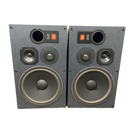
JBL D208H User manual


Contents
Page
Inlroduclion
1
PowerCapacity
2
AmplifierConnection
2
BassLoudspeakers
3
Midrange
And
HighFrequencyDrivers
6
HornsAndAcousticLenses
9
FrequencyDividingNetworks
13
Service
25
JBLcontinuallyengagesinresearchrelatedtoproductimprovementNewmaterials,
productionmethodsanddesign relinements
are
introducedinto existingproductswithout
noticeas
a
routineexpression
ol
thatphilosophy.Forthis
reason,
anycurrent
JBL
product
maydillerinsomerespectfrom
its
publisheddescriptionbutwillalwaysequal
or
exceed
theoriginaldesignspecificationsunlessotherwiseslated.

Excellence
isan
elusivequality
It'sso
easy
to
recognize
yetso
difficult
toattain
JBLcraftsmenhavebeeninvolved
intheartof
sound
(or
morethan
agenerationsignal
and
source,wood
and
fabric,transducers
and
acoustics—all
ofit
Todaythesecraftsmencontinue
to
perform
tothe
mostrigidstandards
anycraftsman
can
submit
to:
thosetheyimposeuponthemselves.
JBLloudspeakers
are
carefullyengineeredinstruments,painstakingly
craftedandassembled
to
watchmakers'standards.
JBL
enclosures
express
the
excitement
of
creativedesign;they
are
elegant,solid
and
flawlesslyfinished.
JBL
transducersandelectronicsofferwhat
has
been
characterizedbydevotedmusiclistenersastheincomparableJBLsound.'
Byfollowing
thefew
simplesuggestionscontained
in
thisbooklet,
you
can
lookforward
to
superbhighfidelityreproductionthatwillretain
itsclarityandrealismyearafteryear.
Introduction
Every
JBL
loudspeakersystem
isthe
product
of
extensivelistening
evaluationcombinedv/ithexhaustiveresearch
and
testing,using
the
most
sophisticatedequipment
and
methodsavailable.
JBL
systemrecommen-
dations
are
based
on
subjectiveevaluation
of
componentperformance
aswell
as
efficiency
and
eleclricalcharacteristicsTheseandothercritical
factorsmust
be
integrated
bya
frequencydividingnetworkengineered
for
the
specificcomponents
ofthe
system
Awell-built,sturdyenclosure
is
essential
for
optimumbassperformance.
Anenclosurehaving
the
properinternalvolume
and
tuning
forthe
loud-
speakerincreases
low
frequencydynamicrangeandimprovestonal
quality:
it
alsoreducesdistortionand
the
possibility
ol
overdriving
the
loudspeaker.
Detailedguidance
on
enclosureconstruction
maybe
obtainedfrom
your
JBL
LoudspeakerComponentsdealer
who
mayalsosupply
the
JBLEnclosureConstruction
Kit.An
illustratedbrochurewith
a
discussion
ofloudspeakertheory
as
woll
as
detailedenclosureconstructiontuning
andfinishinginstructions
for
homeentertainment
and
musicalinstrument
applications
is
contained
inthekit
Actualconstructiondrawings
and
"LoudspeakerComponents
by
JBL'nameplates
for
yourfinished
enclosures
are
alsoincluded.
JBLtransducersareprecisioninstrumentsrespondingwithhighaccuracy
to
the
variations
in
electricalcurrentproduced
by
othercomponents
in
themusicsystemExtraneousnoises,such
as
hum.rumble,crackling
orhissing
donot
originate
inthe
loudspeakers
If
youexperiencedifficulty
realizing
the
fineperformancebuiltintoyour
JBL
components,consult
the
JBL
LoudspeakerComponentsdealerfromwhomtheywere
purchased.
Heis
equippedwith
the
knowledgerequired
to
provideexpert
adviceandassistance.
If.for
somereason,yourJBLdealer
is
unable
to
assistyou,
or
youcannotfind
the
answeryouneedpublished
inJBL
literature,writedirectly
to
theJBLTechnicalServicesDepartmentdescrib-
ing
the
difficulty
in
detail:please
be
certainthatyourreturnaddress
and
telephonenumberareclearlyprinted
on
yourcorrespondence.
1

PowerCapacity
Thespecifiedpowercapacityindicates
the
continuousprogrampower
levelthat
canbe
acceptedwithoutdamage.
The
peakpowercapacity
is
considerablygreaterthan
the
continuousratedvalue,
as
indicated
bythe
remarkabletransientresponse
ofJBL
loudspeakersystemcomponents.
JBLloudspeakerswillreproducecleansound
at
comfortablelistening
levelswhendriven
byan
amplifierhaving
an
output
ofas
little
as10
watts
continuoussinewave
per
channel)However,
for
reproduction
ofthe
full
dynamicrange
of
contemporaryrecordings
at
highvolume,
a
morepower-
ful,
qualityamplifierwillprovideoptimumperformance.Individual,fullrange
orextendedrangeloudspeakers,
or
loudspeakersinstalled
in
systems
rated
upto50
wattscontinuousprogram
maybe
driven
byan
amplifier
delivering
upto75
wattscontinuoussinewave
per
channel;thosehaving
aratedpowercapacity
of50
wattscontinuousprogram
or
greater
maybe
usedwith
an
amplifierdelivering
upto150
wattscontinuoussinewave
per
channel.
Such
an
amplifier
hasthe
reservepowernecessary
for
accurate
reproduction
of
transients,which
can
reachmomentarypeaksequivalent
to
tentimes
the
averagepowerlevel,
inany
case,
an
amplifiershould
be
chosenwith
an
outputpowerralingthatisgreaterthan
the
maximumpower
thatwill
be
used.Thismargin
of
reservepowerwillhelpensurethat
the
amplifierwill
not
attempttodelivermorepowerthanitsdesignallows.When
overdriven,mostamplifierswillclipsignalwaveforms,
a
condition
of
severe
distortionwhich
is
particularlydangerous
to
highfrequencyradiators.
Ifdistortion
is
heard,
oneor
more
ofthe
soundsystemcomponents
is
operatingbeyond
its
capacity(assumingeachcomponent
is
properly
adjusted)
andthe
overallvolumelevel
ofthe
soundsystemshould
be
reduced.
In
almost
all
cases,
the
acousticlevelgenerated
byaJBL
loudspeakerwillbecomenoticeablydiscomforting
totheear
before
the
loudspeaker
can
becomedamaged
by
excessivepowerfrom
the
amplifier.
There
is
virtually
no
danger
of
damaging
a JBL
loudspeaker
ifit
isoperated
within
the
followingguidelines:
I)the
signalfrom
the
amplifier,regardless
of
its
ratedpower,
isnot
distorted;
2)the
amplifier
isnot
drivenintoclipping
(anotherform
of
distortionwhichoccurswhen
the
poweroutputlimitations
of
the
amplifiercircuitry
are
exceeded):
and3)the
powercord
or
audio
connectors
arenot
inserted
or
unpluggedwhile
the
amplifier
is
operating.
However,
a
powerfulwiderangeamplifier
can
accidentallydamage
any
loudspeakerundercertainconditions.
For
example,rewinding
a
tape
recorderwith
the
playbackvolumeturned
upcan
generate"squeals"
powerfulenough
to
burn
outthe
highfrequencyunit.Similarly,powerful
lowfrequencypulsesextendingdowninto
the
subsonicrange
can
eventuallydamage
thelow
frequencyloudspeaker.
Ifthe
phonograph
pickup
is
accidentallydroppedwith
the
volumecontrolfull
up.orifthe
system
is
playedveryloudlywithexcessivebassboost,nearly
the
fullrated
power
ofthe
amplifier
canbe
channeledintodangeroussubsonicenergy.
AmplifierConnection
Important:
Whenconnecting
or
disconnecting
an
extended
or
fullrange
loudspeaker,
ora
completeloudspeakersystemfrom
an
amplifier,
the
amplifiermust
be
turned
off.
Makingconnectionswhile
the
amplifier
is
operatingcouldseriouslydamage
the
loudspeakers
and
void
the
warranty.
1.
The
continuoussinewaverating
of
amplifierpower
isthe
moststringentmethod
currentlyused
inthe
audioindustry.Notethatmanyamplifiermanufacturers
usethe
term"wattsrms"
asa
directequivalent
tothe
moremeaningful"wattscontinuous
sinewave'.'

Forconnections
upto15m (50
ft).
1
mm(#18
AWG)insulatedwire
(ordinaryhouseholdlampcord)
isthe
minimumsizerecommended.
For
longerdistances,werecommend
the
followingminimumsizes:
1.3mm
(#16
AWG)upto30m (100
It),and
1.6mm
(#14AWG)
upto60m (200ft).
Iflampcord
is
used,
wires
canbe
differentiated
by
notingthat
oneofthe
insulatingjackets
is
smooth,while
the
other
hasa
distinctridge.
Locate
the
loudspeakeroutputterminals
onthe
back
ofthe
receiver
or
poweramplifier
For
eachloudspeakersystem,connectthe"black"wire
to
theamplifieroutputterminallabeled"common:'"ground"
or(-),andthe
"red"
wire
tothe
remaining8-ohmspeakeroutput?
The
specified8-ohm
impedanceraling
isa
nominalfigurewhichsuggests
a
connectiongiving
themostefficientpowertranslerbetweenamplifier
and
loudspeakersystem
Notethatmanyamplifiershave
a
chassisgroundingterminalwhich
is
usuallyseparatedfrom
the
otherconnectors.Thisshould
notbe
confused
withthe"ground"designationsometimesused
to
describe
oneofthetwo
terminals
for
eachloudspeakerconnection.
BassLoudspeakers
It
is
goodpractice
to
keep
a
loudspeaker
inits
originalcarton
or
placed
facedown
ona
cleansurfaceuntilinstalled
in
order
to
preventaccidental
conedamage.Thealuminumcenterdome
otan
extendedrangeloud
speaker
is
particularlyfragileandshould
notbe
touched.
A
grille
onthe
front
ofthe
enclosurewillrestrain
the
curiousoncetheloudspeaker
systemiscomplete
Mounting
InAn
Enclosure
Widestsounddistributionwill
be
realized
andresponsethrough
the
midrangeregionwill
be
just
a
littlemorenatural
andtransparentwhen
a
loudspeaker
is
mounted
tothe
front,ratherthan
backsurface
ofthe
bafflepanel.Use
of
T-nutsandmachinescrews,
providedwithin
the
cartonpackingmaterial,allows
the
loudspeaker
tobe
removed
and
reinstalledrepeatedlywithoutdamaging
the
enclosure.
A
second,
larger
seiof
hardware
is
supplied
for
rearmounting
300mm
(12
in)
units.
Thesealbetween
the
loudspeakerframeandbafflepanelmustbeairtight
Whenfrontmounted,a seal
is
achieved
by
fitting
the
whitetubularvinyl
gasketinto
a
groove
onthe
back
ofthe
loudspeakerframe.
(A
flat,
fiber
gasketissuppliedwiththeD208H.)Loudspeakersthat
can
berearmounted
areprovidedwith
a
facinggasket
to
form
a
seal.
An
airtightsealmustalso
bemaintainedwhere
the
inputwiresenter
the
enclosure.
Wheninstalling
the
loudspeaker,tighten
the
mountingscrewsevenly
to
avoid
the
possibility
of
framewarpage.Avoidexcessiveforce;tighten
the
screwsjustenough
to
prevent
air
leaksbetween
the
frame
andthe
enclosure,
2Connectingbothspeakers
as
describedwillinsureproperin-phaseoperation:
i
e..
iheirconeswillrespond
toa
monophonicsignal
by
movingsimultaneously
in
thesamedirection,and
not
oppositetoeachotherInadvertentout-ol-phaseoperation
(whichoccurswhen
onesetot
speakerwires
is
reversedv/ithrespect
to
theother)
will
not
harm
the
system,
but
willcausesomeacousticalcancellationwhichwillhave
theaudibleeffect
ol
reducing
low
Iroquencyresponse.
3

AlthoughJBLloudspeakersareextremelyrugged,theconeand
othermovingpartsaresubjecttoaccidentaldamage.Exercise
extremecautionwheneverusinga screwdriverorothertoolsin
theirimmediatevicinity.
WallMountingTheD208HandLE8T-Hareshallowenoughtomount
betweenthestudsofmostroom
walls.
Werecommendthatyoubecertain
sufficientdepthexistswithinthewallbeforecuttingan
opening.
Whilewall
mountinginevitablycompromiseslowfrequencyperformancetosome
degree,
excellentresuitscanstillbeachievedwhenspaceisnotavailable
fora conventional,portedenclosure.
MountingDimensions
Loudspeaker BattleCutoutDiameter Boll
Circle
Diymoior Frame
MourningHoie
DrillSize
T-Nut
Or ISize
1'
rontMount RearMounl Boll
Circle
Diymoior Frame
MourningHoie
DrillSize FrontMount RearMount
D208H
179
mm
7X,m
179
mm
7Vi.in
194
mm
7% in 5.4mm
in 58 mm
m b8 mm
»1
LE8T-H
t79mm
7M,m
NoiRec-
ommended
194
mm
754in 54 mm
&in 5.8mm
J1
250mm
10-mch
??8mm
H Not
Ree
ommended 245mm
954in 54 mm
(4>in 5.8mm
m
300mm
12-inch 281mm
11Vi«in
281
mm
11
Vi.
in 294mm
11K.in
6
7 mm
•%.in 5.8mm
#1 8mm
5i«in
360mm
14-inch 316mm
9mm NotRec-
ommended 337mm
13VJ
in 6.4mm
5kin 58 mm
Si
300mm
15-inch 355
mm"
13%in 343mm*
t3!4in
3.'Omm*
145i.in
71
mm
Ki
m
5.8mm
'"it! " 8mm
Vie III
•WhenineMA'Sisused.Ihebalt-ecutoutdiametermaybeaslargeasI4V«in;363mm),andinebetìcircle
diameteris
irati
16%in(416mm)toI6J4in(120mm}.T-nutdrills'2e>55<6in(8mm)
UseofTheMA15
TheMA15loudspeakerinstallationkitsimplifiestrontmountingandallowsgreater
latitudeinthediameterofthebafflecutout

InstallingA PassiveRadiatorA
passiveradiator(unclionslike
a
port.
IIcanbeused,wherebattlespacepermits,totuneanenclosuretovery
lowfrequenciesbyvaryingthenumber
of
weightsattached
to
thecone
assembly.A passiveradiatorshouldbeusedonlywiththespecificlow
frequencyloudspeakersforwhich
itis
recommended.
Thepassiveradiatormustbeinstalledwiththeloudspeakerinanairtight
enclosure
of
therecommendedinternalvolume.Mountingdimensions
arethesameasfortheloudspeaker.Foroptimumperformance,placethe
twounitssidebyside;however,theycanbemountedinanyconfiguration
aslongastheyarenocloserthantwoinches(50mm)toeachother,and
notseparatedbymorethansixinches(150mm).Tworemovablemetal
discsareattachedtothecenter
of
thePR15CThefiberboarddiscinfronl
ofthemisintegraltothepassiveradiatorandmustnotberemoved.Each
ofthemetaldiscsweighs100grams.Sixfiberboarddiscsaresupplied
in
thecarton;each
of
theseweighs20grams.
Thepassiveradiatormusthavethepropermassinorder
lo
tunean
enclosuretoIheresonantfrequencyofthelowfrequencyloudspeaker.This
chartprovidesa guidetotheuseofthePR15Cinitsusualapplications.
Tuning
Chart
for
PRI5C
InstallIhonumberofdiscsindicated
tor
the
enclosurevolume
Cm
=
metaldisc
I=
liberboarddisc)
Enclosure
Volume
Ures
GUSC
=081
113
HI
142-
16D
5
1-St)
170-
jjjg •QS-??b
7-
B0
Used
with
LEMH.LE15H 3t 21 11 o-
Used
with
12-11!
136H
1
m
•
• (
1m _ _
•Da
noiristai
mvoJÙW
scre.v
Tuning
A
PassiveRadiator
Whenadding
or
removingluningdiscs,becertainlhatthehardware
is
inihe
sequenceshownTightenIhemachinescrewonlyenough
lo
holdIhediscsand
washerssnuglyinplace.

Fine
TuningAnEnclosure
If
you
are
usingthedetailedplanscontained
intheJBLEnclosureConstructionKit,followtheportinginformation
provided;
it
hasbeenvalidated
bytheJBL
engineering
stafl.
When
constructing
an
enclosure
of
your
own
design,use
of
the
portingchart
for
homeentertainmentloudspeakers(included
in
theJBLEnclosure
Construction
Kit)
willresult
in
excellentbassreproduction.Sinceeach
recommendation
in
the
chart
is
averaged
for
the
range
of
enclosure
volumesindicated,
the
audioperfectionist
may
wish
to
furthertune
his
enclosure
in
order
to
achieveoptimumbasspotential.
The
finetuning
procedureisalsousefulwhendealingwith
an
irregularlyshapedenclosure
forwhichcalculating
the
internalvolumewould
be
difficult.
Thefinetuningprocedure
is
described
in
theJBL
EnclosureConstruc-
tion
Kit.
In
mostinstances,following
the
portingchartwillresult
in
a
measuredtuningfrequencywithin
10%
of
the
optimumrecommended
for
theloudspeaker(seechartbelow),
and
therefore,
the
improvementrealized
bycompletingthefinetuningprocedure
maynot
always
be
audible.
Recommended
TuningFrequency
For
JBL
Loudspeakers
fcncfosure
Model Description tuning
Frequency
124H 300
mm(12
in)lowfrequency
I36H 380
mm(15
in)lowfrequency 26Hz
LESI
H
200
mmf8in]full
range
LE10H 250
mm[10in)
lowfrequency
LE14H 360
mmC14
in)lowfrequency
32Hz
LE15H 380
mm
(15
in)
lowfrequency
32Hz
D130H 380
mm
(15
in)extended
rango 45Hz
130H
380mm
(15
in)
lowfrequency
D208H
200mm
(6in)extendedrange
55
Hz
I)systemtuning
is
hignerthanrecomn-eindcd
forthe
loudspeake'covai
a
portun
pithenon
or
lengthen
ihe
duct
il
oneIs
used.Conversely,
if
systemluniityidkJwarthanrecommendedma«o1r-<jpertterser
or
ahoitanIliaduel.
Whentuning
a
pass-vcradiator.beginwith'e^verwtTflv.ctgntsthanrecommended
for
ttteenclosurevolume
Add
iveights
J
syslsmluning
is
higherIlarirecommendedremrjveweights
it
the
systemtuning.ulortorthandesired
Apassivoradatcrcan
be
lemporantyrrounledinside
PUT
soihc
luningweights
are
easilyaccessibleAdditional
washersused
in
conjunction
winthe
•/.eightssupplied
vvitl
aid
in
obtainingprecisetuning.
Midrange
AndHighFrequencyDrivers
TheLE5H,
LE21H,
075.and
077
mountdirectly
tothe
enclosurebaffle
panel,
andcompressiondriversarebolted
to
theirappropriatehorns.Com-
ponentsandhornsintended
for
enclosuremounting
are
providedwith
a
tubularvinylflangegasket
foran
airtightinstallation.Largefreestanding
horns,
of
course,
donot
requiresuch
a
gasket.
With
the
exception
of
freestandinghorns,
a
highfrequencyunit
is
normallypositioned
onthe
bafflepaneldirectlyabove
or
below
the
bass
loudspeaker,
and
slightly
tothe
side
if
necessary
to
accommodatepanel
dimensions.
If
the
distancebetween
the
pair
of
enclosures
is
limited,
the
highfrequencyunitscan
be
mounted
onthe
outboardside
of
their
respectivebassloudspeakers;conversely,
if
the
enclosures
are
further
apartthanaverage,
the
highfrequencyunitscan
be
mounted
onthe

inboardside
of
Iheirrespectivebassunits.
If
Iheloudspeakersystemis
to
havelow.midrangeandhighfrequencycomponents,placingthemin
a
verticalline(low,midandhigh)willgenerallyprovidewidestandmost
uniformsounddistributionwithinthelisteningroom.Forbestacoustics,
componentsshouldbeasclosetogetheraspractical,butalleast50mm
(2in)aparttomaintainthestructuralintegrity
of
thebafflepanel
Positioningthehighfrequencydrivernear,ordirectingitsoutputtoward,
listenerearlevelwillusuallyresultinthemostrealisticperformance.
Caution:
Topreventseriousdamage,neverconnecta midrange
or
high
frequencytransducerdirectlyloanysourcecapableofgeneratinglow
frequencysignals.Connectionshouldbemadeonlytotherespectivemid
orhighfrequencyterminals
of
therecommendedJBLfrequencydividing
network.
If
separateamplifiersareusedforthevariouscomponents
of
the
system(bi-amplification
or
tri-amplification).
a
properlydesignedhigh-pass
filtermustbeused-inadditiontoanelectronicfrequencydividingnetwork
-toprotectthetransducerfromturn-ontransientsandotheraccidental
lowfrequencysignals.
LE5H
Midrange
Transducer
TheLE5Hmustbehousedinanisolated
sub-chambertopreventinteractionwiththelowfrequencyloudspeaker.
Forsmoothestfrequencyresponsethesub-chambershouldhave
a
minimumvolume
of
1.3litres(80
in3),
andshouldbefilled
lo
moderate
densitywithfiberglassacousticdamping
material.
A sub-chambercan
be
fabricatedof
a
tubehavinganinternaldiameter
of
114mm
(4
ft
in)and
a
length
of
130mm(5in)flushmountedonthebafflepanelandclosedat
itsinteriorend.Inserttheinpulleadsthrough
a
smallholepunched
in
the
side
of
thetube(usecaulkingcompoundtomaintainanairtightseal),and
installthedampingmaterial.Pressthetubularvinylgaskelintothegroove
ontheback
of
themountingflange,connecttheinput
leads,
placetheLE5H
intothetubeandsecure
it
tothebafflepanelwiththefourself-tapping
screwsprovided.
LE21H
HighFrequencyDirectRadiator
TheLE21Hmountsdirectly
to
thefront
of
thebafflepanelusingT-nutsandmachinescrewsThecutout
should
be
105mm[AM in)indiameter,withadditionalclearanceprovided
fortheterminals(seethediagramonthenextpage).Theflatgasketonthe
rear
of
themountingflangewillformanairtight
seal.
PlacetheLE21H
in
themountingcutoutandlightenthescrewsa littleat
a
time,maintaining
evenpressureonthegasket.Donotovertighten,
075And077
The075and077mountfromtherear
of
thebafflepanel
in
an81mm(3?i«in)diametercutout:thedriverisheldinplacebyfour
machinescrewsextendingthroughthebafflepanel.Placethetubularvinyl
gasketaroundthehornandseat
it
againstthemountingbracketprior
to
insertingtheunitintothebafflecutout.NOTE:The077shouldbemounted
withtheslot
vortical,
asshown,toprovidemaximumhorizontaldispersion.
The075producesa conicalsounddistributionpatternandneedsnopar-
ticularmountingorientation
I
105mm
Diameter
075,077MountingDimensions
075Or077Installation
Installthe077asshown,lorwidest
sounddistributioninthehorizontalplane. LE21HMountingDimensions

LEI75.LE85
And376Compression
Drivers
A
compressiondriver
musi
be
bolted
to
theappropriatehighfrequencyhorn,which
in
turn,
will
bemounted
to
thebafflepanel
or
freestanding
ontop
of
theenclosure.
Bolts(%-20.
'Aè'
hexhead)suppliedwiththedrivershould
be
tightened
evenly,
and
justenough
to
achieve
a
snug
fit
withoutovertightening.
The
perforatedcentersection
o(
thefibergasket
onthe
matingsurface
ofthe
drivermust
be
removedbeforeinstallation.
It
is
goodpractice
to
cover
the
exposedthroatopeningwithplasticelectricaltapewheneverthedriver
is
notactuallyinstalled
ona
horn
to
preventforeignmatterfromentering
thedriver,particularlyironfilings
or
chipswhich
canbe
attracted
bythe
strongmagneticfieldwhichexists
in
thedriverthroat
Horns
AndAcousticLenses
Ahorn/lensassemblycouplestheoutput
ofa
compressiondriver
tothe
air
inthe
listeningenvironmentandspreadsthesoundoutwardthroughout
theroom
ina
predeterminedpattern.Thesmallerhorn/lensassemblies
areusuallymounted
to
theenclosurebafflepanel;
the
largerhorn/lens
assemblieswill
be
freestanding
ontop
of
theenclosure.
Caution:
When
a
horn
is
mounted
toa
sturdybafflepanel
of
the
recom-
mendedthickness,
it
will
notbe
necessary
to
supportthedriverHowever,
thedrivermust
be
separatelybraced
or
removedfrom
the
enclosure
whenevertheloudspeakersystem
is
transported,sinceundersuchcircum-
stances
it
is
possible
lor
theweight
of
thedriver
to
pull
the
hornfrom
thebafflepanel.
HL87
Perforated-Plate
Horn/Lens
The
HL87mountsfrom
the
front
of
theenclosure
ina 134mm
(5%?
in)
diameterbafflecutout.
Itis
secured
byfourmachinescrewsandT-nuts.Aftermaking
the
bafflecutout,place
theHL87
in
position
anduse
it
asa
pattern
to
mark
the
location
ofthe
holes
forthe
mountingscrews.Thedrill
bit
sizerequired
for
theT-nuts
is
8
mm(Me
in).
HL88
Perforated-Plate,
HL89
SerpentineAnd
HL90
Slant-Piate
Horn/Lens
Assemblies
Theselargehorn/lensassembliesmount
ontop
of
the
enclosure.Themountingbracketsmust
bo
assembled
tothe
horn/lens
per
theaccompanyingillustrations.TheHL89
is
shownwith
the
MA25installation
kit,
consisting
of
mountingbrackets
anda
bafflewhich
isrequired
for
optimumperformance.
It
is
alsopossible
to
mountanHL89
ontheenclosurebafflepanelusing
the
cutoutillustrated.
HL91,
HL92
And
HL93
Slant-Plate
Horn/Lens
Assemblies
The
HL91.
HL92
and
HL93mount
on
theenclosurebafflepanel,
as
illustrated-
The
bafflecutout
is108mm
(4%
in)in
diameter.Countersink
the
four
7 mm
0&
in)
holes
forthe
flatheadmountingscrews
The
whitevinylringgasket
should
be
placed
onthe
hornmountingflange
to
insureanairtight
seal.
(Continued
on
page
12.)

10


MountingThe
HL91,
92And93
Thelensisaffixedtothefrontsurfaceofthepanelwithhook-and-pile
mounting
tape.
Whilethe"pile"stripsarestillattachedtothe"hook"
sectionsonthelens,removethepaperbackingtoexposetheadhesive,
placethelensinpositionoverthebaftlecutout,andpresstheadhesive
againstthepanel.Removethelensfromthetape(itnecessary,remove
thetapeas
well,
altermarkingitslocationonthebaffle)andpermanently
affixthetapetotheenclosurewithstaplesorsmallcarpettacks.Asthe
lensisremovedfromthetape,a "ripping"soundwillbeheard,indicating
normaldisengagement.
Aclearanceof67mm[2%in)betweenthebafflepanelandthegrille
assemblyisrequiredforthe
lens.
Thegrilleshouldwraparoundtheenclo-
suresothatbothsidesaswellasthefrontofthelensareunobstructed,
foroptimumsounddistribution.Ifthesidesoftheenclosuremustbecom-
pletely
solid,
a wedgebuiltupoffiberglassshouldbecementedinposition
oneithersideofthelens,runningthefullheightoftheenclosure.Ledges
atthetoporbottomofthebafflepanelshouldbetreatedin
a
similarmanner.
TopViewOfLensInstallation
12

254mm
10in
184rr.m
VA
m
HL91,
HL92
And
HL93MountingDimensions
FrequencyDividingNetworks
JBLdividingnetworksprovideimperceptibledistribution
of
theaudiosignal
among
the
transducers
ofthe
loudspeakersystem.
AllJBL
networks
are
engineered
to
match
the
exactcharacteristics
of
specificcomponents,
including
the
horn/lensassembly,
as
shown
inthe
NetworkSelection
Chart.We
donot
recommendusing
JBL
loudspeakersystemcomponents
inothercombinations
or
withthose
of
othermanufacturers.
Adjustment
Each
JBL
dividingnetwork
is
providedwith
a
levelcontrol
thatpermitsmatchingloudspeakersystemperformance
tothe
acoustic
characteristics
ofthe
listeningroom
andto
listenerpreference.
The
control
regulates
Ihe
amount
of
power
fed tothe
highfrequencytransducer.
It
does
not
affect
the
crossoverfrequency,
nor
does
it
limit
the
upper
frequencyresponse
of
theloudspeakersystem.
Adjustment
of
thelevelcontrolshould
be
madeonthebasis
of
evaluation
ofnormalprogrammaterialplayedmonaurallywithamplifiertonecontrols
at
the
middle,generallyreferred
toas
"flat!'position.Once
the
loudspeaker
system
has
beenbalanced
for
bestoverallresults,compensation
for
additionaldifferences
in
programmaterialshould
be
madewith
the
tone
controls
onthe
preamplifier
or
receiver.
Genera'—Generalapplicationnetworkshaveeither
a
continuouslyvariable
orthreepositioncontrol.With
the
control
inthemid
position,evaluate
the
relativeloudness
of
highfrequencyprogrammaterial
and
raise
or
lower
thecontrolsetting
to
obtain
the
mostrealisticmusicalbalance.When
two
dividingnetworks
are
required,suchasanN8000usedinconjunctionwith
anLX13.first
setthe
highfrequencynetworkcontrol
atits
minimum
position(sothe
ear
willperceiveonly
the
balancebetween
thelow
frequencyandmidrangecomponents),secondly,adjust
thelow
frequency
network
for
themostpleasingbalance,andfinally,adjustthehighfrequency
network
forthe
mostpleasingtrebleperformance.
13

LX30
and
LX300-Vne
LX30andLX300havePresence(midrange)and
Brilliance(highfrequency)controls.RotatetheBrilliancecontroltothe
minimum
position,
adjustthePresence
control,
andthensettheBrilliance
control.
Mounting
Generalapplicationdividingnetworksareusuallymountedon
therearpaneloftheenclosure.Thecutoutpatternillustratedislorself-
containednetworksandforthecontrolassemblyofthelargerLX30.LX50A
andLX80A.Woodscrews,aswellasmachinescrewsandT-nuls,arepro-
videdtosecuretheassemblytotheenclosure.Becertainthatthewhite
vinylflangegasketisinplaceinordertomaintainanairtight
seal.
Themain
assemblyofthelargernetworksisnormallyplacedononeoftheinterior
surfacesoftheenclosureandsecuredbyfourmachinescrewsextending
throughthepanelintothreadedfastenersonthenetwork.
LX30.
LX50AandLX80A
203mm
8n
U3rr.m
554in
Himm
4Sin Gin
LX300
6'/.in
111
mrn_
NetworkMountingDimensions

NetworkConnection
Thenetworkinputterminalsshouldbeconnected
totheamplifierloudspeakeroutputs.Connecttheblackterminalotgeneral
applicationnetworkstothenegativeamplifieroutput,andtheredterminal
tothepositiveamplifieroutputHeavy-dutynetworksareprovidedwith
screwterminalsTheinputterminallocatedonthewhiteline,marked"C"
lorcommon,shouldbeconnectedtothenegativeamplifieroutput;
connecttheotherinputterminaltothepositiveamplifieroutput.
Generalapplicationnetworkshaveeyeletsthaiallowleadwirestopass
throughtheflangeintotheenclosureandatthesametimemaintainan
airtight
seal.
TheLX30,however,hasscrewterminalsonthebackofthe
controlassembly.Color-codedwiresareprovided,althoughany18-gauge
insulatedwirecanbesubstituted.Theproperwiregaugefortheamplilier
connectionisdiscussedunderAmplifierConnection
Connectionsbetweenthenetworkandthecomponentsareillustrated
intheaccompanyingdiagrams,asindicatedintheNetworkSelection
ChartCareshouldbetakentofollowthediagramsexactlytoensurethat
componentswilloperalointheproperphaserelationshipwitheachother.
Notethathighfrequencycompressiondriverphasingisa function
of
the
crossoverfrequencyaswellasthehorn/lensassembly
utilized.
Thewiring
illustrationsarecorrectwhenanHI.87.HL91.HL92
or
HL93ismountedon
theenclosurebafflepanel,andwhenanHL88.HL89orI1L90ispositioned
sothatthehornmouthisflush(even]withtheenclosurebafflepanel.
If
the
horn/lensassemblyismovedmorethansixinchestoward
or
awayfrom
thelistener(withrespecttothemountingconditionsjustoutlined),install
a
phasereversingswitchfdoscribedonpage24) andauditionmalevocal
materialwhilechangingphaseofthehighfrequencydriver.Utilizethephase
conditionwhichyieldsthemostnaturalreproduction.
Network
Selection
Chart
Network
Low
frequency
Transducers
Midand
High
Frequency Horn/t
ons
Assembly
Illus-
tration
LX5
LEI5H
376'
HL93
A
0
LXIO LE14H LE175.LE85 IIL87
HL9I D
LXI3 LE15H LE175,LE85 HL92
A
1X14
LEIOH LFPIH
C
LX30 124H.LEI4H
LE5H+077
I
LX50A
130H,
I36H
376'
HL88HL89.HL90
F
LX80A
124H.130H.136H
LE14H LE175.LE8S.376
HL92.
HL93
F.G
1X200R
I24H.
!36H.Lbl4H IE175.LE85
IIL91
K
LX300
124H.136H.LEI4H
LE
175+077
LE85+
077
HL9?
L
N1200
DI30H.
I30H LE175.LE85
HL87.HL91
H
N2400 Q130H
075 1
N7000 376+075
376+077
J
N8000 LE175+
075
LE175+Q77
LE85+075
LE85
'077
J
'S'vaiine
a/6sapi!i-ar90CC''"pftt*^oofl''VC*"-8P
M7000
wft
anO/Sof
077
*r.J
im
wquirM
?ar
extended
*vg*
'roarer*:/
rep'od.xi
on
•Whirl
tre
376
is
JSSO
«*nt*e
LXWA
connectThe
N'OCO
ai
-f
i
«ere
<N»
compfett'en
flavor
shown
m
lustrate
f
Cc^ecW-s
W«l
meN7CC0
to
re
376
and
075
cr
377
g-e
snown
i
kn
fate"
J
15

A
System
Wiring
Illustrations
NoieThecolorcodesillustratedrepresentthelatestconfiguration.Earlierunitswere
suppliedwithIwoblackwiresinsteadotgreen/blackandyellow/blackwires,anda
redwireinsteadofIheyollowwireshown.

c
NoieThecolorcodesillustratedrepresentthelatestconfigurationEarlierunitswere
suppliedwithtwoblackwiresinsteadolgreen/blackandyeilow/Wackwires,anda
redwireinsteadolIneyellowwireshown.

18
Noto:
Thecolorcodesillustratedrepresentthelatestconfiguration.Earlierunitswore
suppliedwithtwoblackwiresinsteadotgreen/blackandyellow/blackwires,anda
redwireinsteadoftheyellowwireshown.
This manual suits for next models
8
Table of contents
Other JBL Speakers manuals

JBL
JBL Control Control 226CT User manual

JBL
JBL SVA CENTER User manual

JBL
JBL Pulse2 User manual

JBL
JBL Cabaret Series User manual

JBL
JBL L222 User manual

JBL
JBL Control Control 25T User manual

JBL
JBL INSTALLATION P81BB User manual

JBL
JBL NO TOUR IBT User manual

JBL
JBL VP7215 Specification sheet

JBL
JBL PRX718XLF User manual