Rave RK-650-ICA-B User manual

Owner’s Manual
RK-650-ICA-B/RK-830-ICA-B/RK-650-IC-B/
RK-650-SIS-IC-B/RK-800-IC-B
RK Series
In-Ceiling Speaker
Rave Technology
G6434 South Dort Highway, Suite 2
Grand Blanc, Michigan 48439
Tel: 1-810-953-3918
www.ravetechnology.com

Introduction
Thank you for your purchase and welcome to the growing community of
satisfied Rave Technology listeners. Please read the following installation
and operation guidelines carefully to ensure enjoyment of your custom
installed home audio system, for years to come. All
speakers should be set-up and installed by authorized and duly
licensed technicians.
Your custom installation speakers are designed to blend
seamlessly into your home interior while providing superior sound quality.
At , we continuously strive to improve our products.
For this reason, we reserve the right to change product specifications without
notice. The information concerning product specifications and instructions in
this manual do not necessarily set forth all technical or other specifications of
Products.
Rave Technology
Rave Technology
Rave Technology
Rave Technology
For more information about our company and our products, please
visit our website at www. .com.ravetechnology
Rave Technology
Rave Technology
G6434 South Dort Highway, Suite 2
Grand Blanc, Michigan 48439
Tel: 1-810-953-3918
www.ravetechnology.com

Features and Benefits
Your custom installation speakers are designed to blend
seamlessly into your home interior while providing superior sound quality.
All custom installed products feature a self-engaging
mounting system that does not require brackets. Simply cut a hole in the
mounting surface, remove the grille from the speaker, connect the wires and
place the speaker in the hole. Then tighten the four or six mounting “dogs”
using the front panel screws. The dogs will automatically rotate 90 degrees
then clamp the speaker frame to the mounting surface as you tighten the
screws.
offers pre-construction brackets with all its custom
installed speakers. The pre-construction brackets can be installed where the
speakers will be mounted before the drywall goes up. The drywall contractor
will cut the corresponding holes as the drywall is installed. This reduces the
installation time and allows for pre-planned wiring.
All speaker or pair of speakers includes a Cut-out template and Paint mask.
The Cut-out template allows the installer to accurately measure the hole to
be cut in the dry wall. The Paint mask provides protection for the woofer and
tweeter while painting the speaker baffle.
The two-piece baffle design allows the tweeter to be directly mounted on the
bridge itself rather than the pole mounting found in most current designs. This
setup allows the speaker to handle more power with increased cone stability,
resulting in decreased harmonic distortion.
Rave Technology
Rave Technology
Rave Technology
Installation
Pre-Construction Bracket
Cut-Out Template and Paint Mask
Stable Tweeter Housing
Do not over tighten.
Rave Technology
G6434 South Dort Highway, Suite 2
Grand Blanc, Michigan 48439
Tel: 1-810-953-3918
www.ravetechnology.com

Important Safety Instructions
Do not
Clean only
Do not
Do not
Use
Refer all servicing
No user-serviceable parts inside.
Warning:
Warning:
Caution:
use this or other electrical equipment near water or other liquids.
with dry cloth.
block any ventilation openings. Install in accordance with all safety
standards and regulations.
install near any heat sources such as stoves, radiators, heat
registers, amplifiers or any other apparatus producing heat.
attachments and accessories as indicated by the manufacturer.
to qualified service personnel. Servicing is required
when the apparatus has been damaged in any way, liquid has been
spilled or objects have fallen into the apparatus, the apparatus has been
exposed to rain or moisture, does not operate normally, or has been
dropped.
Refer all servicing to qualified service
personnel.
To reduce the risk of fire or electrical shock, do not expose this
apparatus to rain, other liquids or moisture.
To prevent injury, this apparatus must be securely attached to
the wall/ceiling in accordance with the installation instructions. No naked
flame sources such as candles should be placed close to the product.
Changes or modifications not expressly approved by the
manufacturer could void the user's warranty to operate this device.
Installation
Rave Technology
G6434 South Dort Highway, Suite 2
Grand Blanc, Michigan 48439
Tel: 1-810-953-3918
www.ravetechnology.com

RK Series Speaker Installation Guide
At , we continuously strive to improve our products. For this
reason, we reserve the right to change product specifications without notice.
The information concerning product specifications and instructions in this
manual do not necessarily set forth all technical or other specifications of
products. Additional information can be obtained on-line at
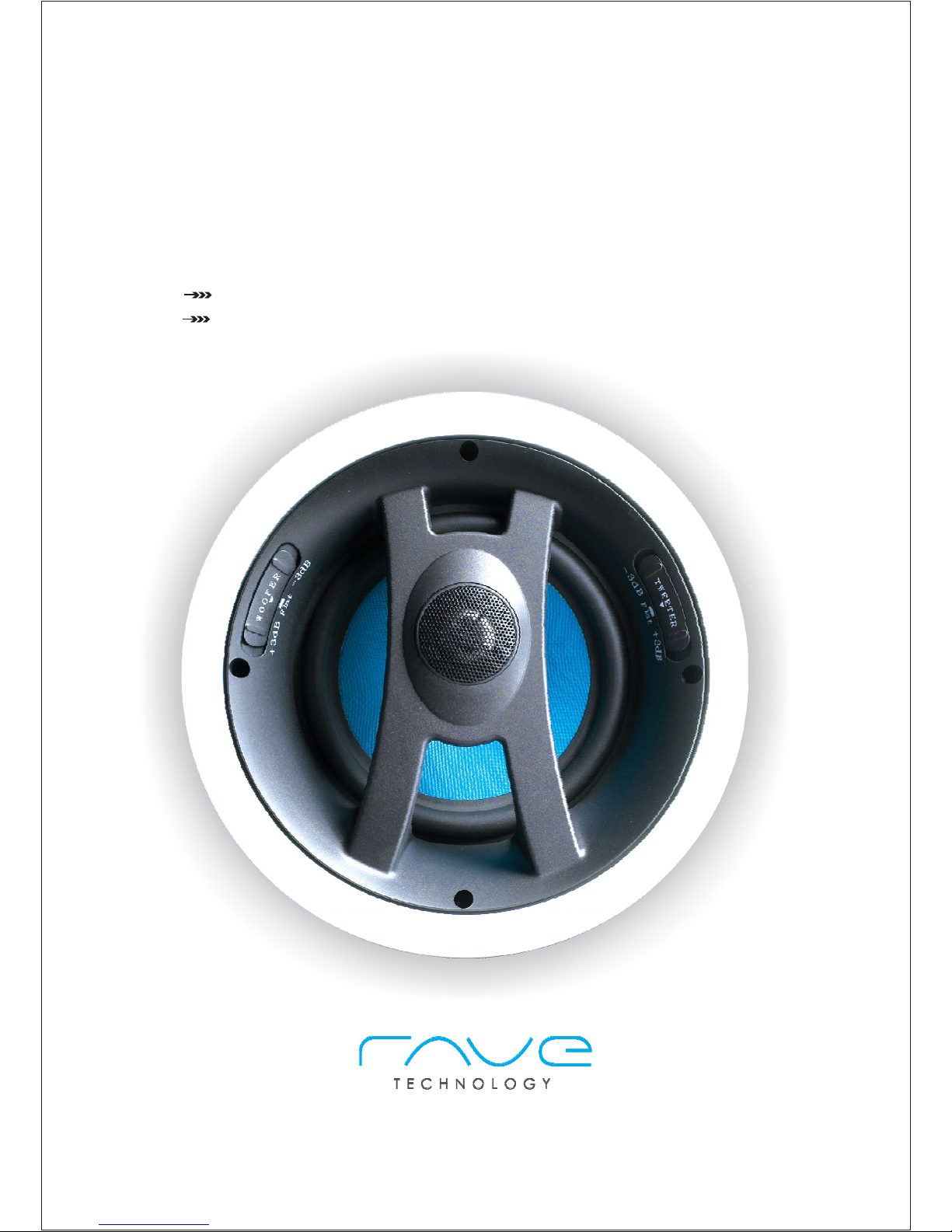
With , realizing maximum sound performance is always
the goal. The pivoting tweeters in speakers are able to
compensate for unusual placements. However, placing speakers at equal
distance from the intended listening area and along a common wall is
generally recommended as the ideal acoustical set-up. This helps to
ensure the best stereo effect. Where the intended listening position may
vary widely, speaker placement may be wherever is most convenient.
custom install speakers are designed to function in
any standard wall, ceiling or drop ceiling.
speakers possess extremely smooth and predictable
off-axis frequency response. The chart below shows how far apart the
speakers can be placed in a distributed audio system. The calculations are
based on+/- 45 degrees of coverage from the speaker, and listener ear
heights of 62'' for standing and 40'' for seated listener.
Rave Technology
Rave Technology
Rave Technology
Rave Technology
Rave Technology
Rave Technology
www. .comravetechnology
LS Series Speaker Placement
DISTRIBUTED AUDIO PLACEMENT
Listening/Viewing Area
Center
Right FrontLeft Front
Left Rear Right Rear
Subwoofer
Listening Area
Fig.1 Stereo Sound Layout
Right ChannelLeft Channel
To ensure the best stereo effect,place speakers
along a common wall at equal distances from
the intended listening area.
Fig.2 Home Theater Layout
The same principle applies for surround effect
in a Home Theater System. A
Subwoofer completes the 5.1 Home Theater
sound.
Rave Technology
Speakers spacing Standing Listener Seated Listener
8 foot ceiling
10 foot ceiling
12 foot ceiling
14 foot ceiling
5.7'
9.7'
13.7'
17.7'
9.5’
13.5’
17.5’
21.5’
2 CHANNEL AUDIO PLACEMENT
HOME THEATER PLACEMENT
In a standard two channel audio system, the speakers should be separated
approximately6-10feet apart. If possible, the left and right speakers should
be located at the same distance from the listening position.
When using the speakers as a rear channel speaker, the speakers should be
located from 2 to 6 feet behind the main listening position. The speakers
should be separated approximately 6 to 10 feet apart.
TV
Rave Technology
G6434 South Dort Highway, Suite 2
Grand Blanc, Michigan 48439
Tel: 1-810-953-3918
www.ravetechnology.com

Drywall Installations
Contents Description Quantity
Tools Required
Pre-Construction Brackets
1.
2.
Drywall or other mounting surfaces should be at least 3/8" thick to ensure safety and
speaker stability. Speaker placement should be planned to accommodate practical
considerations such as wiring path and installation surfaces. Your professional installer
will be able to advise you of the best layout.
- Speaker Modules -2 (SIS Models -1) - Grilles -2 (SIS Models -1)
- Paint Mask-1
- Cut-out Template -1
#2 Phillips Screwdriver
Hole Saw
Pre-construction brackets are available with all Rave Technology custom installed
speakers. These brackets are measured to fit standard 16''/24'' wood stud intervals.
Nail or Staple the pre-construction brackets to the stud in the planned speaker position.
With the flange of the speaker cut out facing out.
As the drywall installer is working, they can accurately cut-out the necessary hole for
your speaker reducing installation time and debris when the speakers are being installed.
New Construction
Wood stud
Nail into position
Pre-construction bracket
WIRE GAUGE AND QUALITY
The total wire resistance should be less than 10% of the speaker impedance. If using an
8 ohm speaker, your total wire resistance should be no more than 0.8 ohms.
In simple terms, the extra resistance from the wire will have a very negative effect on the
sound quality of the speaker. The sound can be less dynamic, definition of bass
frequencies can be reduced, an in extreme cases, the high frequencies can be attenuated.
Amplifier power is also wasted in the wire, reducing the maximum output level of the system.
Please refer to the following chart when deciding on the appropriate wire gauge for your
installations.
Distance in Feet
20 g ugea
18 g ugea
16 g ugea
14 g ugea
12 g ugea
10 g ugea
50’ 100’ 150’ 200’ 250’ 300’
Wire resistance in ohms vs. Length of cable run
.86 1.73 2.59 3.45 4.32 5.18
.65 1.30 1.94
2.59
3.24
3.89
.43 .85 1.28 1.71 2.14 2.56
.27 .54 .81 1.08 1.35 1.62
.17
.34
.51 .68 .85 1.02
.11
.22
.33 .44 .56 .67
Rave Technology
G6434 South Dort Highway, Suite 2
Grand Blanc, Michigan 48439
Tel: 1-810-953-3918
www.ravetechnology.com

PAINTING THE SPEAKERS AND GRILLES
Speaker baffle and grilles can be painted before installation, which will
eliminate the “paint scar” if the speaker needs to be removed for service.
Speakers may also be painted after installation, but before the grilles are
attached. All speakers come from the factory with paint mask included.
Use the paint mask to protect the drivers while the baffle is being painted
with the ceiling.
Rave Technology suggests always painting the grills separate from
the speaker. The grilles may be lightly sprayed with thin paint (5 parts
thinning agent to 1 part paint), but be careful not to plug the holes. Too
much paint will adversely affect the sound of the speaker.
Once the grilles and baffle are painted and dry, remove the paint mask
from the baffle and install the grilles.
Rave Technology in-ceiling frames and grilles are designed to accept
most types of paint. Care should be taken to avoid excessive paint
build-up in the grille perforations.
Once the hole is cut, clean all edges and debris from the area. Attach
the wire from your amplifier to the terminals on the back of the speaker.
Double check the polarity of the speaker wires, amplifier + to speaker
+ and amplifier - to speaker - proper polarity is critical in home theater
installation.
Insert the frame into the wall opening and attach to the mounting
surface by tightening the screws to engage the swinging “dog” connectors.
The frame's mounting dogs will “sandwich” the wall and frame together.
Install the module and press the grille in place. Start the insertion of the
grill on one edge and slowly work your fingers around the grille edges.
Make sure all edges are in the groove before you apply pressure. Do not
push hard. If the grille is not going in, this means not all edges are in the
groove. Ease off grille and start over.
3.
4.
5.
Rave Technology In-ceiling
speakers feature swiveling tweeters
to aim sound directly at the listening
area, simply remove the grille and
gently adjust the tweeter to the
desired position.
Rave Technology
G6434 South Dort Highway, Suite 2
Grand Blanc, Michigan 48439
Tel: 1-810-953-3918
www.ravetechnology.com

Existing Construction
1.
2.
3.
4.
Cut the appropriate size opening in the wall using the cutout template
provided. Be careful not to cut through any existing wiring or plumbing.
Note: Avoid compromising any fire stops between studs.
Run wiring to the wall opening(s). Be sure to comply with any codes that
may apply in your area.
Attach the wire from your amplifier to the terminals on the back of the
speaker. Double check the polarity of the speaker wires, amplifier + to
speaker + and amplifier - to speaker - proper polarity is critical in home
theater installation.
Insert the frame into the ceiling opening and attach to the mounting surface
by tightening the screws to engage the swinging “dog” connectors.
. The frame's mounting dogs will “sandwich” the wall and
frame together. The module is installed with the screws and the grille is
pressed into place.
PAINTING THE SPEAKERS AND GRILLES
Speaker baffle and grilles can be painted before installation, which will eliminate
the “paint scar” if the speaker needs to be removed for service. Speakers
may also be painted after installation, but before the grilles are attached. All
speakers come from the factory with paint mask included. Use the paint
mask to protect the drivers while the flange is being painted with the ceiling.
Rave Technology suggests always painting the grills separate from
the speaker. The grilles may be lightly sprayed with thin paint (5 parts
thinning agent to 1 part paint), but be careful not to plug the holes. Too
much paint will adversely affect the sound of the speaker.
Once the grilles and baffle are painted and dry, remove the paint mask
from the baffle and install the grilles.
Install the module and press the grille in place. Start the insertion of the
grill on one edge and slowly work your fingers around the grille edges.
Make sure all edges are in the groove before you apply pressure. Do not
push hard. If the grille is not going in, this means not all edges are in the
groove. Ease off grille and start over
Do not
over tighten
5.
When using the supplied cutout
template, take care not to cut through
any existing wiring or plumbing.
Cutout for speaker
Wood stud
Rave Technology
G6434 South Dort Highway, Suite 2
Grand Blanc, Michigan 48439
Tel: 1-810-953-3918
www.ravetechnology.com

SIS SERIES- The 650- SIS series use the same installation directions as all
speakers. Please pay close attention to the wiring of the speakers. The SIS-Series produces the
left and right audio signal from one speaker. The crossover on the back of the speaker, shown
below, features two pairs of push-to-connect gold terminals.
Rave Technology
Attach the wire from your amplifier to the terminals on the back of the speaker. Double check the
polarity of the speaker wires, amplifier + to speaker + and amplifier - to speaker -
. The left and right channels are the same regardless of which side you connect the speaker
wires
– features baffle mounted level control for bass, midrange and
treble frequencies. The level controls will help you to fine tune the performance of the crossover to
meet any demanding room issues or listener preferences. The level controls each adjust an octave
wide band of frequencies most affected by the interaction between the drivers. The controls can be
adjusted to provide 3dB of boost or 3dB cut on each of the drivers in any RK- Series speaker. The
level controls are able to help you maximize sound quality regardless of room setup and speaker
placement.
Note: Do not apply pressure to the tweeter dome.
The pivoting tweeter can direct sound toward or away from the listening area. To pivot the tweeter,
apply light pressure to the plastic ring around the outside edge of the tweeter
Here are some suggestions:
Orient the pivoting tweeter toward the listening area if the speakers are widely separated and the
music fails to blend into a central image when the system is operated in stereo.
If you are using the speakers as channels in a home theater you can point the pivoting tweeter
towards a wall or window to create a diffuse surround affect.
If you have any questions about how the pivoting tweeter should be adjusted, consult your authorized
dealer.
proper polarity is
critical
SETTING THE TONE CONTROL
RK series
ADJUSTING YOUR SPEAKERS
Rave Technology
Rave Technology
Rave Technology in-ceiling frames and grilles are designed to accept most types of paint. Care
should be taken to avoid excessive paint build-up in the grille perforations.
If you want to paint the decorative frame and the ceiling together, insert the frame and attach with the
dogs.
If you will not be re-painting, you may immediately install the frame and speaker assembly. The
frame's mounting dogs will “sandwich” the wall and frame together. The module is installed with the
screws and the grille is pressed into place.
6.
7.
Red +
Black - + Red
- Black
terminal post
terminal post
Rave Technology
G6434 South Dort Highway, Suite 2
Grand Blanc, Michigan 48439
Tel: 1-810-953-3918
www.ravetechnology.com

RK Series
Specifications
RK Series In-Ceiling Speaker Specifications
RK-650-ICA-B
6.5” Angle In-Ceiling Speaker
R - -IC
” In-Ceiling Speaker
K 830 A-B
8 3- Way Angle
Rave Technology
G6434 South Dort Highway, Suite 2
Grand Blanc, Michigan 48439
Tel: 1-810-953-3918
www.ravetechnology.com
6.5” Woven Kevlar cone, rubber surround, 22oz Magnet, 1" voice coil, Bumped back plate,
vented pole piece
1" Titanium Dome tweeter, Ferro-fluid cooled, Neodymium magnet, Swivel 30 degrees
FR4 PCB board, 12dB woofer section,
12dB tweeter section, Polyimide auto protective reset switchfor tweeter
16AWG wire connection to woofer section
Gold plated terminal posts will accept 14AWG wire
+/- 3dB On woofer and tweeter
48Hz- 22KHz
88dB
10-150 watts
4 / 8ohm switchable on PCB
7.95"
11LBS
15.5” (H) 11.5” (W) 11" (L)
SHIPPED WITH GRILLES,
PAINTMASK, CUTOUT TEMPLATES AND
PRE-CONSTRUCTION BRACKETS
Woofer:
Tweeter:
Crossover:
Attenuation switches:
Frequency Response:
Sensitivity:
Recommended amplifier power:
Impedance:
Cut Out size:
Weight (pair pack):
Dimensions (pair pack):
Woofer:
Midrange:
Tweeter:
Crossover:
Attenuation switches:
Frequency Response:
Sensitivity:
Recommended amplifier Power:
Impedance:
Cut Out size:
Weight (pair pack):
Dimensions (pair pack):
8” Woven Kevlar cone, rubber surround, 25 oz Magnet, 1.25" voice coil, Bumped back plate,
vented pole piece
3" Woven Kevlar cone, rubber surround,
1" Titanium Dome tweeter, Ferro-fluid cooled, Neodymium magnet. Swivel 30 degrees
FR4 PCB board, 6dB Woofer section, 24dBmidrange section, 12dB tweeter section, separate
polyimideauto protective reset switch for tweeter and midrange
16AWG wire connection to woofer section
Gold plated terminal posts will accept 14AWG wire
+/- 3dB On woofer, tweeter and midrange
45Hz- 22KHz
89dB
10-150 watts
4 / 8 ohm switchable on PCB
9.64"
15.75LBS
17.75” (H) 13”(W) 13.75” (L)
SHIPPED WITH GRILLES,
PAINTMASK, CUTOUT TEMPLATES AND
PRE-CONSTRUCTION BRACKETS

R - -IC
” In-Ceiling Speaker
K 650 -B
6.5
RK-800-IC-B
8” In-Ceiling Speaker
Rave Technology
G6434 South Dort Highway, Suite 2
Grand Blanc, Michigan 48439
Tel: 1-810-953-3918
www.ravetechnology.com
Woofer:
Tweeter:
Crossover:
Attenuation switches:
Frequency Response:
Sensitivity:
Recommended amplifier power:
Impedance:
Cut Out size:
Weight (pair pack):
Dimensions (pair pack):
6.5” Woven Kevlar cone, rubber surround, 22oz Magnet, 1" voice coil, Bumped back plate,
vented pole piece
1" Titanium Dome tweeter, Ferro-fluid cooled, Neodymium magnet, Swivel 30 degrees
Phonalic PCB board, 12dB woofer section,
12dB tweeter section, Polyimide auto protective reset switch for tweeter
16AWG wire connection to woofer section
Gold plated terminal posts will accept 14AWG wire
+/- 3dB On woofer and tweeter
48Hz- 22KHz
88dB
10-150 watts
4 / 8ohm switchable on PCB
7.95"
11LBS
15.5” (H) 11.5” (W) 11" (L)
SHIPPED WITH GRILLES,
PAINTMASK, CUTOUT TEMPLATES AND
PRE-CONSTRUCTION BRACKETS
Woofer:
Tweeter:
Crossover:
Attenuation switches:
Frequency Response:
Sensitivity:
Recommended amplifier power:
Impedance:
Cut out size:
Weight (pair pack):
Dimensions (pair pack):
8” Woven Kevlar cone, rubber surround, 25 oz Magnet, 1.25" voice coil, Bumped back plate,
vented pole piece
1" Titanium Dome tweeter, Ferro-fluid cooled, Neodymium magnet, Swivel 30 degrees
Phonalic PCB board, 12dB Woofer section, 12dB tweeter section,
polyimide auto protective reset switch for tweeter
16AWG wire connection to woofer section
Gold plated terminal posts will accept 14AWG wire
+/- 3dB On woofer and tweeter
45Hz- 22KHz
89dB
10-150 watts
4 / 8ohm Switchable on PCB
9.64"
15.75 LBS
17.75” (H) 13”(W) 13.75” (L)
SHIPPED WITH GRILLES,
PAINTMASK, CUTOUT TEMPLATES AND
PRE-CONSTRUCTION BRACKETS

R -650-SIS
6.5” In-Ceiling Stereo Speaker
K -IC-B
R SERIESK -SIS
Rave Technology
G6434 South Dort Highway, Suite 2
Grand Blanc, Michigan 48439
Tel: 1-810-953-3918
www.ravetechnology.com
Woofer:
Tweeter :
X-over :
Frequency response :
Sensitivity :
Recommended amplifier power :
Impedance :
Cutout size :
Weight (single pack) :
Carton dimensions (single pack):
6.5”, dual 1" voice coil, woven kevlar cone, 22 oz magnet, bumped back plate, vented pole piece
dual 19mm titanium dome, ferro-fluid cooled, 30 degree swivel and pivot, neodymium magnet,
Phonalic PCB board with18dB per octave crossover for tweeters and woofer sections
Polyimide switch-auto protect reset switch, over power protection for both tweeters
16AWG wire connection to woofer section
Gold plated terminal posts will accept 14AWG wire
45Hz-22kHz
88dB 1W/1M
10-100 watts per channel
8ohm per channel
7.95"
6.5 lbs
8"(H) X 11"(W)X 11"(L)
SHIPPED WITH GRILLE,
PAINTMASK, CUTOUT TEMPLATES AND
PRE-CONSTRUCTION BRACKETS

Warranty
Limited Life Time Warranty:
1. Damage caused by courier shipping, accident, abuse, improper installation, improper operation,
water and theft.
2. Any cost or expense related to removal or reinstallation of the defective product.
3. Service performed by anyone other than an Authorized Rave Technology service depot.
4. Any product purchased from an unauthorized dealer, proof of purchase from an Authorized
dealer is a MUST.
Rave Technology offers a Limited Lifetime Warranty on most Speaker products sold
by Authorized Dealers. Product found to be defective will be repaired or replaced with
equivalent product.
Warranty Exclusions:
Zip:
Name:
Street Address:
City/State:
Home Phone:
Work Phone:
E-mail Address:
Model and Serial Number:
Store Name: State:
Purchased from:

stamp
Rave Technology
G6434 South Dort Highway, Suite 2
Grand Blanc, Michigan 48439
Tel: 1-810-953-3918
www.ravetechnology.com
Rave Technology
This manual suits for next models
4
Table of contents
Other Rave Speakers manuals
Popular Speakers manuals by other brands

Sony
Sony SS-X30ED Marketing Product information

Bose
Bose Sub1 quick start guide

Arctic
Arctic Sound S361 datasheet

AUSTRALIAN MONITOR
AUSTRALIAN MONITOR XDS8 Installation and operation manual

Definitive Technology
Definitive Technology Mythos SoloXL owner's manual

Pure Acoustics
Pure Acoustics Proxima 60 Specifications