8
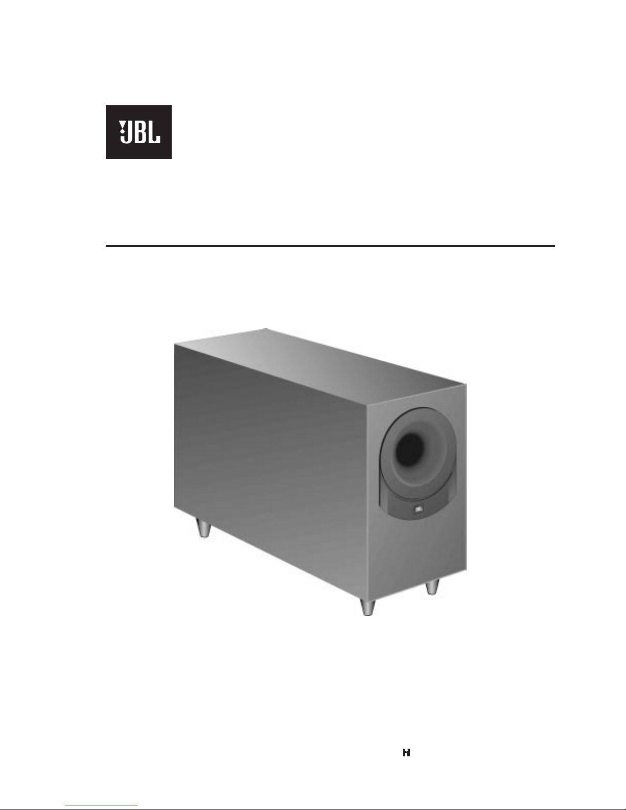
Powered Subwoofer BASS20
MECHANICAL PARTS LIST
REF. NO. PART NO. DESCRIPTION QTY
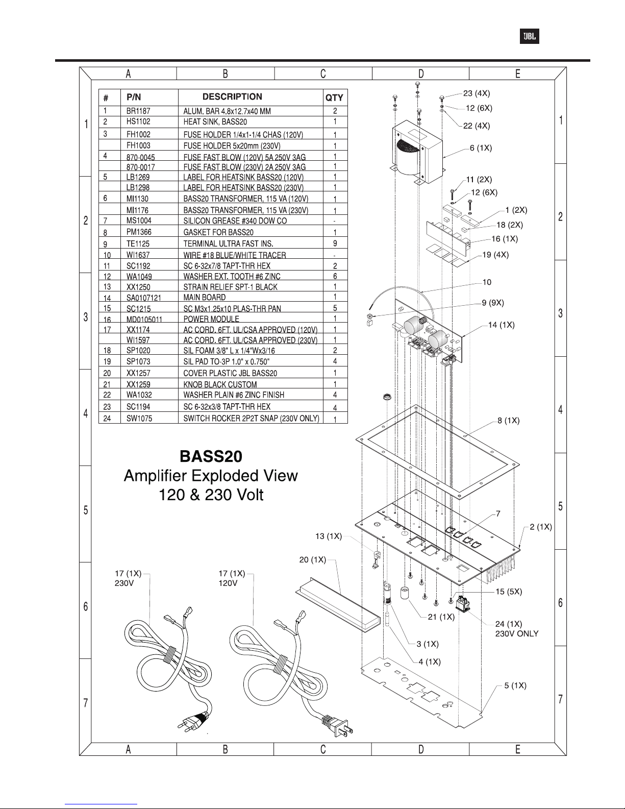
1 BR1187 ALUM. BAR 4.8mmx12.7mmx40m 2
BR1387 ALUMINUM BAR 1.9"x0.5"x0.1 1
2 HS1102 HEAT SINK ASSY. 1
3 FH1002 FUSE HOLDER 1/4x1-1/4 (120V) 1
FH1003 FUSE HOLDER 5x20mm (230V) 1
4 SEE FUSES
5 LB1269 LABEL FOR HEATSINK (120V) 1
LB1298 LABLE FOR HEATSINK (230V) 1
7 MS1004 SILICONE GREASE #340 DOW
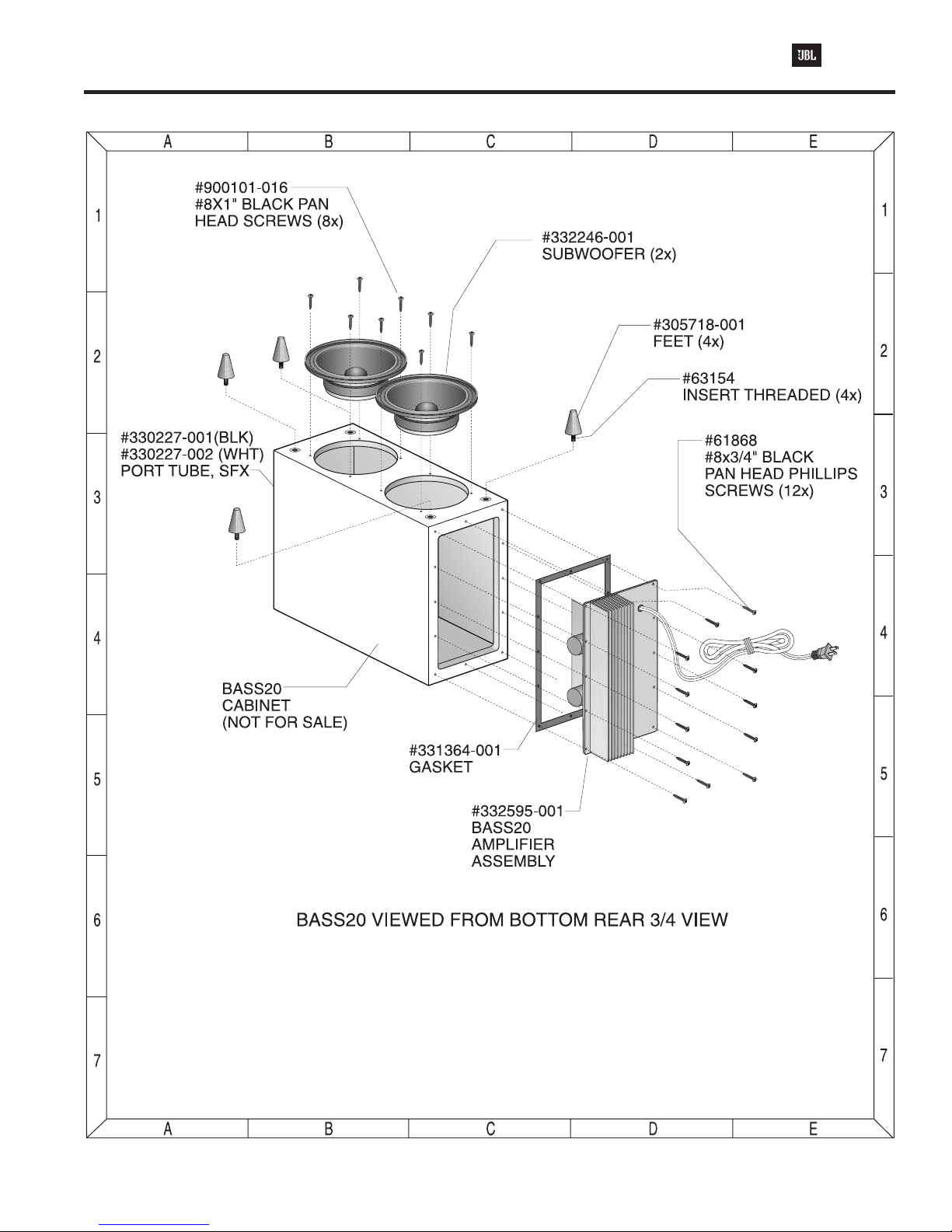
8 PM1366 GASKET FOR BASS20 1
9 TE1125 TERMINAL ULTRA FAST INS. 9
10 WI1637 WIRE #18 BLUE/WHITE TRACER 3"
11 SC1192 Sc 6-32x7/8 TAPT-THR HEX W 2
12 WA1049 WASHER EXT. TOOTH #6 ZINC 6
13 XX1250 STRAIN RELIEF SPT-1 BLACK 1
15 SC1215 SCREW M3x1.25x10 plas-Thr Pan 5
17 XX1174 AC CORD. 6FT UL/CSA APRO. (120V)1
WI1597 AC CORD. 6FT UL/CSA APRO. (230V)1
18 SP1020 SIL. FOAM 3/8"Lx1/4"Wx3/16 2
19 SP1073 SIL PAD TO-3P 1.0"x0.75" 4
20 XX1257 COVER PLASTIC 1
21 XX1259 KNOB BLACK CUSTOM 1
22 WA1032 WASHER PLAIN #6 ZINC FINISH 4
23 SC1194 Sc 6-32x3/8 TAPT-THR HEX 4
331364-001 GASKET 1
61868 Sc #8x3/4" Blk Pan Head Phillips 12
305718-001 FOOT 4
63868 INSERT THREADED (for foot)
332246-001 SUBWOOFER 2
900101-016 SCREW #8x1" Blk Pan Head 8
C01076 RCA JACK DUAL GOLD RED/WHT 1
C01256 JACK SPEAKER QUAD PC 2
CT, LINE 1 TE1175 TRMNL MALE TAB 0.32"x0.25" PI 3
LINE 2
ELECTRICAL PARTS LIST
Capacitors
C1, C2 CP1635 CAP ALUM EL 4700uF 20% 63v 2
C3, 20 CP1473 CAP CERAMIC 220 pF 50V P 2
C4, 24, 30 CP1415 CAP ALUM EL. 2.2uF 20% 50V P 6
31, 32, 33
C5 CP1439 SMD CAP 33nF 10% 100V X7R PI 1
C7 CP1633 CAP CERAMIC 0.033uF 5% 50 PI 1
C8, 10, 13 CP1552 SMD CAP 0.1uF 20% 100V Z5U P 3
C9, 12, 27, 29 CP1417 CAP ALUM EL. 22uF 20% 16V P 4
C11 CP1178 CAP POLY FILM 22nF 5% 63V P 1
REF. NO. PART NO. DESCRIPTION QTY
C14, 16 CP1426 SMD CAP 0.1uF 20% 50V Z5U P 2
C15 CP1479 SMD CAP 3300pF 10% 100V X PI 1
C19, 28 CP1645 CAP AL EL 22uF 20% 63V 85 PI 2
C21 CP1478 SMD CAP 330pF 5% 100V NPO P 1
C22 CP1475 SMD CAP 33pF 5% 50V NPO 12 P 1
C23 CP1411 CAP ALUM EL. 100uF 20% 16V P 1
C1P CP1426 SMD CAP 0.1uF 20% 50V Z5U P 1
C2P, C3P CP1480 SMD CAP 470pF 5% 100V NPO 2
C4P CP1552 SMD CAP 0.1uF 20% 100V Z5U P 1
C5P, 6, 17 CP1579 33µF 16V NPE 3
CX CP1808 0.1µF 250V 1
CX1, CX2, CP1844 0.01µF 200V SMD 4
CX3, CX4
Diodes
CR1, 2, 3, 4 DI1005 1N5401 DIODE 3A/200V P 4
D1, 2, 3, 4, 5 DI1132 SMD DIODE 1N4148 LL-34 PKG T P 5
Z1, 2 DI1150 SMD ZENER 15V 5% CP PKG T P 2
Fuses
F1 (120V) 870-0052 FUSE Fast Blow 5A 250V 3AG 1
F1 (230V) 870-0017 FUSE Fast Blow 2A 250V 3AG 1
F2 FS1073 FAST BLOW 8A 250V ACG 1
(early versions)
F2 312004 FAST BLOW 4A 250V ACG 2
(later versions)
Integrated Circuits
IC1, 2, 3, IC1041 IC SMD DUAL J-FET NJM072B 5
4, 5 OP AMP
Resistors
J1, 2, 3, 4, 5, RS1779 SMD RES ZERO ΩJUMPER 12 P 8
6, 7, 10
P1 RS1794 POT, 50KΩ20% LOG TAPER 1
R1, 2, 4, 5, RS1702 SMD RES 100KΩ5% 1/8W 12 P 8
24, 42,
57, 58
R3, 8, 14, 18 RS1701 SMD RES 10KΩ5% 1/8W 120 P 15
21, 23, 27,
32, 38, 39,
45, 50, 52,
53, 54
R6, 7, 31, 48 RS1700 SMD RES 1KΩ5% 1/8W 12 P 4
R9, 10 RS1720 SMD RES 200KΩ1% 1/8W 1 PI 2
R11 RS1872 SMD RES 51KΩ5% 1/8W 120 P 1
R12 RS2101 SMD RES 24KΩ5% 1/8W 120 PI 1
R13, 15 RS1704 SMD RES 22KΩ5% 1/8W 120 P 2
R16, 49 RS1715 SMD RES 5.6KΩ5% 1/8W 1 P 2
R17 RS1883 SMD RES 1.5KΩ5% 1/8W 12 P 1
R19 RS1878 SMD RES 10Ω5% 1/8W 120 P 1
R20, 40 RS1829 SMD RES 160Ω5% 1/8W 12 P 2
R22, 33, 34 RS1705 SMD RES 4.7KΩ5% 1/8W 12 P 3
R25 RS1831 SMD RES 7.5KΩ5% 1/8W T/ P 1
BASS 20 PARTS LIST