JBL BASSPRO User manual

BassPro
Powered Subwoofer
SERVICE MANUAL
JBL Consumer Products
250 Crossways Park Dr.
Woodbury, New York 11797 Rev0 5/2003

CONTENTS
SPECIFICATIONS . . . . . . . . . . . . . . . . . . . . . . . . . .. . . . . .. . . . . . . . . .. . . . . . . 1
DETAILED SPECIFICATIONS. . . . . . . . . . . . . . . . . . . . . ………….. . . . . . . . . . 2
CONNECTIONS . . . . . . . . . . . . . .. . . . . . . . . . . . . . .. . . . . . . . . . .. . . . . . . . . . 3
CONTROLS & FUNCTIONS. . . . . . . . . . . . . .. . . . . . . . . . . . . . . .. . . . . . . . . . . 5
REMOTE LEVEL CONTROL. . . . . . . . . . . . . .. . . . . . . . . . . . . . . .. . . . . .. . . . . 6
BASIC TROUBLESHOOTING. . . . . . . . . . . . . .. . . . . . . . . . . . . . ... . . . . . . . . . 7
EXPLODED VIEW. . . . . . . . . . . . . . . . .. . . .. ……. . . .. . . . .. . .. .. . . . . …... … . 8
BLOCK DIAGRAM . . . . . . . . . . . . . .. . . . . . . ……... . . . . . . .. . .. . . . . . . . …... 9
PCB DRAWINGS. …………… . . . . ………………………………………………. . 10
ELECTRICAL PARTS LIST …………. .... . .. …. . . . .……….. . . . . . .. .. . . . . . . 13
IC – TRANSISTOR PINOUTS . … . . .. . . . …. . . …….…………... . …. . . . . . . . 15
SCHEMATIC DIAGRAMS . . . . . . . . .. .. .. .. . . ….. .. . ….………... . . . . . . . . . . .16
PACKING ………………. . . . . .. . . . . . . . .. .. . …… . .. .. . . . . . . . . … . . . . . . . . 17
BASIC SPECIFICATIONS
Amplifier power: 100 Watts
Frequency response: 20Hz – 120Hz
Fuse rating: 20A
Max current draw: 12A
Idle current draw: <800mA
Input sensitivity: 50mV to 4V Line-level input; 1V to 16V universal interface
Crossover frequency: 70Hz – 120Hz
Crossover slope: 12dB
Dimensions (L x W x H): 16-1/8" x 9-1/2" x 12-1/4" (includes mounting feet)
(410mm x 242mmx 312mm)

BASSPRO AUTO SUBWOOFER SPECIFICATIONS
GENERAL CONDITIONS: TEST INPUT SIGNAL FOR LINE IN – 2CH/60Hz/250mV.
TEST OUTPUT – 1 W ATT 4 Ohms LOAD (Bridge).
POWER SOURCE DC14.4V/12A min
TEST CONDITIONS: ALL TEST SIGNALS FROM LINE IN UNLESS OTHER REMARKS.
CROSSOVER VR AT MAX POSITION UNLESS OTHER REMARKS.
UNIT NOMINAL LIMIT
1. TOTAL OUTPUT POWER W 100
W 22 20
2. OUTPUT POWER (1 CHANNEL)
(60, 400; 5.0% THD)
% 0.3 0.5 MAX
3. THD AT 1.0W (60,250;)
dB 70 65 MIN
4. SIGNAL TO NOISE RATIO
(60,250; O/P=1W;)
(60-120HZ) dB 60Hz 0REF
5. FREQUENCY RESPONSE
(-- , 250; O/P=1W) 120Hz -1.6+/-3
180Hz -6.5+/-3
MAX TO MIN dB -12+/-3
6. CROSSOVER RANGE
(120,250,O/P=1W,MAX REF)
7. CROSSOVER SLOPE dB 12
LOW – INPUT mV 340 +/- 60
8. INPUT SENSITIVITY
(60, --;O/P=18W,L+R, GAIN MAX)
(60, --;O/P=18W, 2CH,GAIN MAX) HI – INPUT V 3.5 +/- 0.6
mV 0.8 1.5 MAX
9. MAX GAIN NOISE, GAIN MAX )
mV 0.5 0.9 MAX
10. MIN GAIN NOISE, GAIN MIN )
AUTO ON LEVEL V 1.8 +/- 0.5
11. AUTO SENSE
(--, --, HI-N, 1CH) AUTO OFF TIME MIN 3.0 +/- 1.5
12. PROTECTION CIRCUIT
(60,250,O/P=10W) SHORT SPK TERMINAL +/- Functional
13. FUSE RATING A 20
14. MAXIMUM CURRENT DRAW A 12
15. IDLE CURRENT DRAW mA <800
16. DIMENSIONS 16 1/8 X 9 ½ X 12 ¼”
(410 X 242 X 312MM)

POWER CONNECTIONS
Connecting power to BassPro is
shown in Figure 7. Please observe
the following installation tips:
When using the high-level input con-
nections, BassPro will automatically
turn on when you turn on your radio.
In this case, the remote (REM) con-
nection is not needed. Use at least #20
AWG speaker wire for speaker-level
input connections.
Use at least #12 AWG wire for the
Positive Battery (BATT +12) and Ground
()connections. If needed, use at
least #20 AWG wire for the remote
(REM) turn-on connection.
Connect BassPro’s “BATT +12V”
terminal directly to the battery’s posi-
tive (+) terminal. Install a fuse holder,
with a 20A fuse, within 18" of the bat-
tery’s positive (+) terminal.
BassPro
(right-side panel)
Chassis Ground
(Bare Metal)
Source Unit
Battery
Fuse 20 A 18"
Remote
Turn-On
Route all power wires through a grom-
met in the vehicle’s firewall. If a factory
grommet is not available, install one.
Connect a short ground wire from
BassPro’s ground terminal ( ) to the
nearest bare metal surface. For a good
connection, use sandpaper to clear
paint from the metal surface and use
a screw with a lock (star) washer.
The remote (REM) connection requires
a +5 to +12 Vdc signal for BassPro
to turn on when using the line-level
connections. Most head units with
preamp outputs provide this remote
voltage signal. As an alternative,
connect this terminal to a switched
ignition circuit.
Figure 7.
Chassis Ground
(Bare Metal)
Battery
Source Unit
Remote
Turn-On
Fuse 20A 18"
BassPro Connection Panel
3

APPLICATIONS
BassPro is equipped with two line-
level (RCA) inputs and two high-level
inputs. To help you plan the installation
of BassPro, we have included two
system application diagrams in
Figures 8 and 9. For more installation
suggestions, contact your local
authorized JBL car audio dealer.
Splices
(not supplied) Splices
(not supplied)
Figure 9. Line-level connections with
two outputs (single full range or sub-
woofer).
Figure 8. High-level connections.
Connect BassPro’s high-level
inputs to either the front or rear
speaker outputs of your head unit
(splice crimps not included).
BassPro
Connection Panel
Subwoofer Level Control
BassPro
Connection Panel
Subwoofer Level Control
Left Speaker Right Speaker
Source Unit
Source Unit
LF Speaker RF Speaker
LR Speaker RR Speaker
RCA Stereo Cables
(not supplied)
4

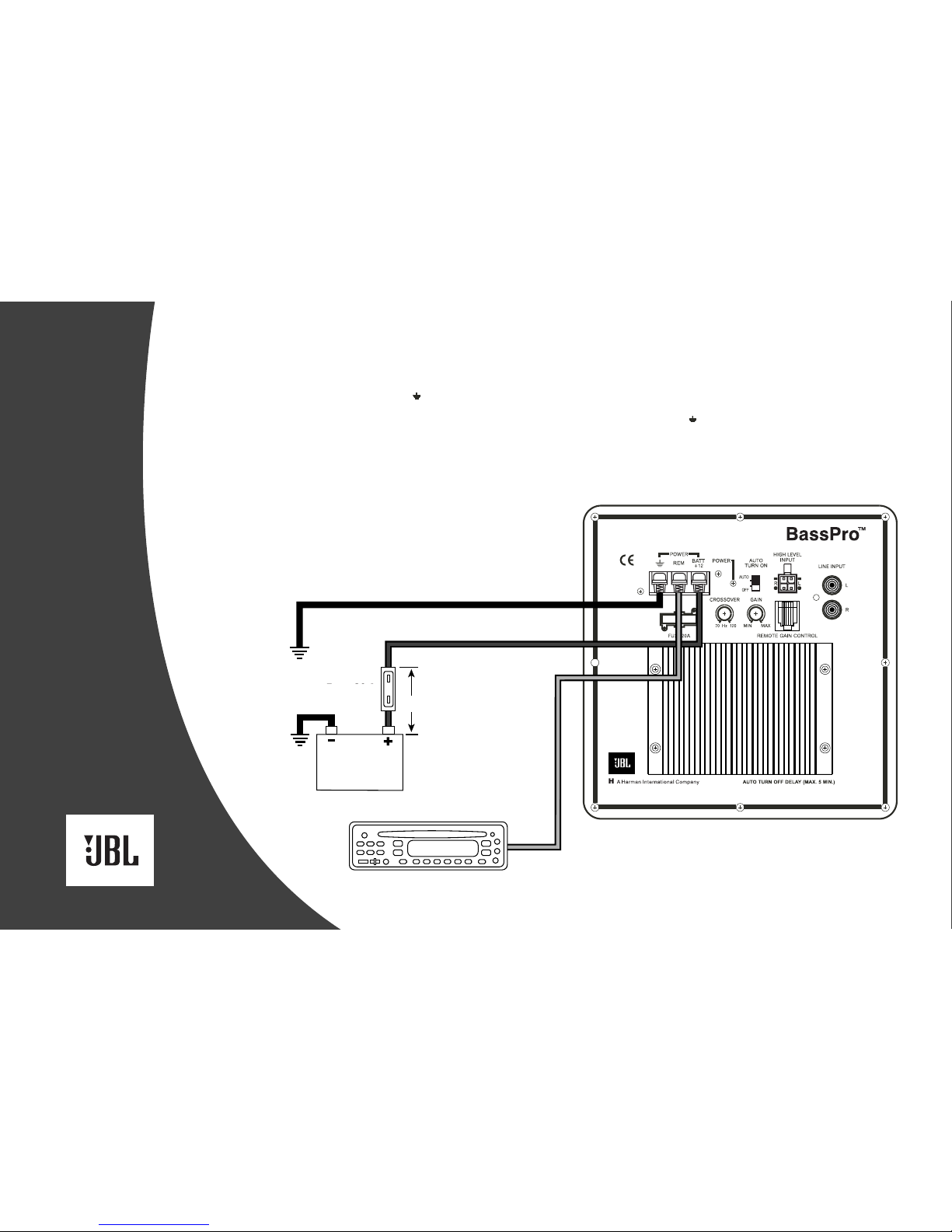
CONTROLS AND FUNCTIONS
BassPro has controls and indicators
that help simplify sonic integration with
almost any vehicle’s unique acoustic
properties. These controls are located
on the amplifier panel, as shown in
Figure 10.
Power LED
Gain Control
Crossover
Remote Bass Control
Auto Turn-On
POWER LED: This indicator
will glow red when the BassPro is
operating.
GAIN CONTROL: Use this
control to adjust the relative volume
(loudness) of BassPro with the other
speakers in the vehicle.
CROSSOVER: Use this control to
adjust the amount of high-frequency
information present in BassPro’s out-
put. A lower value signifies less high-
frequency content.
3. Turn the head unit ON and play a
selection of your favorite music
track that has substantial bass.
4. Adjust the CROSSOVER control
counterclockwise, until you hear
only low-frequency information.
Example – you should not hear
vocals coming from BassPro when
seated in the normal listening
position.
5. Adjust the BASS CONTROL either
clockwise or counterclockwise to
suit your taste, and to avoid audible
distortion.
6. If you elect to not install the Remote
Bass Control, adjust the GAIN
control to the maximum level that
provides undistorted output from
the BassPro, with the head unit’s
volume control at its 3 o’clock
setting.
Note: In most cases the above steps
will provide you with satisfactory
results. However, the actual process
may require several readjustments
of each control, since the settings
will interact with one another. If
necessary, consult your authorized
JBL car audio dealer for help in
tuning your system.
AUTO TURN-ON: For speaker-
level connections, used this switch to
activate (or deactivate) BassPro’s
automatic turn-on circuit. For most
speaker-level applications, slide the
switch to the AUTO position. If you
prefer to use the remote (REM)
connection, slide the switch to the
OFF position.
REMOTE BASS
CONTROL: Use this RJ-11 jack
to connect the supplied remote bass
control.
SETTING THE CONTROLS:
1. Make sure the head unit is off and
VOLUME control is set to minimum.
2. On BassPro’s amplifier panel, set
the CROSSOVER to its maximum
frequency of 120Hz, as shown in
Figure 10.
Note: If using the REMOTE BASS
CONTROL, set GAIN to maximum
and set the BASS CONTROL to the
midpoint.
5
Figure 10.

INSTALLING THE REMOTE CONNECTING THE SUBWOOFER
LEVEL CONTROL TO BASSPRO
The Subwoofer Level Control may be
mounted under the dash or dismantled
and mounted in the dash for a factory-
installed appearance.
UNDER-DASH MOUNTING
Select a mounting location that allows
easy access to the control while driv-
ing. Using the Subwoofer Level Control
as a template, mark and drill holes in
the mounting surface. Attach the
Subwoofer Level Control using the
mounting screws provided (Figure 4).
IN-DASH MOUNTING
Disassemble the Subwoofer Level
Control by removing the two Phillips-
head screws on the front panel,
rear panel and on top. Remove the
Subwoofer Level Control’s bottom and
side panels. Slide the Subwoofer Level
Control’s PC board forward to release
the RJ11 connector from the back
panel and remove the board along with
the potentiometer, knob and connector
as a single assembly.
Choose a mounting location that
allows easy access to the control,
and provides 1-3/4" clearance behind
the mounting surface. Drill a 9/32"
hole in the mounting surface. Feed
the Subwoofer Level Control’s
potentiometer shaft (with the knob
removed) through the hole and use the
nut and washer provided to hold the
control in place (Figure 5).
Route the cable behind the dash or
other interior panels and under the
carpet. Do not route the cable outside
the vehicle. Connect the RJ11 cable
between the RJ11 receptacle on the
BassPro and the receptacle on the
Subwoofer Level Control (Figure 6).
Socket
for
Control
Cable
Level
Control
Circuit
Board
Washer
Hex Nut
Knob
BassPro Connector Panel
Figure 4. Under-dash mounting of the
Subwoofer Level Control.
Figure 5. In-dash mounting of the Subwoofer
Level Control.
Figure 6. Subwoofer Level Control electrical
connection.
Knob
Hex Nut
Washer Level-
Control
Circuit
Board
Socket
for
Control
Cable
BassPro Connection Panel
Control
Cable
Rear View of
Level-Control
Circuit Board
6

TROUBLESHOOTING
PROBLEM CAUSES AND SOLUTIONS
POWER LED not lit. 1. Fuse is blown and needs
replacement.
2. Head unit not functioning properly.
3. Check remote turn-on, power and
ground connections.
POWER LED is lit but there is no bass. 1. Inputs are not connected. Check
connections.
2. Head-unit fader controls are not set
properly. Adjust head-unit controls to
feed audio signals to BassPro.
3. Incorrect GAIN control setting.
Output sounds muddy or distorted. 1. GAIN is set too high.
2. Bass level is set too high on head
unit.
3. Head unit output is distorted or
blown. See your authorized JBL car
audio dealer.
Output gets louder when the head-unit Using speaker-level connection: one of
balance is adjusted to L or R. the speaker connections is reversed
(+/–). Reverse one channel.
POWER LED remains ON after system Speaker-level connections have a five-
is turned off. minute turn-off delay. Check the unit at
a later time.
7

Ref.
#
Description Part Number Qty
1 Enclosure 241-060-00587 1
2 Side Baffles 301-ABS-00353 2
3 Logo 316-ABS-00538 2
4 Port Tube 249-ABS-00148 1
5 Right Bracket 325-ABS-00421 2
6 Left Bracket 325-ABS-00420 2
7 Plug (Screw Cap) 338-ABS-00126 8
8 Screw 351-FM04039A572 8
9 Screw 352-HM04014D611 8
10 Woofer (DCR = 3.6Ωx 4) 16PF11BZW-AW01 1
11 Screw 325-FM04018A576 4
12 Amplifier Not For Sale 1
13 Screw 352-FM04019D470 8


BassPro Electrical Parts List
PART NO. DESCRIPTION QTY REFERENCE DESIGNATOR
Semiconductors
190-06m4558l I.C. NJRC NJM4558L Dual Op-Amp 1 U1
190-14m13700n I.C. NS LM13700 Dual Op-Amp 1 IC301
190-16a73770 I.C. TDA7377 Power Amp 2 IC101,121
192-027c1815gr Transistor 2SC1815GR NPN 3 Q31,40,301
192-028a1015gr Transistor 2SA1015GR PNP 3 Q32,41,42
195-10204hd LED RED 3mm 1 PWR
197-101n5402 Diode 1N5402 1 D1
197-131n4148 Diode 1N4148 5 D2,4,40,41,42
199-15000515 Zener Diode 5.1V 1/2W 52mm 2 D5,D6
199-15000625 Zener Diode 6.2V 1/2W 1 D3
Resistors
110-16102j26 Resistor 1K 1/6W ±5% CF 4 R01,25,32,40
110-16103j26 Resistor 10K 1/6W ±5% CF 8 R11,13,20,44,102,305,307,312
110-16105j26 Resistor 1M 1/6W ±5% CF 1 R45
110-16151j26 Resistor 150Ω1/6W ±5% CF 1 R311
110-16153j26 Resistor 15K 1/6W ±5% CF 2 R304,309
110-16154j26 Resistor 150K 1/6W ±5% CF 2 R42,310
110-16224j26 Resistor 220K 1/6W ±5% CF 1 R14
110-16273j26 Resistor 27K 1/6W ±5% CF 1 R16
110-16275j26 Resistor 2.7M 1/6W ±5% CF 1 R46
110-16303j26 Resistor 30K 1/6W ±5% CF 1 R306
110-16332j26 Resistor 3.3K 1/6W ±5% CF 1 R26
110-16333j26 Resistor 33K 1/6W ±5% CF 1 R21
110-16393j26 Resistor 39K 1/6W ±5% CF 1 R15
110-16472j26 Resistor 4.7K 1/6W ±5% CF 1 R31
110-16473j26 Resistor 47K 1/6W ±5% CF 1 R33
110-16474j26 Resistor 470K 1/6W ±5% CF 2 R43,34
110-16511j26 Resistor 510Ω1/6W ±5% CF 2 R302,303
110-16513j26 Resistor 51K 1/6W ±5% CF 1 R0
110-16514j26 Resistor 510K 1/6W ±5% CF 1 R47
110-16681j26 Resistor 680Ω1/6W ±5% CF 1 R23
110-16682j26 Resistor 6.8K 1/6W ±5% CF 2 R1,2
110-16822j26 Resistor 8.2K 1/6W ±5% CF 2 R30,301
110-16913j26 Resistor 91K 1/6W ±5% CF 2 R3,4
110-20101j20 Resistor100Ω2W ±5% 20mm 4 R5,6,7,8
115-v203b101 Variable Resistor R0901N-JMD1-B20K 1 R10
115-v203b202 Variable Resistor R0901G-2KDQ-B20K 1 R12
116-161101f26 Resistor 1.1K 1/6W ±1% MF 1 R22
Capacitors
130-2b102k503 Disc Cap. 1000P 50V ±10% 5 C2,01,02,42,43
130-2f104z503 Disc Cap. 0.1U 50V +80/-20% 8 C15,17,26,28,107,125,306,307
132-103j503 Mylar Cap. 0.01U 50V ±5% 2 C29,30
132-104j503 Mylar Cap. 0.1U 50V ±5% 3 C6,7,25
135-3105m50 Electrolytic Cap. 1U 50V ±20% 7 C5,21,22,23,24,40,303
135-3106m50 Electrolytic Cap. 10U 50V ±20% 5 C1,8,13,109,301
135-3108m16 Electrolytic Cap. 1000U 16V ±20% 1 C14
135-3227m16 Electrolytic Cap. 220U 16V ±20% 1 C27

PART NO. DESCRIPTION QTY REFERENCE DESIGNATOR
135-3475m50 Electrolytic Cap. 4.7U 50V ±20% 1 C304
135-3476m50 Electrolytic Cap. 47U 50V ±20% 3 C41,102,123
135-4338m25 Electrolytic Cap. 3300U 25V ±20% 1 C16
Miscellaneous
120-12101k3 Inductor 100UH 1/2W 1 L2
122-14050k4160 Inductor Ferrite 5uH 15A CR630*5R0KUM 1 L1
154-k020a800 Fuse 20A 32V ATC UL/CSA 1 F1
155-9f30240 Fuse Holder F30240100P 1 F1
162-a040d001 SPEAKER WIRE #1015 400mm 4
162-a5000001 4C WIRE 5M BLK 1
174-0rcb202ha JACK 2PIN RCB-202HAG INPUT 1 JK1
174-5te112j DC JACK TE1-12J POWER 1 JK3
174-9mjd0604 M/JACK D/S 6P4C 1 M104
175-1d02v01 Wire connector 2PIN pitch=3.96mm 4 CH1,2,3,4
175-9h04v01 Wire connector 4PIN pitch=4.2mm 1 JK2
180-p752209 SWITCH SSP752209-25JJ1 AUTO-ON 1 SW40
LEVEL CONTROL ASS
Y
015-AA00-00110 LEVEL CONTROL ASSY (COMPLETE) 1
311-ABS-00237 KNOB 1
115-h203a203 POTENTIOMETER 1
166-AL035081 CONTROL CABLE 1


Other manuals for BASSPRO
5
Table of contents
Other JBL Subwoofer manuals

JBL
JBL STADIUM 1024 User manual

JBL
JBL P1020DII User manual

JBL
JBL P-1200 Instruction manual

JBL
JBL CONTROL SUB 10 User manual

JBL
JBL MPS-1000 User manual

JBL
JBL MPC-X100 Programming manual

JBL
JBL GTO 804 8" Instruction manual

JBL
JBL GTO1204D Instruction manual

JBL
JBL HLS 820 User manual

JBL
JBL GT102 User manual

JBL
JBL W10GTI Instruction manual

JBL
JBL Grand touring series User manual

JBL
JBL PowerBass PB12 User manual

JBL
JBL P-1500 Instruction manual

JBL
JBL PS1400 User manual

JBL
JBL CS1014 User manual

JBL
JBL Cinemavision CVSUB50 User manual

JBL
JBL MS-BassPro SQ User manual

JBL
JBL PRX900 Series User manual

JBL
JBL SUB 560P User manual