5
G SERIES LOUDSPEAKERS
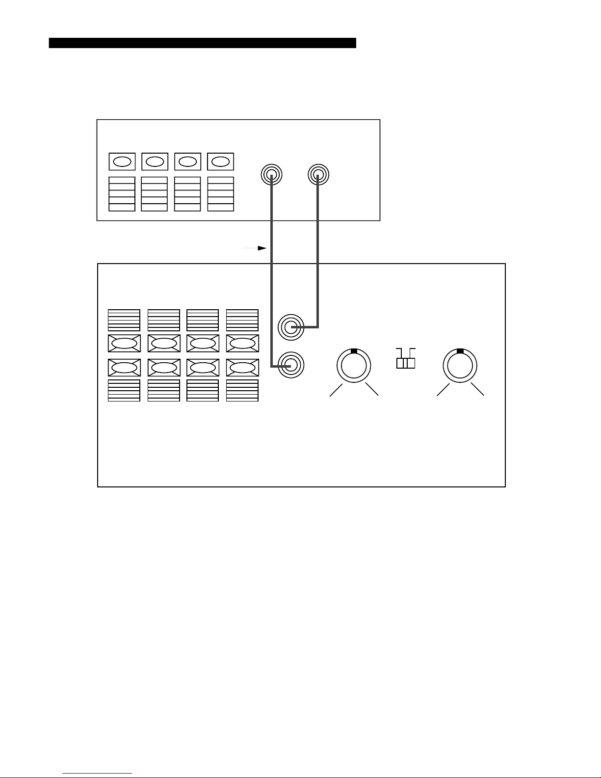
be sent to your main speakers or
satellites. Your G Sub10 subwoofer
can use the signal from your
receiver/TV/source amplifier to
produce the low bass while passing
the unaltered signal source to the
external speakers.
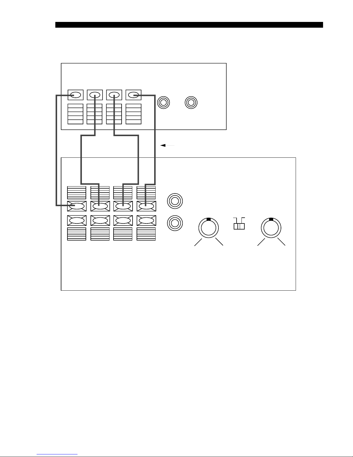
Speaker Level Output (to external
speakers) –Hook up the external
speakers using two-conductor
insulated wire using the same
procedure as described in “Speaker
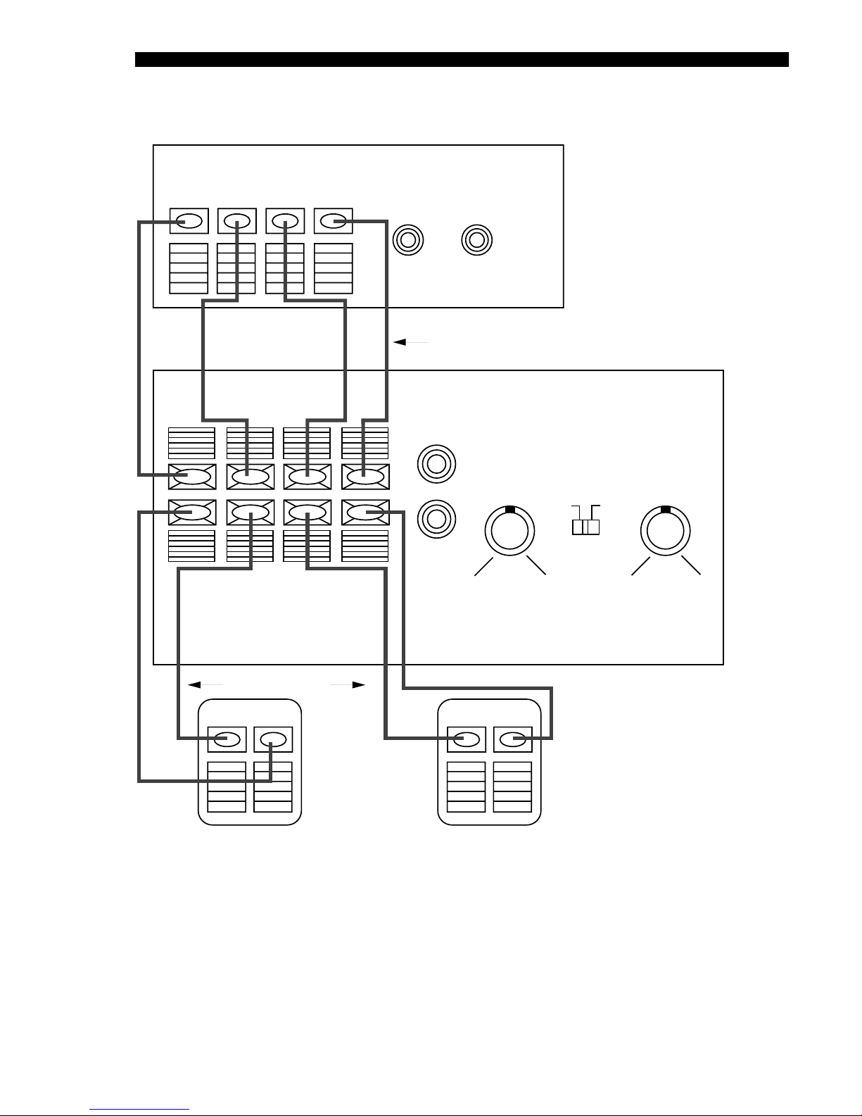
Level Input”section. The red (+)
terminal of the subwoofer should be
connected to the red (+) terminal of
the external speaker, and the black
(–) to black. Connecting the external
speakers in this manner ensures that
they will be in phase; that is, work
together rather than in opposition.
Connecting the speakers out of phase
will not damage them, but will result
in less bass and poor imaging
(see Figure. 3).
NOTE: There is no significant change
in impedance loading to your
receiver/TV/source amplifier
when hooking up through the
G Sub10 subwoofer.
LEVEL
NOTE: When first setting up your
subwoofer, set the Level control
counterclockwise to "Min" (minimum)
before turning power switch ON.
Turn power switch to “On,”and use
the "Level" knob to add the
appropriate amount of bass to your
main speaker output. Increase the
subwoofer level by turning the level
knob clockwise until you find a setting
that is pleasing to you.
CROSSOVER
FREQUENCY
Use the "Crossover Freq" knob
to adjust the upper end of the sub-
woofer's frequency response. The
crossover control determines the
highest frequency your subwoofer will
reproduce. It allows a seamless
transition from subwoofer to satellite
speakers. When using small satellite
speakers (without much bass), you
would want the crossover frequency
more toward the upper end (200 Hz)
to fill in the sound your satellites can't
reproduce. When using larger main
speakers, a setting more toward the
low (50 Hz) end gives a smoother
transition from your subwoofer to your
main speakers. Experiment until you
find a setting that meets your
satisfaction.
MULTICOLOR LED
INDICATOR OPERATION
The LED on the rear amp plate
signifies the following operation states
of the G Sub10 subwoofer:
RED –When your subwoofer isn't
receiving a music or source signal
and the power switch is turned on, the
LED indicator turns RED telling you
that the unit is plugged in and ready
for operation. At this time, the
amplifier is in a "Standby" mode,
effectively turned off and waiting for a
signal from the source amplifier.
GREEN –When your subwoofer,
picks up a source signal, it turns on
instantly and begins to play. The LED
turns GREEN. After about 6 to 8
minutes of non-use (no signal being
received), your subwoofer goes into
the auto shut-off mode. The LED
turns RED to signify this "Standby"
condition.
NOTE: When the amplifier is in the
“Standby” mode it is effectively turned
off. The Red LED tells you that the
subwoofer is plugged into the AC wall
power with its power switch turned on,
but the amplifier circuitry is not
engaged. You do not have to reach to
the back panel and turn the power
switch off after every use. Your
G Sub10 subwoofer turns itself off
internally. For extended periods of
non-use (i.e., vacations, etc.), you
may wish to actually turn the
subwoofer off using the power switch.