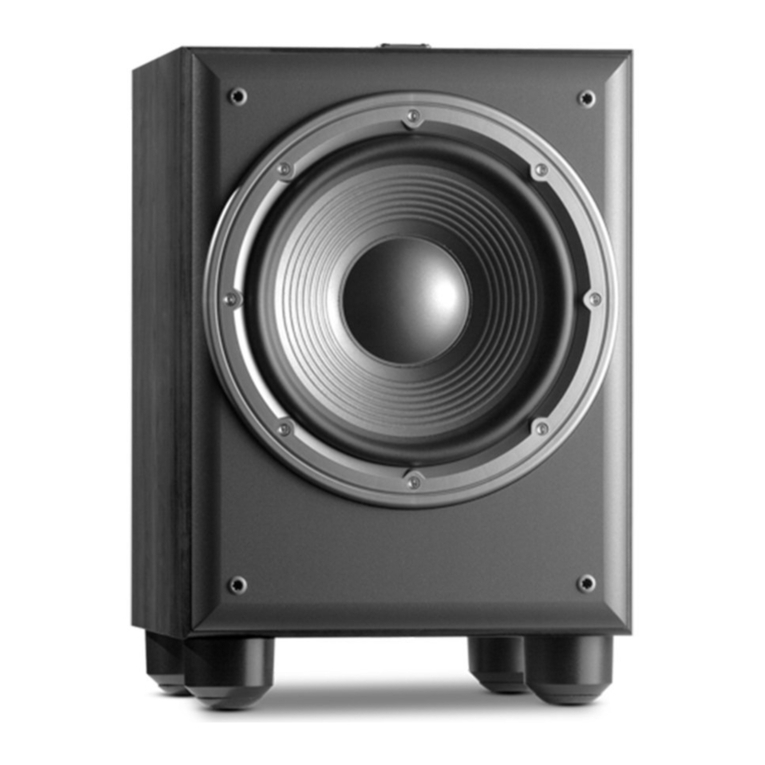
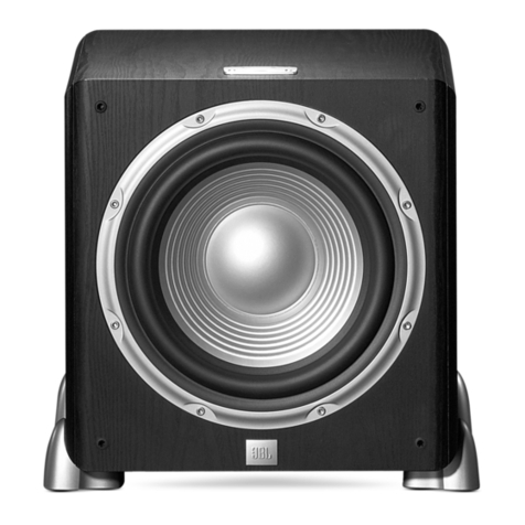
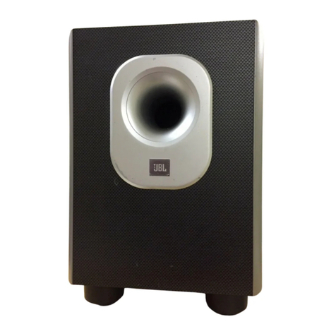
JBL CONTROL SUB 6 User manual

SERVICE MANUALSERVICE MANUAL
/
Sub 6/10
This Service Manual covers
the Sub6 and Sub10 models
JBL Consumer Products
250 Crossways Park Dr.
Woodbury, New York 11797 RevB 7/2003

1
Powered Subwoofer SUB 6/10
TABLE OF CONTENTS
SPECIFICATIONS..........................................................1
FEATURES.....................................................................1
SUB6/10 DISASSEMBLY PROCEDURES....................2
SUB6/10 CONTROLS ....................................................3
TEST PROCEDURE ......................................................4
SUB6/10 POWERED SUB WOOFER TEST SETUP ...4
SUB 6/10 BLOCK DIAGRAM ........................................5
SUB 6/10 EXPLODED ASSEMBLY VIEW....................6
SUB6 PART LISTS .......................................................9
SUB10 PART LISTS ....................................................12
SUB 6/10 PACKAGING ...............................................15
PRINTED CIRCUIT BOARDS .....................................16
INTEGRATED CIRCUIT DIAGRAMS ..........................19
SUB6 WIRING DIAGRAM ...........................................22
SUB10 WIRING DIAGRAM .........................................23
SUB 6/10 SCHEMATIC DIAGRAM ............................24
SPECIFICATIONS
SUB6 SUB10
Amplifier Power (RMS) .....60Watts .......100Watts
Woofer Size .........6-1/2” ........10”
Inputs ...........Line and Speaker Level . . Line and Speaker Level
Outputs ..........High Pass Speaker Level . . High Pass Speaker Level
Crossover Frequency .....90Hz - 200Hz .....90Hz - 200Hz
(continuously variable)
Frequency Response......40Hz - (90Hz - 200Hz)* . . 38Hz - (90Hz - 200Hz)*
*Determined by crossover setting
External Dimensions
Height ...........17"(432mm) ......24”(608mm)
Width ...........12-3/4” (324mm).....17-3/4” (450mm)
Depth ...........11-1/8” (282mm).....13-1/2” (342mm)
Weight ...........26lbs/11.8 kg .....48lbs/21.8 kg
FEATURES
nRugged molded plastic front baffle
nAdjustable crossover point
nAdjustable volume control
nSpeaker and Line Level inputs
nAuto turn-on/turn-off
JBL continually strives to improve its products. New materials, production methods and design refinements are introduced into
existing models without notice as a routine expression of our design philosophy. For this reason, Sub 6/10 may differ in some
respect from their published specifications and descriptions, but will always equal or exceed the original specifications unless
otherwise stated.

2
Powered Subwoofer SUB 6/10
SUB6/10 DISASSEMBLY PROCEDURE
1. Unplug all external connecting cables.
2. Place the subwoofer on a padded surface so that the
controls are facing upwards.
3. Remove (2) ¾” Philips screws (S4) holding the
control panel in place.
4. Remove (6) ½” Philips screws (S4) holding the
heatsink/amplifier in place.
5. Remove both assemblies partially out of the cabinet
and rest them on the cabinet surface; no additional
connectors need to be removed as this should be
sufficient for most servicing, although driver damage
may result from using the woofer for a load during
testing. Following Page 4 (Driver Function) Step 1 to
remove woofer and replace with a 4 ohm 100W
Resistor if necessary.
6. For further disassembly - Remove the three
remaining molex connectors CN301 or CN301A,
CN306 & CN902A from the board(s), cutting the tie
wraps holding the cables in place. Remove board
assemblies.
7. Turn the subwoofer over so that the input connectors
face upward; remove the (8) 1” Philips screws (S2)
on the input plate; remove the (2) ½” Philips screws
on both sides of the High Level Input Connectors.
8. Pull plate away from the cup and cabinet, exposing
components.
9. Removal of power transformer: Remove the ½”
plated screws holding the small oval cover inside the
input cup; remove cover.
10. Cut the cable tie and remove/cut the wires nuts
attaching the transformer wires to the power cord.
11. Pull on entire input assembly, including cup, away
from cabinet - there may be enough slack in the
wires to expose the inner cabinet and connectors.
If not, you must enter through the woofer opening;
cut the tie wrap to the gray cable and unplug molex
connector CN305B.
12. Unplug molex connector CN901 attaching transformer
output wires to inner connector board.
13. Remove (4) Philips machine bolts (S7) holding the
transformer to the cabinet; each bolt has a nut (N1)
on the inside of the cabinet that should be held with
a 5/16” nut driver or wrench.
14. Remove power transformer from cabinet.
Reassembly - follow disassembly procedures in reverse
order, replacing cables ties where cut, and wire nuts
when removed.
Sub10 only - when the heatsink/amplifier and control
board is installed, there is a notch in the plastic baffle for
the connecting cables between the two surfaces; make
sure the connecting cables are routed through this notch
or the control panel will not seat properly in its bezel.

3
Powered Subwoofer SUB 6/10
SUB6/10 CONTROLS
1. Volume/Power - This knob controls the volume as well
as the power status of the subwoofer. The Sub6/10
subwoofers incorporate an AutoTurn-On/Off Circuit.
Turn the volume knob completely counterclockwise to
turn the subwoofer OFF.
2. LED - Red/Green. This LED indicates the Mode status
that the subwoofer is in. The LED will light Green
when the Volume knob is turned clockwise to ON.
The LED will light Red when the Volume knob is
turned off (the knob turned fully clockwise) or the
receiver/amplifier has been turned off for five
minutes. The subwoofer will turn on when your
receiver/amplifier begins playing again.
3. Crossover Frequency - The crossover frequency
knob determines the highest frequency your
subwoofer will reproduce. It allows a seamless
transition from the subwoofer to the satellite
speakers.
4. Phase - The phase switch is used to adjust the
relative polarity of the subwoofer.
5. High Level Inputs - These High Level Inputs are for
receivers that do not have line-level “pre-amp out”
or “subwoofer out” jacks. When a pair of main or
satellite speakers are attached to the OUTPUT
terminals, they are driven the full range of
frequencies as generated by the music source
(receiver, amplifier, etc.)
6. Low Level Input - These left and right Line Level
Inputs are normally used when the receiver/
processor has line-level “pre-amp out ” or
“subwoofer out” jacks.
7. Mono/Stereo - This setting of this switch affects the
subwoofer when using the Low Level Input only.
If you are using a dual (stereo) RCA cable, set the
switch to STEREO; if using a single (mono) RCA
cable, plug into the (R) Input Jack and set the switch
to MONO.
8. Low/High - The setting of this switch depends on
which method of Input Connection you will be using.
When using the Low Level Input (RCA Connectors),
set the switch to LOW; when using the High Level
Input (Speaker Connectors), set the switch to HIGH.
9. Fuse - Use only same type of fuses. Use a 3.15A
250V fuse for the 120 volt American version and use
a 4A 250V fuse for the 230 volt European version.

4
Powered Subwoofer SUB 6/10
TEST PROCEDURE
Equipment Needed:
nFunction generator/signal
generator/sweep generator
nIntegrated Amplifier
nMultimeter
nCables - Line level (RCA) and Speaker cables
UUT = Unit Under Test
General Function
1. Connect both left and right line level inputs (RCA) to
signal generator and UUT. When using a mono
source make sure the cable is inserted into the right
input jack and the “mono/stereo” switch is set to
“mono”. Turn Frequency Response control to
maximum (300 Hz).
2. Turn on generator and adjust to 50mV, 50 Hz.
3. Plug in UUT; red LED should be ON. Turn volume
knob full clockwise to turn unit ON for maximum
output.
4. Green LED should light, immediate bass response
should be heard and felt from port tube openings.
5. Turn off generator, turn volume knob all the way
down to OFF, disconnect RCA cables.
6. Connect two pairs of speaker cables to high level
input terminal on UUT. Cables should be connected
to an integrated amplifier fed by the signal generator.
Observe polarity of speaker cables.
7. Turn on generator and adjust so that speaker level
output is 1.2V, 50 Hz.
8. Turn volume knob full clockwise to turn unit ON for
maximum output.
9. Green LED should light, immediate bass response
should be heard and felt from port tube opening.
Sweep Function
1. Follow steps 1-4 above, using a sweep generator
as a signal source.
2. Sweep generator from 20Hz to 300Hz. Listen to the
cabinet and drivers for any rattles, clicks, buzzes or
any other noises. If any noises are heard, remove
driver and test.
Driver Function
1. Carefully pry metal grille out of its recess with a
sharp pointed instrument - USE CAUTION. Remove
all 8-32 x 2” Philips mounting screws; remove woofer
and detach both terminals.
2. Check DC resistance of driver; it should be
Sub6 = 3.4 ohms, Sub10 = 3.0 ohms.
3. Connect a pair of speaker cables to driver terminals.
Cables should be connected to an integrated
amplifier fed by a signal generator. Turn on
generator and adjust so that speaker level output
is 5.0V.
4. Sweep generator from 20Hz to 1kHz. Listen to
driver for any rubbing, buzzing or other unusual
noises.
SUB6/10 POWERED SUB WOOFER TEST SETUP

5

6
Powered Subwoofer SUB 6/10
SUB 6/10 EXPLODED ASSEMBLY VIEW (refer to pages 7 and 10)

7

8

SUB6 PART LISTS
SUB 6-MECHANICAL PARTS LIST
Ref No. Part No. Description Qty.
1 EVM0006-001 WOOD BOX 1
2 J1333B FRONT CAB (BLACK) 1
J1333W FRONT CAB (WHITE) 1
3 J3298A CNTL PANEL 1
4 J3404B PHASE KNOB (BLACK) 1
J3404W PHASE KNOB (WHITE) 1
5 J3402B FREQ. KNOB (BLACK) 1
J3402W FREQ. KNOB (WHITE) 1
6 J3403B VOL. KNOB (BLACK) 1
J3403W VOL. KNOB (WHITE) 1
7 J3400 REAR COVER 1
8 J2093B PORT EDGE 1
9 J2093A PORT TUBE 1
10 K4249 JACK PLATE 1
11 C6093B 6 1/2” WOFFER 1
12 TT11000-001 (100V) X’FORMER 1
TT11200-111 (120V) X’FORMER 1
TT112300-108 (230V) X’FORMER 1
13 K6250 X’FORMER BRACKET 1
14 K6251 X’FORMER PLATE 1
15 K6247 GRILLE (BLACK) 1
K6247W GRILLE (WHITE) 1
16 J3296/K6228A LOGO PLATE 1
17 E4219 AMP PCB ASS’Y 1
18 K6248 HEAT SINK (BLACK) 1
K6248W HEAT SINK (WHITE) 1
19 E4220 JACK PCB ASS’Y 1
20 E4216 VR/LED PCB ASS’Y 1
21 E4218 CON PCB ASS’Y 1
22 GSE0073-002 PCB BRACKET 1
23 E4214B FUSE HOLDER 1
24 47455-058 (100V) LINE CORD 1
47455-052 (120V) LINE CORD 1
2559-022022 (230V) LINE CORD 1
25 E4217 SW PCB ASS’Y 1
N1 HNI1482 NUT FOR PLT+X’FORMER BKT 1
P1 J3297F DRIVER GASKET 1
P2 J3297C PORT GASKET 1
P3 J3297D FRONT GASKET 1
P4 J3297E COVER GASKET 1
P5 J3297A X’FORMER GASKET 1
P6 J3297B AMP GASKET 1
P7 J3297G BAFFLE GASKET 1
S1 F5010 SCREW FOR SPK 8 xM4xL50 8
S2 F2021 SCREW FOR JACK 9
PLATE 9 xM4xL20
S3 F2509 SCREW FOR X’FORMER 9
PLT 9 xM5xL25
S4 F1618 SCREW FOR HEATSINK 9
#5.8 x 16mm L
S5 F1226 SCREW FOR PORT 7
TUBE 7 xM4xL12
S6 F2507 SCREW FOR BAFFLE 8
8 xM4xL25
S7 F1813 SCREW FOR PLT+X’FORMER 4
BKT/PCB BKT TO HSINK
S8 F1014 SCREW FOR JACK PCB/AMP 8
PCB 5.3 xM3xL10
S9 H120301-308 SCREW FOR PCB TO PCB 3
BKT/IC TO HSINK 3 xL8
S10 F1679 SCREW TO CONTROL PANEL 2
#6.3 x 16mm L (Black)
SUB 6-ELECTRICAL PARTS LIST
Ref. No. Part No. Description Qty.
Capacitors
C101-102 PVE3955-332 ELECT 3300 50V 20% 2
C103 PRE3955-101 COND ELECT 100 uF 50V 20% 1
C104, 901 PRE3952-101 COND ELECT 100 uF 16V 20% 2
C105 PRE3955-220 COND ELECT 22 uF 50V 20% 1
C106, 120 PRM3737-333 COND MYLAR 0.033 uF 100V 5% 2
C107 PRE3954-101 COND ELECT 100 uF 35V 20% 1
C108-109 PRE3954-100 ELECT 10 uF 35V 20% 2
C110 PRE3955-478 COND ELECT 0.47 uF 50V 20% 1
C111 PRE3951-101 COND ELECT 100 uF 10V 20% 1
C112-113 PRE3953-101 COND ELECT 100 uF 25V 20% 2
C114 PRD1335-150 COND DISC 15 pF 50V 5% NPO 1
C115, 121 PRM3737-683 COND MYLAR 0.068 uF 100V 5% 2
C116-117, PRM3737-104 COND MYLAR 0.1 uF 100V 5% 6
C305-308
C118, 301, PRD8035-101 DISC 100 pF 50V 5% 6
904-907 I SL D=5
C119, 125 PRE3955-479 COND ELECT 4.7 uF 50V 20% 2
C122 PRM3737-223 COND MYLAR 0.022 uF 100V 5% 1
C123 PRD8035-100 COND DISC 10pF 50V 5% I SL D=5 1
C160 PRE3954-220 COND ELECT 22 uF 35V 20% 1
C302 PRD8035-300 COND DISC 30pF 50V 5% I SL D=5 1
C303-304 PRD3965-104 DISC 0.1uF 50V +80-20% 2
Y5V/Z5V
Control Sub 6/10
9

Ref. No. Part No. Description Qty.
Resistors
R101, 107, QAF0650-332 RESISTOR 3.3K OHM 1/6W 5% CF 4
113, 119
R102, 111, QAF0650-103 10K OHM 1/6W 5% CF 10
132, 133,
140, 174,
178, 905,
906, 907
R103, QAF0650-473 RESISTOR 47K OHM 1/6W 5% CF 3
179, 180
R104, 136 QAF0650-683 RESISTOR 68K OHM 1/6W 5% CF 2
R105, 151 QHM2050-561 RESISTOR 560 OHM 2W 5% MF 2
P=20.0 mm
R106, 117, QAF0650-224 220K OHM 1/6W 5% CF 4
175, 176
R108 QAF0650-123 12K OHM 1/6W 5% CF 1
R109, 110, QAF0650-102 1K OHM 1/6W 5% CF 4
124, 130
R112 QAF0650-105 1.0M OHM 1/6W 5% CF 1
R114, 118, QAF0650-223 22K OHM 1/6W 5% CF 3
122
R115, 154, 172 QAF0650-104 100K OHM 1/6W 5% CF 3
R116 QAF0650-364 RESISTOR 360K OHM 1/6W 5% CF 1
R121 QAF0650-225 2.2M OHM 1/6W 5% CF 1
R125-128, QAF0650-153 15K OHM 1/6W 5% CF 6
144, 147
R131, 135 QAF0650-183 18K OHM 1/6W 5% CF 2
R134 QAF0650-203 20K OHM 1/6W 5% CF 1
R139, 170 QAF0650-222 2.2K OHM 1/6W 5% CF 2
R141 QAF0650-151 150 OHM 1/6W 5% CF 1
R142 QAF0650-122 1.2K OHM 1/6W 5% CF 1
R143 QAF0650-392 RESISTOR 3.9K OHM 1/6 5% CF 1
R145 QAF0650-391 RESISTOR 390 OHM 1/6W 5% CF 1
R148, 155 QHS0250-100 RESISTOR 10 OHM 1/2W 5% 2
R149, 150 QAF0250-100 10 OHM 1/2W 5% CF 2
R152-153 QHE5050-228 RESISTOR 0.22 OHM 5W 5% 2
CEMENT FIXED RES
Ref. No. Part No. Description Qty.
R156 QAF0650-563 RESISTOR 56K OHM 1/6W 5% CF 1
R169 QAF0650-333 RESISTOR 33K OHM 1/6W 5% CF 1
R171 QAF0450-222 2.2K OHM 1/4W 5% CF 1
340X2222934
R173 QAF0650-331 330 OHM 1/6W 5% CF 1
R177 QAF0650-474 RESISTOR 470K OHM 1/6W 5% CF 1
R181 QAF0650-274 270K OHM 1/6W 5% CF 1
R901-902 QHM1050-152 RESISTOR 1.5K OHM 1W 5% 2
METAL FILM
R903-904 QAF0650-154 RESISTOR 150K OHM 1/6W 5% CF 2
RD101 QAF0450-151 150 OHM 1/4W 5% CF 1
SVR101 QAF0650-202 2K OHM 1/6W 5% CF 1
ZD102 QAF0450-560 56 OHM 1/4W 5% CF 1
340X2560934
Diodes
BD101 RHD0402-001 RECTIFIER BRIDGE RS402L 4A 1
D101-105 RAD4001-001 RECTIFIER 1N4001 1A 35VRMS 5
D105-112 RAD4148-001 DIODE SW 1N4148 7
ZD101 RAZ0859-086 DIODE ZENR 17.5-18.3V .5W 1
HITACHI HZ18-2
ZD103 QAF0450-100 10 OHM 1/4W 5% CF 1
340X2100934
Transistors
Q101-105, RAN0945-001 XISTR NPN 2SC945P NEC 11
107, 109,
112, 114,
115, Q120
Q106, 108 RAP0733-001 PNP 2SA733Q,P NEC 2
Q121 RHP1264-001 XISTR PNP 2SA1264N-O TOSHIBA 1
Q122 RHN0882-001 XISTR NPN 2SD882P 1
Q123 RHN3181-001 XISTR NPN 2SC3181N-O TOSHIBA 1
Integrated Circuits
IC101 RHI0740-001 IC 14 PIN TL074CN 1
IC102 RHI4558-001 IC 8 PIN JRC4558D JRC OP AMP 1
SUB6 PART LISTS (continued)
Control Sub 6/10
10

Ref. No. Part No. Description Qty.
IC103 RHI1298-001 IC 14 PIN uPC1298V NEC 50-80W 1
POWER AMP DRV
IC104 RHI7815-001 IC 3 PIN 78L15 REGULATOR 1
POS. 15V 100mA
IC105 RHI7915-002 IC 3 PIN 79L15 REGULATOR 1
NEG. 15V 100mA
Miscellaneous
CN301 CCN1500-A18 CONNECTOR B2B-XH-A 2 PIN 1
GOLD OVER 50 uin
CN305A CCN1500-A42 CONNECTOR S2B-XH-A 2 PIN 1
GOLD OVER 50 uin
CN305A-305B 4999A-274 CON/WIRE 2 COND 200 mm 1
CON GOLD PLATING
CN305B CCN1500-A18 CONNECTOR B2B-XH-A 2 PIN 1
GOLD OVER 50 uin
CN306 CCN3951-002 CONNECTOR 2 PIN LEOCO 3951 1
P=3.96 POST BASE TOP
CN901 CCN3941-003 CONNECTOR 3 PIN PITCH=3.96mm 1
POST BASE TOP
CN902A CCN3951-003 CONNECTOR 3 PIN LEOCO 3951 1
P=3.96 POST BASE TOP
JK101 CJR6502-002 JACK RCA 1
2 TERM KUNMING
JK102 CTP0014-001 SPK JACK JYE TAI CJ-9011 1
8P JACK (R-B-B-R)
L101 SHR6619-001 RF COIL 1 uH 1
LD101 KEM0001-001 LED MULTI-COLOR LED TWO 1
COLORS RED/GRN CHANG
RB301 TO 5002ECE9BMM CON/WIRE 2 COND 350 mm 1
CON GOLD PLATING
RB302A-302B 2468824KCCK FLAT WIRE 8 1
240mm COLOR
RB303B TO 2468310KCCK FLAT WIRE 3 COND 100 mm 1
RB303A COLOR
RB304A-304B 2468724KCCK FLAT WIRE 7 1
240mm COLOR
RB306 TO 4999A-275 CON/WIRE 2 300 mm 1
CN306
RB307 TO 4999A-284 CON/WIRE 2 300 mm 1
SPEAKER
Ref. No. Part No. Description Qty.
RB902A TO 4999A-272 CON/WIRE 3 270 mm 1
CN902A
F101 KSD2315-001 3.15A GMC SLO-BLO, 1
5x20mm FUSE
RL101 MRL2212-002 RELAY MI-SH-212LM 12V DC 1
44 mA GOOD SKY
RL102 MRL2212-005 RELAY SHINMEI RPA-12V 1
DC 10A(AC)250V
SW101 MSR2612-001 SW ROTARY PHASE 1
SW102-103 MSS6542-002 SW SLIDE SS020-P022(2P2T) 2
VR101 MRR0503-011 50K x 2 DUAL GANG 1
FREQUENCY POT.
VR102 MRR0503-008 10K VOLUME POT. 1
w/ ON/OFF SWITCH
001X0776001 SIL PAD 3000+-500LBS BERQUIST 2
400 20x25mm
GAL0040-001 HEAT SINK JBL CM-6 60W BLACK 1
GSE0073-002 PCB BKT JBL CM-10/CM-6 2
GSI0001-001 SI RUBBER 13x18x0.3t mm 1
GSI0003-001 SI RUBBER 16x28x0.3t mm 1
SUB6 PART LISTS (continued)
Control Sub 6/10
11

SUB10 PART LISTS
SUB10 MECHANICAL PART LIST
Ref No. Part No. Description Qty.
1 EVM0005-001 WOOD BOX 1
2 J1334B FRONT CAB (BLACK) 1
J1334W FRONT CAB (WHITE)
3 J3405 PANEL REFLEX BLUE C 1
4 J3403B VOL. KNOB (BLACK) 1
J3403W VOL. KNOB (WHITE)
5 J3402B FREQ. KNOB (BLACK) 1
J3402W FREQ. KNOB (WHITE) 1
6 J3404B PHASE KNOB (BLACK) 1
J3404W PHASE KNOB (WHITE) 1
7 J3400 REAR COVER 1
8 J2095B PORT EDGE 1
9 J2095A PORT TUBE 1
10 K6249 JACK PLATE 1
11 C0012B 10” WOOFER 1
12 TTK1000-001 (100V) 1
TTK1200-003 (120V) X’FORMER 1
TTK2300-001 (230V) X’FORMER 1
13 K6250 X’FORMER BRACKET 1
14 K6251 X’FORMER PLATE 1
15 K6252 GRILLE (BLACK) 1
K6252W GRILLE (WHITE) 1
16 J3296/K6228A LOGO PLATE 1
17 E4227 AMP PCB ASS’Y 1
18 K6253 HEAT SINK (BLACK) 1
K6253W HEAT SINK (WHITE) 1
19 E4228 JACK PCB ASS’Y 1
20 E4224 VR/LED PCB ASS’Y 1
21 E4226 CONNECTOR PCB ASS’Y 1
22 GSE0073-002 PCB BRACKET 1
23 E4214B FUSE HOLDER 1
24 47455-058 (100V) LINE CORD 1
47455-052 (120V) LINE CORD 1
2559-022022 (230V) LINE CORD 1
25 E4225 SW PCB ASS’Y 1
N1 HNI1482 NUT FOR +X’FORMER BKT 4
P1 E3297K DRIVER GASKET 1
P2 J3297H PORT GASKET 1
P3 J3297J FRONT GASKET 1
P4 J3297E COVER GASKET 1
P5 J3297A X’FORMER GASKET 1
P6 J3297B AMP GASKET 1
P7 J3297L BAFFLE GASKET 1
S1 F5010 SCREW FOR 8 xM4xL50 8
S2 F2021 SCREW FOR JACK PLATE 9
9 xM4xL20
S3 F2509 SCREW FOR PLT 9
9 xM5xL25
S4 F1618 SCREW FOR PANEL/HSINK 11
6.5 xM3xL16
S5 F1226 SCREW FOR PORT TUBE 7
7 xM4xL12
S6 F2507 SCREW FOR BAFFLE 8 xM4xL25 8
S7 F1813 SCREW FOR +X’FORMER 2
BKT/PCB BKT TO HSINK
S8 F1014 SCREW FOR JACK PCB/AMP PCB 2
5.3 xM3xL10
S9 H120301-308 SCREW FOR PCB TO PCB / 4
IC TO HSINK 3 xL8
SUB10 ELECTRICAL PART LIST
Ref No. Part No. Description Qty.
Capacitors
C103 PRE3955-101 COND ELECT 100 uF 35V 20% 1
C104, 901 PRE3952-101 ELECT 100uF 16V 20% 2
C105 PRE3955-220 COND ELECT 22 uF 50V 20% 1
C106, 120 PRM3737-333 COND MYLAR 0.033 uF 100V 5% 2
C107 PRE3954-101 COND ELECT 100 uF 35V 20% 1
C108-109 PRE3954-100 COND ELECT 10 uF 35V 20% 2
C110 PRE3955-478 COND ELECT 0.47 uF 50V 20% 1
C111 PRE3951-101 COND ELECT 100 uF 10V 20% 1
C112-113 PRE3953-101 COND ELECT 100 uF 25V 20% 2
C114 PRD1335-150 DISC 15 pF 50V NPO 1
C115, C121 PRM3737-683 COND MYLAR 0.068 uF 100V 5% 2
C116-117, PRM3737-104 COND MYLAR 0.1 uF 100V 5% 6
305-308
C118, 301, PRD8035-101 COND DISC 100 pF 4
904, 905 50V 5% I SL D=5
C119, 125 PRE3955-479 COND ELECT 4.7 uF 50V 20% 2
C122 PRM3737-223 COND MYLAR 0.022 uF 100V 5% 1
C123 PRD8035-100 COND DISC 10 pF 50V 5% I SL D=5 1
C160 PRE3954-220 COND ELECT 22 uF 35V 20% 1
C302 PRD8035-300 COND DISC 30 pF 50V 5% I SL D=5 1
C303-304 PRD3965-104 COND DISC 0.1 uF 50V +80-20% 2
Y5V/Z5V

C904-905 PRD8035-101 DISC 100 pF 50V 5% 2
ISLD=5
Control Sub 6/10
12

Ref No. Part No. Description Qty.
C906-907 PRD3545-102 COND DISC 1000pF 50V 10% Y5P 2
Resistors
R101, 107, QAF0650-332 3.3K OHM 1/6W 5% CF 4
113, 119
R102, 111, 123, QAF0650-103 10K OHM 1/6W 5% CF 13
129, 132,
133, 140,
157, 174,
178, 905,
906, 907
R103, 179-180 QAF0650-473 47K OHM 1/6W 5% CF 3
R104 QAF0650-683 68K OHM 1/6W 5% CF 1
R105, 151 QHM2050-821 820 OHM 2W 5% 2
R106, 117, QAF0650-224 220K OHM 1/6W 5% CF 4
175-176
R108 QAF0650-123 12K OHM 1/6W 5% CF 1
R109, 110, QAF0650-102 1K OHM 1/6W 5% CF 4
124, 130
R112 QAF0650-105 1.0 OHM 1/6W 5% CF 1
R114, 118, 122 QAF0650-223 22K OHM 1/6W 5% CF 3
R115, 154, 172 QAF0650-104 100K OHM 1/6W 5% CF 3
R116 QAF0650-364 360K OHM 1/6W 5% CF 1
R141 QAF0650- 151 150 OHM 1/6W 5% CF 1
R142 QAF0650-122 1.2K OHM 1/6W 5% CF 1
R121 QAF0650-225 2.2M OHM 1/6W 5% CF 1
R125-128, QAF0650-153 15K OHM 1/6W 5% CF 6
144, 147
R131, 134-135 QAF0650-183 18K OHM 1/6W 5% CF 3
R136 QAF0650-164 160K OHM 1/6W 5% CF 1
R139, 170 QAF0650-222 2.2K OHM 1/6W 5% CF 2
R143 QAF0650-392 3.9K OHM 1/6W 5% CF 1
R145 QAF0650-391 390 OHM 1/6W 5% CF 1
R148, 155 QHS0250-100 10 OHM 1/2W 5% 2
FUSEABLE
R149-150 QAF0250-100 10 OHM 1/2W 5% CF 2
Ref No. Part No. Description Qty.
R152-153 QHE5050-228 0.22 OHM 5W 5% 2
CEMENT FIXED RES
R156 QAF0650-563 56K OHM 1/6W 5% CF 1
R169 QAF0650-333 33K OHM 1/6W 5% CF 1
R171 QAF0450-222 2.2K OHM 1/4W 5% CF 1
340X2222934
R173 QAF0650-331 330 OHM 1/6W 5% CF 1
R177 QAF0650-474 470K OHM 1/6W 5% CF 1
R181 QAF0650-274 270K OHM 1/6W 5% CF 1
R901-902 QHM1050-152 1.5K OHM 1W 5% 2
METAL FILM
R903-904 QAF0650-154 150K OHM 1/6W 5% CF 2
R905-907 QAF0650-103 10K OHM 1/6W 5% CF 3
RD101 QAF0450-151 150 OHM 1/4W 5% CF 1
SVR101 QAF0650-202 2K OHM 1/6W 5% CF 1
PVE3956-472 ELECT 4700 uF 63V 20% 2
DIA=25 PITCH=10 mm
ZD102 QHM1050-561 560 OHM 1W 5% 1
METAL FILM
Diodes
BD101 RHD0402-001 RECTIFIER BRIDGE RS402L 4A 1
D101-105 RAD4001-001 RECTIFIER 1N4001 1A 35VRMS 5
D106-112 RAD4148-001 DIODE SW 1N4148 7
ZD101 RAZ0859-089 DIODE 23.6-24.7V .5W 1
HITACHI HZ24-2
ZD103 RAZ0859-084 DIODE ZENR 14.5-15.1V .5W 1
HITACHI HZ15-2
Transistors
Q101-105, 109 RAN0945-001 XISTR NPN 2SC945P NEC 10
112, 114,
115, Q120
Q106, Q108 RAP0733-001 PNP 2SA733Q,P NEC 2
Q122 RHN0882-001 XISTR NPN 2SD882P 1
Q123 RHN3182-001 XISTR NPN 2SC3182N-O 1
Q121 RHP1265-001 PNP 2SA1265N-O 1
SUB10 PART LISTS (continued)
Control Sub 6/10
13

Ref No. Part No. Description Qty.
Integrated Circuits
IC101 RHI0740-001 IC 14 PIN TL074CN 1
IC102 RHI4558-001 IC 8 PIN JRC4558D JRC OP AMP 1
IC103 RHI1298-001 IC 14 PIN uPC1298V NEC 1
50-80W POWER AMP DRV
IC104 RHI7815-002 IC 3 PIN 78L15 REGULATOR 1
POS. 15V 100mA
IC105 RHI7915-002 IC 3 PIN 79L15 REGULATOR 1
NEG. 15V 100mA
Miscellaneous
4999A-275(x2), SLF0201-010 BEAD FERIT 3
CN301A CCN1500-A18 CONNECTOR B2B-XH-A 2 PIN 1
GOLD OVER 50 uin
CN305A CCN1500-A42 CONNECTOR S2B-XH-A 2 PIN 1
GOLD OVER 50 uin
CN305A TO 4999A-288 CON/WIRE 2 COND 280 mm 1
CON GOLD PLATING
CN305B CCN1500-A18 CONNECTOR B2B-XH-A 2 PIN 1
GOLD OVER 50 uin
CN306 CCN3951-002 CONNECTOR 2 PIN LEOCO 3951 1
P=3.96 POST BASE TOP
CN901 CCN3941-003 CONNECTOR 3 PIN PITCH= 1
3.96 mm POST BASE TOP
CN902A CCN3951-003 CONNECTOR 3 PIN LEOCO 3951 1
P=3.96 POST BASE TOP
F101 KSD2400-001 4A GMC SLO-BLO 1
5 x 20mm FUSE
JK101 CJR6502-002 JACK RCA HTJ032-24B-20 1
2 TERM KUNMING
JK102 CTP0014-001 SPK JACK JYE TAI CJ-9011 1
8P JACK (R-B-B-R)
L101 SHR6619-001 RF COIL 1 uH 1
LD101A KEM0001-001 LED MULTI-COLOR TWO COLORS 1
RED/GRN CHANG
RB301 TO 5002ECE9BMM CON/WIRE 2 COND 350 mm 1
CN301A CON GOLD PLATING
RB302A TO 2468824KCCK FLAT WIRE 8 COND 240 mm 1
RB302C COLOR
Ref No. Part No. Description Qty.
RB303C TO 2468310KCCK FLAT WIRE 3 COND 100 mm 1
RB303A COLOR
RB304A TO 2468724KCCK FLAT WIRE 7 COND 240 mm 1
RB304C COLOR
RB306 TO 4999A-275 CON/WIRE 2 COND 300 mm 1
CN306
RB307 TO 4999A-273 CON/WIRE 2 COND 340 mm 1
SPEAKER
RB902A TO 4999A-272 CON/WIRE 3 COND 270 mm 1
CN902A
RL101 MRL2212-002 RELAY 12V DC 1
44 mA GOOD SKY
RL102 MRL2212-005 RPA-12V DC 1
10A(AC)250V
SW101 MSR2612-001 SW ROTARY PHASE 1
SW102-103 MSS6542-002 SW SLIDE SS020-P022(2P2T) 2
T-MEC
VR101A MRR0503-011 50Kx2 DUAL GANG 1
FREQUENCY POT.
VR102A MRR0503-008 10K VOLUME POT. 1
w/ ON/OFF SWITCH
001X0776001 PAD 3000 +-500 LBS 2
BERQUIST 400 20x25mm
GAL0039-001 HEAT SINK JBL CM-10 100W BLK 1
GSE0073-002 PCB JBL CM-10/CM-6 2
GSI0001-001 SI RUBBER 13x18x0.3t mm 1
GSI0003-001 SI RUBBER 16x28x0.3t mm 1
SUB10 PART LISTS (continued)
Control Sub 6/10
14

SUB 6/10 PACKAGING VIEW
Control Sub 6/10
15

PRINTED CIRCUIT BOARDS #1
Control Sub 6/10
16

PRINTED CIRCUIT BOARDS #2
Control Sub 6/10
17

PRINTED CIRCUIT BOARDS #3
Control Sub 6/10
18

INTEGRATED CIRCUIT DIAGRAM
Control Sub 6/10
19
This manual suits for next models
1
Table of contents
Other JBL Subwoofer manuals
Popular Subwoofer manuals by other brands

B&C Speakers
B&C Speakers Woofer 12 HPL 76 specification

Bowers & Wilkins
Bowers & Wilkins AS2 Owner's manual & warranty

PROEL
PROEL SW110A V2 user manual

Acoustic Energy
Acoustic Energy Aegis Evo Sub owner's manual

Velodyne
Velodyne F1800RII owner's manual

Xtant
Xtant X212 - TECHNICAL DATA REPORT Technical data