2
1. Read Instructions. All the safety and
operating instructions should be read before
the product is operated.
2. Retain Instructions. The safety and
operating instructions should be retained
for future reference.
3. Heed Warnings. All warnings on the
product and in the operating instructions
should be adhered to.
4. Follow Instructions. All operating and use
instructions should be followed.
5. Cleaning. Unplug this product from the
wall outlet before cleaning. Do not use
liquid cleaners or aerosol cleaners. Use a
damp cloth for cleaning.
6. Attachments. Do not use attachments not
recommended by the product manufacturer,
as they may cause hazards.
7. Water and Moisture. Donot use this
product near water – for example, near a
bathtub, wash bowl, kitchen sink or laundry
tub; in a wet basement; or near a swimming
pool; and the like.
8. Accessories. Do not place this product on
an unstable cart, stand, tripod, bracket, or
table. The product may fall, causing serious
injury to a child or adult, and serious
damage to the product. Use only with a cart,
stand, tripod, bracket, or table recommended
by the manufacturer, or sold with the
product. Any mounting of the product should
follow the manufacturer’s instructions, and
should use a mounting accessory
recommended by the manufacturer.
9. A Product and Cart Combination Should
Be Moved with Care. Quick stops, excessive
force, and uneven surfaces may cause the
product and cart combination to overturn.
10. Ventilation. Slots and openings in the
cabinet are provided for ventilation and to
ensure reliable operation of the product and
to protect it from overheating, and these
openings must not be blocked or covered.
The openings should never be blocked by
placing the product on a bed, sofa, rug, or
other similar surface. This product should
not be placed in a built-in installation such
as a bookcase or rack unless proper
ventilation is provided or the manufacturer’s
instructions have been adhered to.
11. Power Sources. This product should be
operated only from the type of power source
indicated on the marking label. If you are
not sure of the type of power supply to your
home, consult your product dealer or local
power company. For products intended to
operate from battery power, or other
sources, refer to the operating instructions.
12. Grounding or Polarization. This product
may be equipped with a polarized alter-
nating-current line plug (a plug having one
blade wider than the other). This plug will fit
into the power outlet only one way. This is a
safety feature. If you are unable to insert the
plug fully into the outlet, try reversing the
plug. If the plug should still fail to fit, contact
your electrician to replace your obsolete
outlet. Do not defeat the safety purpose of
the polarized plug.
13. Power-Cord Protection. Power-supply
cords should be routed so that they are not
likely to be walked on or pinched by items
placed upon or against them, paying
particular attention to cords at plugs,
convenience receptacles, and the point
where they exit from the product.
14. Nonuse Periods. The power cord of the
product should be unplugged from the outlet
when left unused for long periods of time.
15. Outdoor Antenna Grounding. If an outside
antenna or cable system is connected to the
product, be sure the antenna or cable
system is grounded so as to provide some
protection against voltage surges and built-
up static charges. Article 810 of the National
Electrical Code, ANSI/NFPA 70, provides
information with regard to proper grounding
of the mast and supporting structure,
grounding of the lead-in wire to an antenna
discharge unit, size of grounding conductors
,
location of antenna-discharge unit,
connection to grounding electrodes, and
requirements for the grounding electrode.
See Figure A.
16. Lightning. For added protection for this
product during a lightning storm, or when
it is left unattended and unused for long
periods of time, unplug it from the wall outlet
and disconnect the antenna or cable system.
This will prevent damage to the product due
to lightning and power-line surges.
17. Power Lines. An outside antenna system
should not be located in the vicinity of
overhead power lines or other electric light
or power circuits, or where it can fall into
such power lines or circuits. When installing
an outside antenna system, extreme care
should be taken to keep from touching such
power lines or circuits, as contact with them
might be fatal.
18. Overloading. Do not overload wall
outlets, extension cords, or integral
convenience receptacles, as this can
result in a risk of fire or electric shock.
19. Object and Liquid Entry. Never push
objects of any kind into this product through
openings, as they may touch dangerous
voltage points or short-out parts that could
result in a fire or electric shock. Never spill
liquid of any kind on the product.
20. Servicing. Do not attempt to service this
product yourself, as opening or removing
covers may expose you to dangerous
voltage or other hazards. Refer all servicing
to qualified service personnel.
21. Damage Requiring Service. Unplug this
product from the wall outlet and refer ser-
vicing to qualified service personnel under
the following conditions:
a. The power-supply cord or the plug has
been damaged; or
b. Objects have fallen onto, or liquid has
been spilled into, the product; or
c. The product has been exposed to rain or
water; or
d. The product does not operate normally
when following the operating instructions.
Adjust only those controls that are covered
by the operating instructions, as an improper
adjustment of other controls may result in
damage and will often require extensive
work by a qualified technician to restore the
product to its normal operation; or
e. The product has been dropped or
damaged in any way; or
f. The product exhibits a distinct change
in performance – this indicates a need for
service.
22. Replacement Parts. When replacement
parts are required, be sure the service
technician has used replacement parts
specified by the manufacturer or that have
the same characteristics as the original part.
Unauthorized substitutions may result in fire,
electric shock or other hazards.
23. Safety Check. Upon completion of any
service or repairs to this product, ask the
service technician to perform safety checks
to determine that the product is in proper
operating condition.
24. Wall or Ceiling Mounting. The product
should be mounted to a wall or ceiling only
as recommended by the manufacturer.
25. Heat. The product should be situated
away from heat sources such as radiators,
heat registers, stoves, or other products
(including amplifiers) that produce heat.
Figure A.
Example of Antenna
Grounding as per National
ElectricalCode, ANSI/NFPA 70
READ THIS! Important Safety Precautions! SPEAKER PLACEMENT
Part No. JBLULB 10/99
• As a general rule, bass
response increases as a
subwoofer is placed closer
to a wall. Therefore, bass
output is maximized when
the subwoofer is placed in
a corner.
• It is also recommended that
the subwoofer be
positioned along the
same wall as the front
loudspeakers.
Low-frequency sounds are
normally omnidirectional,
meaning the listener can’t tell
where they are
generated
from. However, frequencies
between 75Hz – 150Hz can be
localized, especially at higher
volume levels. Positioning
your subwoofer as recom-
mended will provide the
most natural soundstage
and imaging from your
loudspeaker system.
Remember that these are just
guidelines. Since every
listening room is different,
JBL strongly recommends
experimenting with the
positioning of your subwoofer
to obtain the most pleasing
results in your room. One
technique that can help you
find the ideal subwoofer
location is to temporarily
place the subwoofer near the
main listening location. Then
move
around the room and
determine
where you hear
the most pleasing bass
performance. This would then
be the ideal location for the
subwoofer.
When we designed the
PB10 and PB12 powered
subwoofers, our goal was
to offer the user the best
possible performance
combined with the most
flexible and complete
installation options. Please
look over the following three
examples to determine which
description best matches your
system and follow the
corresponding hookup
instructions.
To use the binding-post
speaker terminals with bare
wire, unscrew the collar until
the hole through the center
post is visible under the collar.
Insert the bare end of the wire
through the hole in the post,
then screw the collar back
down until the connection is
tight. The holes in the center
of the collars are intended for
banana-type connectors.
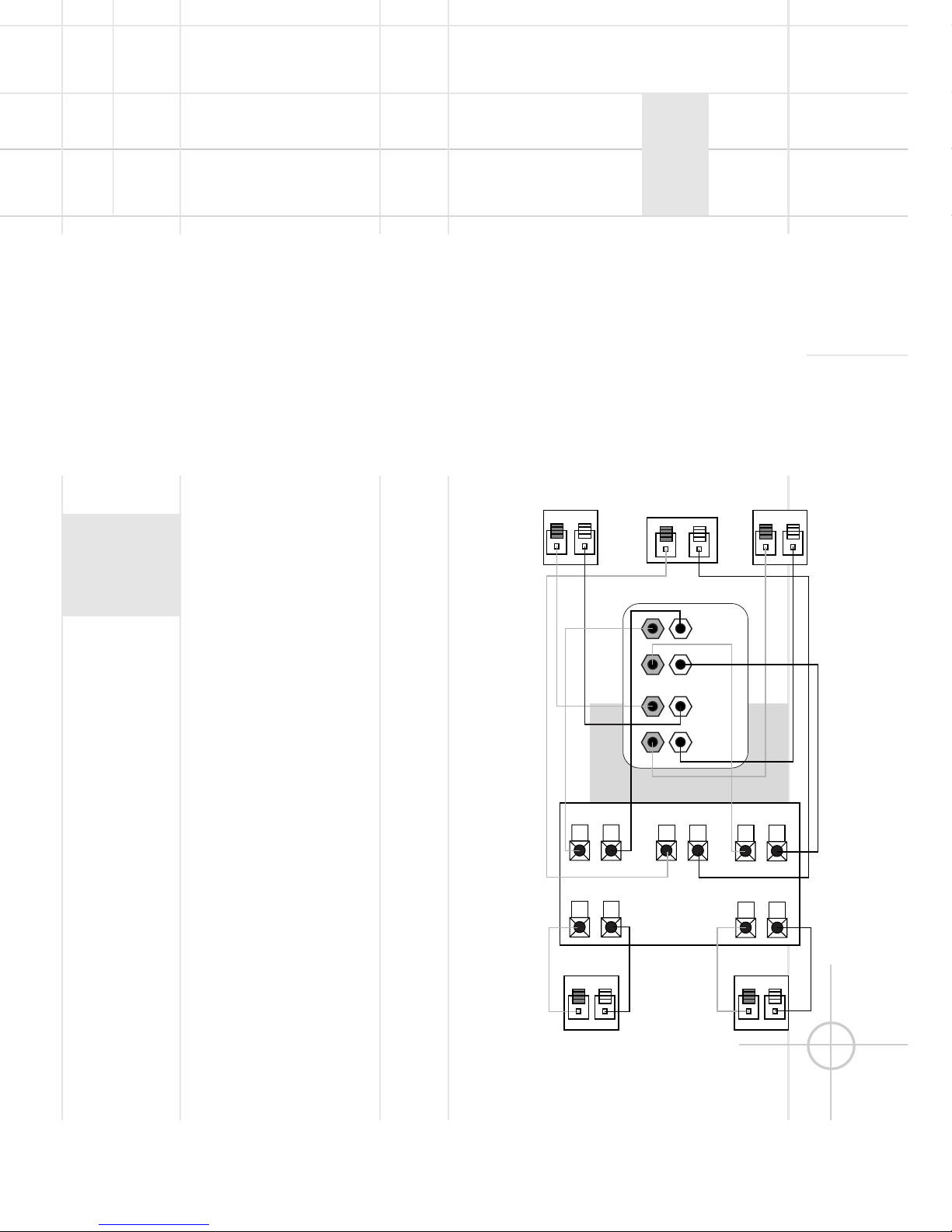
Dolby* Pro Logic* (Non-Digital) – Speaker Level
Use this installation method
for Dolby Pro Logic appli-
cations (not Dolby Digital,
DTS®or other digital
processing), where the
receiver/processor does not
have a subwoofer output or
a volume-controlled preamp
(line-) level output:
Connect your receiver or
amplifier’s front left and right
speaker terminals to the left
and right terminals on the
subwoofer that are marked
“High Level In.” Connect the
left and right terminals on the
subwoofer that are marked
“High Level Out” to the cor-
responding terminals on the
back of your front left and
right speakers.
Connect your receiver or
amplifier’s center, left and
right surround-speaker
terminals to the corre-
sponding terminals on the
back of your center, left and
right surround speakers.
SPEAKER CONNECTION