jcb 1.25QE User manual

JCB POWER PACK
1.25QE –1.50QE
Quick Start Guide

> This Quick Reference Guide is to provide quick and simple information to the
Operator and does not include any health and safety aspects. In addition, because of our
continual development of machines, features described in this Quick Reference Guide
may differ from those on your machine. No errors and emissions be entirely ruled out.
> This Quick Reference Guide DOES NOT replace the Operators Manual. You MUST
read ALL the disclaimers and safety and other instructions in the Operators Manual
before initially operating this product. Accordingly, no legal claims can be entertained on
the basis of the data, illustrations or descriptions in this Quick Reference Guide.
This machine should not be operated by any person who isn’t appropriately qualified or
had the appropriate training.
Operation of this machine without periodic maintenance could cause it to malfunction.
For more information please contact your JCB Dealer.
DISCLAIMER
2
Please consult your manual for full information or consult your local dealer

INDEX
Disclaimer
Dimensions & Volumes
Key Components
General Checks
Start Up Instructions
Control Panel Overview
Lifting
Positioning
Stacking
Emergency Stops
FAQ
3
Please consult your manual for full information or consult your local dealer
2
4
5
8
9
10
11
12
13
14
15

DIMENSIONS & VOLUMES
4
Please consult your manual for full information or consult your local dealer
MODEL 1.25QE 1.50QE
Single Phase Output –V230 230
Total Storage Capacity - kWhr 23 46
Maximum Recommended Depth Of
Discharge - % 90 90
Capacity To 90% Depth Of Discharge - kWhr 20 41
Continuous Output At 25˚C -kW 8 8
Length 1000 1000
Width 1000 1000
Height 1000 1000
Weight 530 665

KEY COMPONENTS
5
Please consult your manual for full information or consult your local dealer
Front View
Side View
A Lifting Points (x4)
B Tie down points (x4)
C Fork pockets
D Ventilation grilles
E Control
F Connections
Isometric view for clarity
A
B
F
C
E
C
CC
D

KEY COMPONENTS - CONTROLS
6
Please consult your manual for full information or consult your local dealer
A Control Screen
BMCB
C ON / OFF Buttons
D Emergency Stop
E Generator Autostart Terminals
AB
C D E

KEY COMPONENTS - CONNECTIONS
7
Please consult your manual for full information or consult your local dealer
F 16A Maintenance Charge Connection
G32A Power Out
H63A Charge Connection
J 63A Power Out
JH
F G

GENERAL CHECKS
After correct installation of the unit, the power pack must be fully checked
over before first starting can be attempted. Points to check include:
• A visual inspection for signs of damage.
• Ensure all ventilation grilles are unobstructed (300mm free air
recommendation).
• Check the load cables to ensure all connections are firmly installed in the
correct position, and that wires are in good condition.
• Ensure the power pack is located on flat level ground.
• Ensure the power pack is located to prevent sitting in standing water.
• Ensure that the power pack is located so as to avoid impact damage
8
Please consult your manual for full information or consult your local dealer
Before Use
IMPORTANT
If you are using a generator to recharge your JCB Power Pack then it is essential that the
generator is correctly sized. This should be either a dedicated single phase generator, or a 3
phase generator that is suitably sized to prevent an excessive phase imbalance.

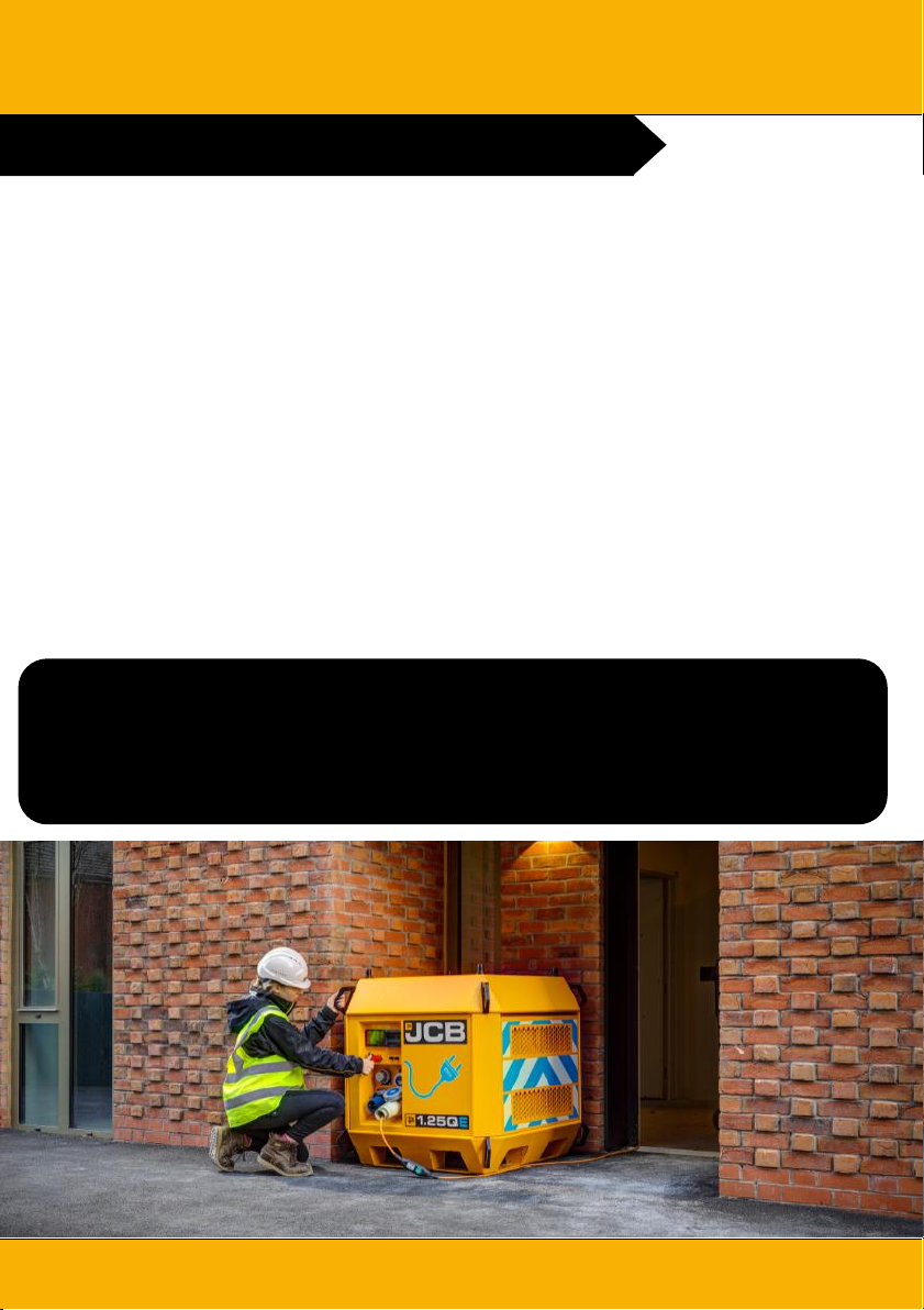
START UP INSTRUCTIONS
9
Please consult your manual for full information or consult your local dealer
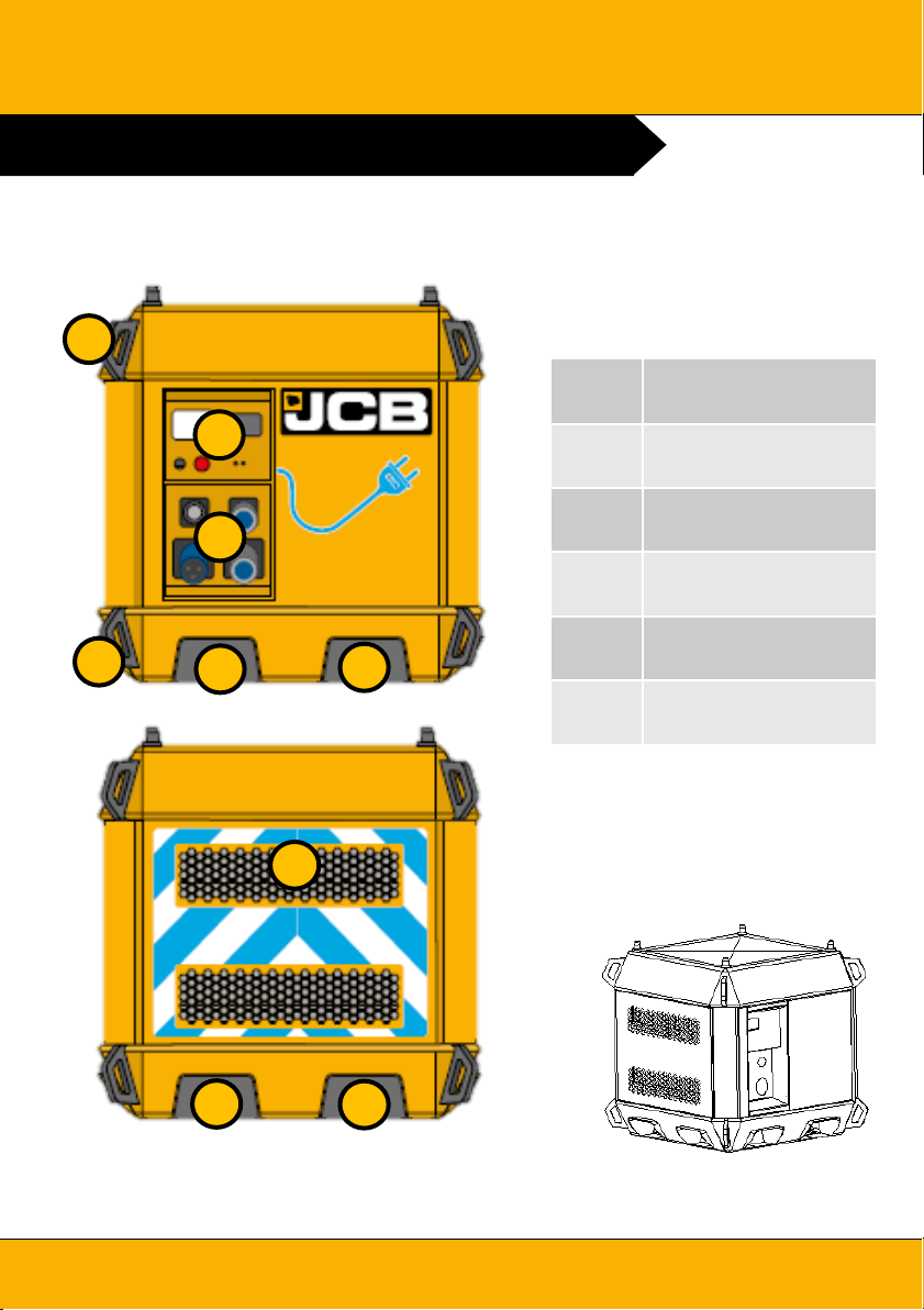
1. Ensure MCB (B) are in the
ON position.
2. Press and hold the Green
START button (C) for 10-20
seconds until the start relay
engages.
3. Control panel (A) will start its
initialisation (c20 seconds).
4. Once active the control panel
display will indicate current
status.
5. Unit is now connected to load.
NOTE: Generator autostart
terminals (E) will energise if site
load exceeds 8kW (de-energise
once it drops back below 6kW)
or if the battery level drops
below 5% (de-energise above
95%)
IMPORTANT
Pressing the red OFF button
(F) will isolate the batteries but
will still allow passthru from the
AC input to the load.
The Emergency stop (D) will
isolate the output connections
from all sources
AB
C D E
F

CONTROL OVERVIEW
10
Please consult your manual for full information or consult your local dealer
A Input Supply
B
Inverter Status (detail
below)
AC Input AC Output
A C
D
Inverting
Bulk
Passthru
Off
No AC input,
batteries only
Batteries are
charging, no load
AC connected to load
and charging batteries
Unit is OFF
B
C Output Supply
D Battery Status

LIFTING
The power pack should only be lifted using the designated lifting points or the fork
pockets where provided.
For movement on site the fork pockets enable the power pack to be lifted and shifted by
forklift or telescopic handler. The fork pockets are sized and spaced to allow lifting by
equipment with a stand fork carriage.
11
Please consult your manual for full information or consult your local dealer
NOTE: Always ensure that lifting equipment is rated to lift the load.
Weights are shown on the power pack rating plate. While both the fork
pockets and lifting frame are rated to allow lifting, the operator needs to
ensure that they have adequate lifting capacity.
A Lifting Points (x4)
B Fork Pockets
C Lifting Decal
D Tie Down Points (x4)
C
B
A
D

POSITIONING
12
Please consult your manual for full information or consult your local dealer
Your JCB power pack has a rugged
design and is suited for life on a hard
working site, however there are
precautions that should be undertaken
to ensure a long service life
•Units should be located on flat level
ground
•If the machine is sat in standing/rising
water then if the level reaches
200mm the performance of the
machine may be compromised.
Where possible position the machine
on higher ground.
•Units should be positioned to
minimise the risk of impact damage

STACKING
13
Please consult your manual for full information or consult your local dealer
The JCB power pack is designed to be stackable up to 2 units in use or 3 units in
storage. Model 1.25QE and 1.50QE are interchangeable.
NOTE: When stacking
equipment always
ensure that the roof
mounted securing pegs
are engaged with the
sleeves on the underside
of the unit being stacked
IMPORTANT
Stacked units MUST be sited on
flat, level, stable ground

EMERGENCY STOP
A machine isolation button/emergency stop button is mounted externally on the
canopy If pressed, all machine systems will stop completely.
Use the emergency stop button in the case of an emergency.
Under normal operation the power pack should be turned off using the STOP button.
This can be clarified in the Control Panel section of your Operators Manual.
The emergency stop button is a twist to release type and will need a ¼ turn clockwise
to disengage.
14
Please consult your manual for full information or consult your local dealer
IMPORTANT
Pressing the red OFF button will isolate the batteries but will still allow
passthru from the AC input to the load.
The Emergency Stop will isolate the output connections from all sources

FAQ
15
Please consult your manual for full information or consult your local dealer
1. Is the Power Pack suitable for 3 phase loads?
2. How long will it run for?
3. How long does it take to recharge?
4. How much power does it have?
5. What can I use to recharge my Power Pack?
Power Pack models 1.25QE and 1.50QE are only capable of a single phase,
230V, 50Hz output.
This will depend on the load that is applied. 1.25QE has 21kWhr of useable
capacity while the 1.50QE has 41kWhr of useable capacity. Put simply, a 2kW
load would drain the batteries in either 10 or 20 hours depending on you
Power Pack model. If you apply more load it will drain faster, less load and it will
drain slower.
The inverter output is rated at 8kW @ 230V single phase.
Your Power Pack can be recharged via either the main 63A input or by the 16A
trickle charge connection. Any single phase, 230V, 50Hz supply connected to
these input connections will allow the Power Pack to recharge
This will vary depending on several factors including battery levels, ambient
temperatures and the size of supply you have available. Based on a 32A input
and a full recharge from 10-100%, the typical recharge time would be 3 hours
for 1.25QE or 6 hours for 1.50QE

FAQ
16
Please consult your manual for full information or consult your local dealer
6. Will the Power Pack automatically start my site generator?
7. Why is my generator ‘hunting’ when connected to my Power Pack?
8. What maintenance does it need?
9. Can I add solar panels to my Power Pack?
10. How much noise does it make?
Your Power Pack has 2 volt free contacts mounted on the control section (see
page 6). These will be activated if the site load exceeds 8kW or if the battery
capacity falls to 5%.
You should check that your generator is correctly sized. The JCB Power Pack
will draw up to 7kW of single phase power when recharging. Your generator
should be rate to supply this load without unduly loading a single phase.
A solar input is an optional feature on the JCB Power Pack. Please contact your
supplying dealer for confirmation of individual model specifications.
There may be a little bit of fan noise, but to all intents and purposes, the system
is silent in operation
Apart from periodic inspections the Power Pack is maintenance free. The only
checks that you will need to make is that the unit has charge.

All rights reserved. No part of this publication may be reproduced, stored in a retrieval system, or transmitted in any
form or by any other means, electronic, mechanical, photocopying or otherwise, without prior permission from J C B
Sales. All references in this publication to operating weights, sizes, capacities and other performance measurements are
provided for guidance only and may vary dependant upon the exact specification of the machine. They should not
therefore be relied upon in relation to suitability for a particular application. Guidance and advice should always be
sought from your J C B Dealer’. J C B reserves the right to change specifications without notice. Illustrations and
specifications shown may include optional equipment and accessories.
J C B Sales Limited, Rocester, Staffordshire, United Kingdom ST14
5JP Tel: +44 1889 590312 Email: salesinfo@jcb.com
Download the very latest information on this product range at: www.jcb.com
The J C B logo is a registered trademark of J C Bamford Excavators Ltd. ©2009 J C B Sales. 17
Please consult your manual for full information or consult your local dealer
Image Location: Master
G125RS 1
This manual suits for next models
1
Table of contents