JDM DA-2501P User manual

JD-MEDIA
DIGITAL POWER AMPLIFIER
DA-2501/2502/2504/5001/5002/1000
DA-2501P/2502P/5001P/5002P/1000P

AUTION AVIS
FEATURES
SAFETY INSTRUCTIONS
C
RONT PANEL CONTROLS
EAR PANEL CONTROLS
F
R
O
1
1
1
2
2~4
6
NSTALLATION (설치)
I
5
LOCK DIAGRAM
8
B
PECIFICATIONS
S
9
UTPUT CONNECTIONS
F
7
AULT DETECTION MODULE (FD-200)
1. 제품보관방법(
How to keep in product)
가능한 습도가 없는곳에 보관하고 보관추천온도는 영하15도부터 영상 30도이하가 적합 합니다.
avoid in humidity place.keep in dry if possible, recommand temperature at the range -15 to +30
2. 운송방법(
How to forward goods)
배,또는 트럭으로 운송하되 운송시 컨테이너나 파렛트포장을 추천합니다.
recommand shipping by sea or truck with container or pallette packing
3. 제품 폐기및 재활용(
disassembling and re-cycling)
4. 제품의 생산이력및 정보 (serial number information of product made)
제품폐기시 재활용가능품목(철판,구리,기타 금속물등)을선별 하여 분리후 폐기 하십시오.
disassembling product after use,re-cycle steel and cooper and materials
ex)
2017 Year
2020 : A , 2021 : B , 2022 : C...
Model Name
7 XXXXXX 0 2 8 - 07
Lot Number
Month
Made in Korea
5. 제품수명주기 (Life Cycle)
사용상의 환경에 따라 다르지만 보통 7~10년 주기로 제품을 교체하여 주시기 바랍니다.
Life Cycle is about 7~10 years, but it depends on environment.
“이 기기는 업무용 환경에서 사용할 목적으로 적합성평가를 받은 기기로서 가정용 환경에서 사용하는
경우 전파간섭의 우려가 있습니다.”

SAFETY INSTRUCTIONS
Read all safety instruction before operating the DPL Series amplifiers.
1. Install equipment as follow conditions.
The apparatus shall not be exposed to dripping or splashing and
no object filled with liquids, Such as vases, Shall be place on the
apparatus.
Install at the place, Not bending curved.
Do not install this apparatus in a confined space such as a book
case or similar unit.
Locate power amplifier away from heat source, Such as radiators
or other device that produce heat.
Do not drop objects or spill liquids into the inside of amplifier.
2. Keep in mind the following when connecting amplifier.
Connect the amplifier after reading of O/P manuals.
Connect each connection of amplifier perfectly, If not, It maybe
Caused hum, Damage, Electric shock in case of mis-connecting.
DC high voltage in the amplifier may be caused dangerous,
do not open top cover.
Connect the power cord with safety after check of AC power.
Amplifiers should be serviced by qualified service person.
안 전 사 항
제품을 운용하기전에 모든 안전사항을 읽어 보십시오.
1. 이런 장소에 설치하여 주십시오.
진동이나 경사가 심하지 않고 바닥이 평평한 장소.
통풍이 잘되고 물기나 습기가 많지 않은 장소.
직사광선을 받지 않는 장소 또는 난방기구(발열체)에서 멀리 떨어진 장소.
인화성 물질(화학약품)이 없는 장소.
2. 설치시 이런점을 주의하십시오.
사용설명서 시스템 연결방법을 완전히 읽으신 후에 연결해 주십시오.
각종 연결선을 완전하게 연결해 주십시오.
(주전원 코드를 뽑은 상태에서 연결.)
불완전한 연결은 잡음, 제품의 손상 또는 안전사고의 원인이 됩니다.
내부에 DC 300V이상의 고압 통전부가 있어 전기적 충격 또는 감전사고의 위험이
있으므로 뚜껑을 열지 말아주십시오.
주 교류 전원 플러그를 연결하기 전에 사용전압을 확인하신 후 안전하게
연결하십시오.
제품을 수리시는 규정된 부품과 자격이 있는 사람이 수리를 하여야 함.
1
FEATURES
특징
1. High efficificate of PWM amplifier
2. AC power is faulty , amplifier is supplied DC24V automatically.
3. PFC (POWER FACTOR CORRECTION) for high efficiency of amplifier.
4. Increasing DC24V stand-by mode time to reduce DC stand-by power
consumption.
5. Remove 100V OUTPUT TRANSFORMER to reduce weight and
increase amplifier efficiency.
6. Full Protection circuit (OVER LOAD , OUTPUT SHORT , IN-RUSH
CURRENT and OTP)
7. Low noise variable speed cooling fan to increase amplifier reliability
8. PGM and PRI INPUT , PRI input have priority function. If Signal is
input to PRI , PGM signal is cut automatically.
9. Use with FD-200 module to detect amplifier operating fault.
이 기계(장치)는 물에 접촉(물에 적시는 정도의 접촉)해서는 않되며
꽃병과 같은 액체가 담겨진 물체를 기계 가까이 두는것을 금지 하여야
합니다.
Don't contact unit and water , in order to don't put liquid as like
water near by main unit.
1. P.A 시스템에 합리적인 PWM 방식의 D-급 앰프로서 소형, 경량, 고효율을 실현
하였습니다.
2. 고효율, 경량화의 DUAL SMPS 전원 방식을 채택하여 비상시 자동으로 DC24V전원
으로 전환됩니다.
3. 고역률 및 고효율화를 목적으로 AC전원의 역률보정회로를 적용하였습니다.
4. DC 전원의 대기전력을 획기적으로 줄여 비상전원의 대기능력을 향상시켰습니다.
5. OUT TRANSFORMER를 사용하지 않는 100V라인 출력구조로 되어 있어 무게가
가볍고 효율이 높습니다.
6. OVER LOAD, OUT SHORT, SOFT START, OTP등 완벽한 프로텍터를 탑재 하여
각종 위험요소로부터 앰프를 보호합니다.
7. 온도에 반응하여 회전속도가 조절되는 쿨링 회로를 적용하여 저소음을 실현하고
과열로부터 효과적인 냉각이 가능하며 앰프의 신뢰성을 높였습니다.
8. 2개의 INPUT(PGM INPUT와 PRIORITY INPUT)을 구성하여 우선신호 입력시 자동
으로 전환되는 입력구조로 제품의 응용 다양성을 갖추었습니다
9. 당사의 FD-200 모듈을 적용 할 수 있는 되어있어 해당모듈을 장착하면 앰프의
상태를 실시간으로 체크하여 고장여부를 모니터할 수 있습니다

1. PROTECT
OVER LOAD, OUTPUT SHORT, SOFT START, OTP등의 보호회로
작동시 PROTECT 램프가 점등됩니다
1. 교류 전원 소켓
교류전원 공급용 소켓이며, 후면의 주전원 스위치가 "OFF" 된 상태
에서 전원 코드를 끼워 주십시오
2. 전원 스위치
전원 스위치로서 [ I ]자 표시부분을 위로 누르면 전원이 공급되며
POWER LED가 켜집니다.
3. 베터리 전원(+24V) 입력단자
교류전원 정전되었을 때 직류 24V베터리로 부터 전원을 공급받는
직류 전원 입력단자입니다.
앰프의 출력 신호가 CLIP 상태에 이르게 되면 본 CLIP 램프가 점등
됩니다. CLIP램프가 점등 되지않는 범위 내에서 사용 하십시오.
2. CLIP
앰프가 음성신호를 출력하고 있음을 표시합니다.
3. SIGNAL
전원스위치가 ON 되어 앰프에 전원이 투입되어 있음을 표시합니다.
4. POWER
1. PROTECT LED
SOFT START, OVER TEMP, OUTPUT SHORT protection circuit is
operated, the LED is turned on.
2. CLIP LED
Amplifier output level is cliping , the LED is turned on.
Please use amplifier within CLIP LEVEL.
3. SIGNAL LED
Amplifier output is operated , the LED is turned on.
4. POWER LED
Amplifier is supplied AC or DC power by power switch ,
the LED is turned on.
F
2
1 2 3 4
DA-2504
Power Amplifier
SignalSignal ClipClip ProtectProtect
SignalSignal ClipClip ProtectProtect
AMP-1
Power
AMP-2
AMP-3 AMP-4
1
2
4 64
REAR PANEL CONTROLS (후면기능)
3 5 7 8 9
1011 12
POWER
DC POWER
24V/40A
220-240V~ , 50/60Hz
1200W
AC FUSE
T10AL 250V
FD-200
Fault Detector
(option)
FD-200
Fault Detector
(option)
COM 100V
)(20
COM 100V
)(20
AMP-2 AMP-1
POWER AMPLIFIER
MODEL : DA-5002P
AMP-1
AMP-2
0
Level
10
G
0
Level
10
0
ON
OFF
Level
10
0
Level
10
G
G
G
PRIORITY
INPUT
PGM
INPUT
200Hz
FD-200
200Hz
PRI
CTL
PRI
CTL
Fuse Rating
T40AL 32V
BALANCED OUTPUTS
RMS 500W
FD-200
ON
OFF
Off:Fault
On:Normal
FD-200
중요사항 : DC 전원연결시 +측과 -측의 단자를 사용하여 연결시
(-) 전원단자를 연결후 (+) 전원단자를 연결하십시오. 연결시
전원극성이 잘못 연결되면 제품에 결함이 발생할수 있으니 주의
바랍니다. 베터리 연결케이블은 직경이 5.0mm 이상 길이 4m
이내로 사용하십시오.
3. DC POWER TERMINALS
This is terminals for DC24V battery power supply, when unexpected
AC power failure.
IMPORTANT: Be sure to link +, - for DC power, please note the
(+)(-) polarity. When connecting DC 24V terminal in case of using
emergency power source for unexpected AC power failure. For the
use the cable length within 4m/5.0mm diameter.
1. AC POWER INLET
This is AC power inlet, please connect power plug after main power
switch “OFF”
2. POWER SWITCH
This power switch , push [ l ]part of power switch , AC power is
supplied and turn on LED indicator.
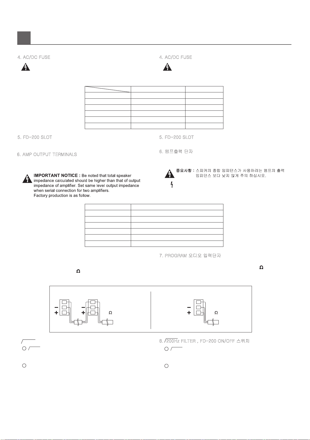
중요사항 : 휴즈를 교체시에는 반드시 규정된 정격 휴즈를
자격이 있는 사람이 휴즈를 교체 하십시오.
4. AC/DC FUSE
3
MODEL
DA-2501P
DA-2502P
T2AL 250V
T3.15AL 250V
T15AL 32V
T20AL 32V
DA-2504 T6.3AL 250V T40AL 32V
DA-5001P T3.15AL 250V T20AL 32V
DA-5002P T6.3AL 250V T40AL 32V
DA-1000P T6.3AL 250V T40AL 32V
VOLTAGE AC220V, 230V, 240V ~ DC 24V
MODEL
DA-2501P
DA-2502P
100V / 40Ω
100V / 40Ω
DA-2504 100V / 40Ω
DA-5001P 100V / 20Ω
DA-5002P 100V / 20Ω
DA-1000P 100V / 10Ω
IMPEDANCE
IMPORTANT : When fuse is blown out, it should be replaced with
same type just like following table, if it continues to blown out,
stop replacing fuse and
refer servicing to qualified
person.
4. AC/DC FUSE
REAR PANEL CONTROLS (후면기능)
FAULT DETECTOR MODULE(FD-200)을 장착하기 위한 슬롯입니다.
5. FD-200 SLOT
스피커와 임피던스 매칭을 쉽게 하기위해 100V 출력으로 설계되어
있습니다
6. 앰프출력 단자
: 본단자에 접촉시 전기적 충격이 있을수 있습니다. 기기의 결선등 으로
부득이 접촉 해야할 경우 반드시 기기의 전원을 끄고 작업 하십시오.
PROGRAM 오디오 신호(일반방송)를 위한 입력단자로서 스크류 터미널로
설계되어 있습니다. 정상입력 레벨은 0dBu(0.775V) 30K 바란스 형태입
니다. 동일한 입력신호를 앰프에 병렬로 공급할 경우는 아래 그림과 같이
링크하여 사용하십시오.
7. PROGRAM 오디오 입력단자
7. PROGRAM AUDIO INPUT TERMINALS
Audio input terminal of PROGRAM signal(for normal announcement) with
screw terminal.
Input level is 0dBu (0.775V) 30K balanced.
Please make external wire link as below in case of using amplifier in serial
connection.
This makes reduction of resonance sound inside to make a clear
sound when pushing H.P.F
Set the switch FD-200 for use of FD-200.
Be sure to set switch Normal, not using FD-200.
Setting of switch is Normal position, When factory production.
8. 200Hz FILTER , FD-200 ON/OFF 스위치
이 스위치를 "ON" 위치로 설정하면 200Hz H.P.F를 통과하여
실내 공진음을 감소시켜 음질의 명료도를 향상시킬수 있습니다.
기능을 사용하고자 할때 이 스위치를 FD-200 위치로 하십시오.
단 FD-200 기능을 사용하지 않을때는 반드시 이 스위치를
Normal위치로 설정하십시오.
공장 출하시 이 스위치는 Normal 위치로 설정 되어 있습니다.
FAULT DETECTOR MODULE (FD-200)을 장착하여 FD-200
. 200Hz ON/OFF (H.P.F)
1
. FD-200 ON/OFF 스위치
2
8. 200Hz FILTER , FD-200 ON/OFF SWITCH
. 200Hz ON/OFF
SWITCH (HPF)
1
. FD-200 ON/OFF SWITCH
2
GG
PGM INPUT
AMP-1AMP-2
0dBu(0.775V)
PGM
AUDIO INPUT
30K BAL
LINK
G
PGM INPUT
AMP-1
1-CHANNEL2-CHANNEL
0dBu(0.775V)
PGM
AUDIO INPUT
30K BAL
5. FD-200 SLOT
This is slot for installation of FD-200 (Fault Detector Module)
Amplifier is designed to 100V output to simple matching for speaker and
impedance.
6. AMP OUTPUT TERMINALS

GPRI
CTL
4
REAR PANEL CONTROLS (후면기능)
Audio input terminal of PRIORITY signal (for E/M announcement and
REMOTE announcement)with screw terminal.
Input level is 0dBu (0.775V) 30K balanced.
9. PRIORITY AUDIO INPUT TERMINALS
정상 입력 레벨은 0dBu(0.775V) 30K 바란스 형태입니다.
PRIORITY 오디오 신호(비상방송 또는 원격방송)를 위한 입력단자
로서 스크류 터미널로 설계되어 있습니다.
동일한 입력 신호를 앰프에 병렬로 공급할 경우는 아래 그림과 같이
링크 하여 사용하십시오.
9. PRIORITY 오디오 입력단자.
PRIORITY 오디오 입력싱호에 대한 앰프의 출력레벨을 조절하는
음량조절기 로서 시계방향으로 돌리면 출력레벨이 증가 합니다.
10. PRIORITY 레벨 볼륨
Please make external wire link as below in case of using amplifier in serial
connection.
GG
PRI INPUT
AMP-1AMP-2
0dBu(0.775V)
PRIORITY
AUDIO INPUT
30K BAL
LINK
G
PRI INPUT
AMP-1
1-CHANNEL2-CHANNEL
0dBu(0.775V)
PRIORITY
AUDIO INPUT
30K BAL
It can be adjust volume for Priority input signal, the adjustment
is turned right by screwdriver, priority input signal is increased.
10. PRIORITY LEVEL ADJUSTMENT
1
For switch or relay contact
1
Connect terminal of AMP PRIORITY CONTROL OUT of RG-3220.
When control PRIORITY by external switch contact or external relay
contact, Refer to the as below.
. RG-3220과 사용시
당사 모델 RG-3220의 AMP PRIORITY CONTROL OUT 단자와 연결
하여 사용할 경우 사용법입니다.
2
For RG- 3220
2
. 스위치 또는 릴레이 접점단자 사용시
This is Priority Control input terminal and You use that like
under below.
PRIORITY CONTROL 신호를 스위치 접점이나 RELAY 접점을 사용
하여 콘트롤 하고자 할때 사용합니다.
12. PRIORITY CONTROL 입력단자
12. PRIORITY CONTROL INPUT TERMINALS
PRIORITY CONTROL 입력단자로서 다음과 같이 2가지 방법으로 사용
11. PROGRAM 레벨 볼륨
PROGRAM 입력신호에 대한 앰프의 출력레벨을 조절하는 음량조절기로서
시계방향으로 돌리면 출력 레벨이 증가합니다.
11. PROGRAM LEVEL ADJUSTMENT
It can be adjusted output level for PROGRAM input signal, the adjustment
is turned right , output level is increased.
하실수 있습니다.
+24V
PRIORITY CONTROL
SIGNAL
OR
PRIORITY CONTROL
SWITCH
RG-3220
AMP PRIORITY
CONTROL OUT
GPRI
CTL
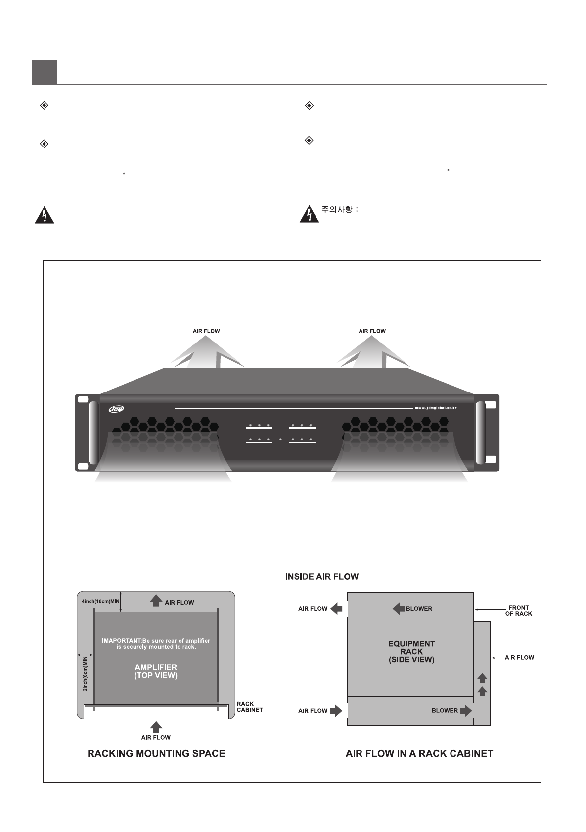
NSTALLATION (설치)
Amplifier racking size for PA series are designed for standard 19"
equipments are made frequency disturbances. Please keep
distance more than 1m for amplifier and mentioned unit
Never block the air vents front of the amplifier, The following
is figure of air-flow. Check inside temperature of rack system so as
COOLING
IMPORTANT NOTICE: Radio receiver , TV and other wireless
MOUNTING
not to be more than 40 C for the stable operating in any case, we
recommend you to install cooling fan additionally on the rear panel
of rack cabinet.
I
rack mounting. Please pay close attention to the cooling requirements.
표준 19" 랙에 장착할 수 있는 구조로 설계되어 있으며, 방열에 필요한
앰프의 전면에 있는 공기 구멍을 절대 막지 말아 주십시오.
앰프 냉각 구조의 공기 흐름은 아래 그림과 같은 형태입니다.
방열
주의사항 : 라디오 수신기 또는 TV 및 기타 무선기기와는 간섭이
있을수 있으니 가급적 1M이상의 거리를 두고 설치 하십시오.
랙조립
안정된 운용을 위해서는 랙 내부 온도가 40 C를 초과하지 않도록
신경을 쓸 필요가 있으며, 냉각 효과를 증가시키기 위해 랙 뒷벽에
송풍기를 부착하여 주십시요.
통풍 구조에 신경쓸 필요가 있습니다.
5
DA-2504
Power Amplifier
SignalSignal ClipClip ProtectProtect
SignalSignal ClipClip ProtectProtect
AMP-1
Power
AMP-2
AMP-3 AMP-4

INDEPENDENT SPK SYSTEM
It will be used for independent speaker zone system.
독립된 스피커 시스템
이 방법은 스피커 존이 독립된 시스템으로 운용할때
사용되는 방식입니다.
OUTPUT CONNECTIONS
For the serial connection, impedance setting between
matching transformer and output power of amplifier is
most important. Be sure that total primary impedance
calculated should be higher than that of output
impedance
of amplifier.
앰프 출력을 직렬 연결시는 앰프 출력과 매칭 트랜스의 임피
던스 설정이 대단히 중요하며, 어떠한 경우라도 연결하려는
매칭 트랜스의 합산된 1차 임피던스가 앰프의 출력 임피던스
보다 낮아서는 안됩니다.
6
Method of matching trans calculation
.
SPK Q'TY =
=
Series output amp wattage
SPK output wattage per piece
EX) In case SPK output power requirement is
SPK Q'TY =250W = 25 PCS
10W
100V = 1K
10W
AMP-1
100V 100V
100V
COM
100V
COM
AMP-2
2
AMP RATED IMP = 100V = 40
250W
2
MATCHING TRANS
FIRST STEP IMP =
MATCHING TRANS
FIRST STEP IMP
SPK output wattage per piece
AMP output voltage 2
AMP RATED IMP =
AMP rated power
AMP output voltage
2

제품의 설명
DESCRIPTION
설치
1. 앰프의 파워 코드를 AC OUTLET 으로부터 뽑으십시오.
파워 앰프의 fault detection 모듈은 출력레벨 2V RMS(70 or 100V line)
에서 20KHz의 주파수에 의해서 앰프의 작동 상태를 파악하고, 스피커
라인의 접속 끊김을 체크합니다.
Block diagram에서 볼수 있듯이, 20KHz(2V RMS)는 스피커 케이블을 통
해서 detection 모듈로 전달이 되며 앰프의 출력상에서 다른 signal과 섞
이게 된다. 그리고 detection 모듈은 fault를 체크하는 filter를 통해서 20
KHz 주파수를 감시합니다.
2. FD-200 SLOT의 BLANK PANEL을 제거한 다음 콘넥터(AN601)가
묶인 케이블타이를 풀어주십시오.
3. FD-200 모듈의 CN601에 콘넥터(AN601)를 연결한 다음 FD-200
보드상의 SW1을 ON위치로 설정하십시오.
5. FD-200을 후면 판넬에 부착하십시오.
6. 앰프의 출력 터미널의 COM 단자와 100V 단자를 FD-200의 COM 단자
와 HOT 단자에 각각 결선하십시오.
7. FD-200의 릴레이 접점을 FS-3381(FAULT STAND-BY AMP SWITCHER)
1. Digital Portable Multimeter를 AC 전압 측정 레인지에 설정하고, 측정리
드를 파워 앰프의 COM과 100V 단자에 연결하시오.
"OSC LEVEL" 볼륨을 조정하여 전압계가 2Vac RMS(20KHz)가 되도록 설
정하십시오.
의 릴레이 접점 입력 단자와 결선하십시오.
파워 앰프의 PGM과 PRIORITY 입력 스크류 터미널을 뽑으십시오.
Ensure amplifier to be adjusted in not being used, I.e. Unplug
the PGM and PRIORITY input screw terminals.
INSTALLATION
1. Unplug the power cable from a AC outlet.
2. Remove the rear mounted blank panel, and mount the
FD-200 in the resultant hole using screws supplied with the module.
3.
of CN601 on the FD-200.
4. Set the switch "FD-200" of FD-200 ON/OFF switch on the
rear panel of amplifier.
5. Screw FD-200 on the panel.
7. Connect relay contact of FD-200 to the input terminal of relay
contact of FS-3381. (FAULT STAND-BY AMP SWITCH)
6. Connect "COM" of AMP output terminal and 100V terminal
to the "COM" and "HOT".
CALIBRATING FD-200 ON POWER AMPLIFIERS
파워 앰프 설치후 FD-200 조정방법.
4. 앰프의 후면 판넬의 FD-200 ON/OFF 스위치를 FD-200위치로 설정
하여 주십시오.
1. Set Digital Portable Multimeter to measure AC voltage and
Confirm output of power amplifier is 2Vac RMS at 20KHz.
Adjust "OSC LEVEL" potentiometer(VR602), If necessary.
주의: Digital portable multimeter는 20KHz 주파수를 측정할
수 있는 정밀한 계측기를 사용하십시오.
Note : Use accuracy Digital portable multimeter which has
FQ test range.
The fault detection module of power amplifier checks operating
conditions of amplifier and disconnection of speaker wiring by
giving out the sine wave of 20KHz at an output level of 2V RMS
(at 70 or 100V line).
As the block diagram shows, the sine wave of 20KHz(2V RMS)
deliverd to the detection module though speaker cables and
the detection module detects only the sine wave of 20KHz
through a filter to check a fault.
Set "ON" position SW1 on the FD-200 module after connection
connect across power amplifier COM and 100V terminals
is mixed with other signals on the amplifier output which is
FAULT DETECTION MODULE (FD-200)
7
Fault Detector OSC Level
Sensitivity
min max
FD-200 HOT
COM Sense
Line In
2. Sensivity 볼륨을 시계방향으로 천천히 Sens램프가 점등 될때까지
조정하십시오. Sens램프가 점등되는 시점에서 약 1~2˚ 정도 더
돌려 설정을 마무리 하시면 됩니다.
설정완료후 오디오를 출력하면 램프가 점멸 할수 있으나 에러는
아닙니다.
2. Adjusting sensitvity volume to turn on Sens LED. Turn on Sens
LED , adjust the volume to 1 ~ 2˚. Finish the setting and operating
amplifier, LED can be flicking, but it is not fault.
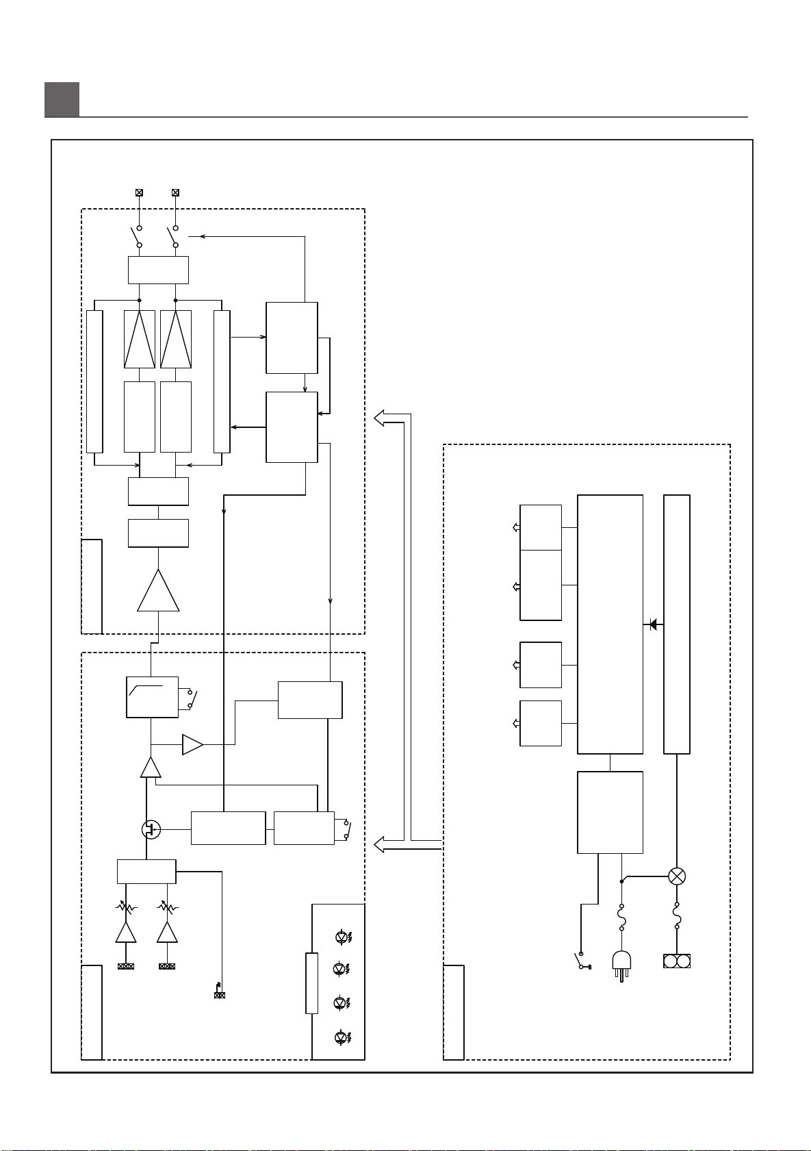
LOCK DIAGRAM (블럭도)
B
8
D-AMP
100V
cold
hot
Over cureent
Thermal
+
-
DC Power
24V
H.P.F
200Hz
AC Power
230V~,50Hz
Modulation
H/A
+/-80V
DC-OFF
P.W.M
Low pass Filter
PWM Mute
FEEDBACK
+15V
SMPS [AC/DC]
SMPS [DC/DC]
Pre amp section
+/-20V
+24V
Out stage power
on/off
Short detect
E.B
Program
Peiority E.B
hot
cold
com
hot
cold
com
EXCHANGE
GND
PRIORITY CON
SUM
FD-200 CARD
(OPTION)
on/off
MUTE CONTROL
PROT
Power SW
AMP FAULT
PROT
SIG, CLIP
INPUT BOARD AMP BOARD
POWER BOARD
D-AMP
Modulation
P.W.M
FEEDBACK
PHASE
CONVERTER
LOW PASS
FILTER
CLIP
SIG
POWER
DISPLAY B/D
PFC
(DC370V)
NOTE
1CH, POWER B/D: 1ea = AMP B/D: 1B/D 1CH
2CH, POWER B/D: 1ea = AMP B/D: 1B/D 2CH
4CH, POWER B/D: 1ea = AMP B/D: 1B/D 2CH*2

PECIFICATIONS (규격및 성능)
S
NOTE
Specifications and design subject to change without notice for improvements.
(내용상의 규격 및 특징은 제품의 성능 향상을 위하여 사전 예고 없이 변결될 수 있습니다.)
DC Power is designd to use only 8/1 output power, so DC power could not cover RMS output power.
(DC전원은 음성출력을 기준으로 설계 되었으므로 RMS출력을 보장하지 않습니다.)
9
LESS THAN 1%(1㎑)
More than 100dB("A"WEIGHT)
TECHNICAL
RATED OUTPUT
FREQUENCY RESPONSE
SIGNAL TO NOISE RATIO
T.H.D
DIMENSIONS(mm)
WEIGHT(kg)
50Hz ~ 18KHz (±3db)
50Hz ~ 16KHz (±3db)(DA-1000P)
DA-2501P: 250W(1kHz)
DA-2502P: 250W(1kHz) x 2CH
DA-2504: 250W(1kHz) x 4CH
DA-5001P: 500W(1kHz)
DA-5002P: 500W(1kHz) x 2CH
DA-1000P: 1000W(1kHz)
DA-2501P: 100V / 40Ω
DA-2502P: 100V / 40Ω
DA-2504: 100V / 40Ω
DA-5001P: 100V / 20Ω
DA-5002P: 100V / 20Ω
DA-1000P: 100V / 10Ω
OUTPUT IMPEDANCE
0dBm(0.775V)/ 30㏀BALANCEDINPUT LEVEL
OVER LOAD, OUT SHORT, SOFT START, OTPPROTECTION
220-240V~, 50/60Hz DC 24VPOWER SOURCE
DA-2501P : 350W
DA-2502P : 600W
DA-2504 : 1120W
DA-5001P : 600W
DA-5002P : 1175W
DA-1000P : 1220W
DA-2501P : 483(W) x 375(D) x 44(H)
DA-2502P : 483(W) x 375(D) x 88(H)
DA-2504 : 483(W) x 375(D) x 88(H)
DA-5001P : 483(W) x 375(D) x 88(H)
DA-5002P : 483(W) x 375(D) x 88(H)
DA-1000P : 483(W) x 375(D) x 88(H)
DA-2501P :5.5kg
DA-2502P : 6.5kg
DA-2504 : 7.7 kg
DA-5001P : 6.3kg
DA-5002P : 6.6kg
DA-1000P : 6.4kg
POWER
CONSUMPTION
DA-2501P : NOT APPLY
DA-2502P : APPLY
DA-2504 : APPLY
DA-5001P : APPLY
DA-5002P : APPLY
DA-1000P : APPLY
POWER FACTOR CORRECTION
(P.F.C)

www.jdmglobal.co.kr 18633(445-935)
23, Eunhaengnamu-ro 170beon-gil,
Yanggam-myeon, Hwaseong-si, Gyeonggi-do
Tel : +82-31-366-6400
Fax : +82-31-366-6404
C/N : 4M10-DPL010-02
JD-MEDIA CO.,LTD.
This manual suits for next models
10
Table of contents
Other JDM Amplifier manuals


