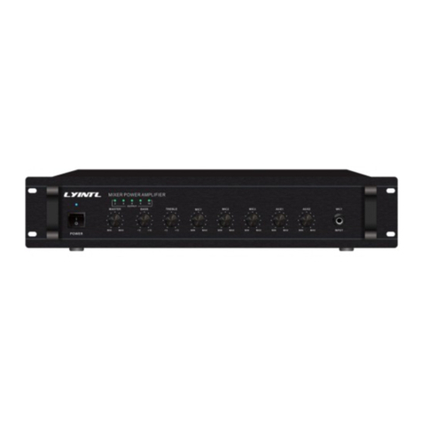
JDM MA-900A User manual

JD-MEDIA
SETREO POWER AMPLIFIER
MA-300A,600A,900A
- dB 0
3
6
9Clip Signal Power Power
PROTECTION Signal Clip
12
15
18
25
35
45
- dB 0
3
6
9
12
15
18
25
35
45 STEREO POWER AMPLIFIER
MA-900A
CHANNEL A CHANNEL B www.jd-media.co.kr
POWER

AUTION AVIS
FEATURES
SAFETY INSTRUCTIONS
RONT PANEL CONTROLS
EAR PANEL CONTROLS
NSTALLATIONS
ONNECTIONS
PECIFICATIONS
LOCK DIAGRAM
C
F
R
I
C
S
B
- dB 0
3
6
9Clip Signal Power Power
PROTECTION Signal Clip
12
15
18
25
35
45
- dB 0
3
6
9
12
15
18
25
35
45 STEREO POWER AMPLIFIER
MA-900A
CHANNEL A CHANNEL B www.jd-media.co.kr
POWER
- dB 0
3
6
9Clip Signal Power Power
PROTECTION Signal Clip
12
15
18
25
35
45
- dB 0
3
6
9
12
15
18
25
35
45 STEREO POWER AMPLIFIER
MA-600A
CHANNEL A CHANNEL B www.jd-media.co.kr
POWER
- dB 0
3
6
9Clip Signal Power Power
PROTECTION Signal Clip
12
15
18
25
35
45
- dB 0
3
6
9
12
15
18
25
35
45 STEREO POWER AMPLIFIER
MA-300A
CHANNEL A CHANNEL B www.jd-media.co.kr
POWER

1
SAFETY INSTRUCTIONS
Read all safety instruction before operating the MA-Series amplifiers.
1. Install equipment as follow conditions.
Install at flat place, not bending curved.
Do not install near the water and moisture.
Locate power amplifier away from heat source, such as radiators
or other device that produce heat.
Do not drop objects or spill liquids into the inside of amplifier.
2. Keep in mind the following when connecting amplifier.
Connect the amplifier after reading of O/P manuals.
Connect each connection of amplifier perfectly, if not, it maybe
caused hum, damage, electric shock in case of mis-connecting.
To prevent electric shock, do not open top cover.
Connect the power cord with safety after check of AC power.
Amplifiers should be serviced by qualified service person.
FEATURES
Automatic variable speed FAN.
Over heating portection.
Load short circuit protection.
㙼G㤸G㇠G䚡
㥐䖼㡸G㟨㟝䚌ὤ㤸㜄G⯜☔G㙼㤸㇠䚡㡸G㢱㛨G⸨㐡㐐㝘UG
XUG㢨⤤G㣙㋀㜄G㉘㾌䚌㜠G㨰㐡㐐㝘U
㫸┍㢨⇌G㇠ᴴG㐠䚌㫴G㙾ḔGⵈ␙㢨G䓽䓽䚐G㣙㋀U
䋩䗁㢨G㣌╌ḔGⱰὤ⇌G㏩ὤᴴG⬂㫴G㙾㡴G㣙㋀U
㫵㇠ṅ㉔㡸Gⵏ㫴G㙾⏈G㣙㋀G❄⏈G⇐ⵝὤẠOⵐ㜨㷨P㜄㉐G⫠G⛜㛨㫸G㣙㋀UG
㢬䞈㉥GⱰ㫼O䞈䚍㚱䖼P㢨G㛺⏈G㣙㋀U
YUG㉘㾌㐐G㢨⤤㥄㡸G㨰㢌䚌㐡㐐㝘U
㇠㟝㉘⮹㉐G㐐㏘䊐G㜤ⵝⷉ㡸G㝸㤸䢼G㢱㡰㐔G䟸㜄G㜤䚨G㨰㐡㐐㝘U
ᴵ㦹G㜤㉔㡸G㝸㤸䚌G㜤䚨G㨰㐡㐐㝘U
O㨰㤸㠄G䂈☐⪰Gゅ㡴Gㇵ䈐㜄㉐G㜤UP
⺼㝸㤸䚐G㜤㡴G㣕㢀SG㥐䖼㢌G㋄ㇵG❄⏈G㙼㤸㇠Ḕ㢌G㠄㢬㢨G╝⏼␘U
㤸ὤ㤵G㻝G❄⏈Gᵄ㤸㇠Ḕ㢌G㠸䜌㢨G㢼㡰⦐G⟐ 㡸G㜨㫴G⬄㙸㨰㐡㐐㝘UG
㨰GẄ⪌G㤸㠄G䙀⤠Ἤ⪰G㜤䚌ὤG㤸㜄G㇠㟝㤸㚉㡸G䞉㢬䚌㐔G䟸G㙼㤸䚌G
㜤䚌㐡㐐㝘U
㥐䖼㡸G㍌⫠㐐⏈Gἐ㥉═G⺴䖼ḰG㣄㢨G㢼⏈G㇠⣀㢨G㍌⫠⪰G䚌㜠㚰G䚜U
䏭GGGGGG㬉G
㝜⓸㜄G♤⢰G䑠G㋁⓸G㣄┍㦤㤼U
Ḱ㤸⪌G㥐䚐䟀⦐G⇨㣙U
Ḱ㜨G⸨䝬䟀⦐G⇨㣙U
㏘䙰䀘G㉔⦐G㌰䏬Gᶴ㻐䟀⦐G⇨㣙U
Over current protection.
Power delay on circuit (soft start)
Ultra low distortion circuit.
XLR, 1/4" Phone jack(LINK) input connector.
5-WAY binding post, speakon connector.
Selective stereo, bridged mono.
㤸㠄GḩἽG㫴㜤䟀⦐G⇨㣙U
syGⵃGXV[IG䔤㣡OspurP㢹⥙G䂌≙䉤G㵸䈑U
\T~hGⵈ㢬♝G䔠㏘䏬GⵃG㏘䙰䂌G㣡G㻐⥙UG
㸼㤴㞐㡜G䟀⦐⦐G㉘U
㚤䘸G㟨㟝㡴G㏘䊀⤼㝘SG⽀⫳㫴G⯜⊬⦐Gᴴ⏙U

1. LED INDICATOR
PROTECT LED
Protect LED light with the protection circuit activated:
1. After switching-on for approx. 3 seconds(in-rush delay)
.
(in-rush䟀⦐㣅┍)
1. LED
2. CHANNELVOLUME
PROTECT LED
XUG㤸㠄G㏘㠸㾌⪰G䁔G䟸GZ㸼┍㙼GslkᴴG䁐㫴G╝⏼␘U
YUG㏘䙰䀘G㻐⥙␜㜄G㫵⪌G㤸㚉㢨G㈑ὤ⮨G⸨䝬䟀⦐ᴴG㣅┍䚌⮤GslkᴴG䁐㫴
ZUG㚤䘸ᴴGḰ㜨㢨G╌⮨G⸨䝬䟀⦐ᴴG㣅┍䚌⮤GslkᴴG䁐㫴G╝⏼␘U
CLIP LED
SIGNALLED
POWER LED
㻐⥙G㐔䝬㜄G㢰Ἤ⤠㬄㢨Gⵐ㈑䚌⮨GslkᴴG䁐㫴G╝⏼␘U
㻐⥙G㐔䝬㢌G㡔ⱨ⪰G䖐㐐䚌㜠G㨰⏈Gslk㢹⏼␘U
㚤䘸㜄G㤸ὤᴴGḩἽ╌ḔG㢼㏨㡸G㚀⥘㨰⏈Gslk㢹⏼␘U
ᴵG㵸≄㢌G㢀⣽㡸G㦤㤼䚌⏈G⸰⪜㢹⏼␘U
3. POWER SWITCH
G㨰㢌
⽀⫳㫴G⯜⊬G㟨㟝㐐㜄⏈G㵸≄hG⸰⪜㡰⦐G㣅┍╌⮤G㵸≄Gi⸰⪜㡴GⵌG㐐ⵝ䛙
㡰⦐G─⥘G⋇ḔG㟨㟝䚌㐡㐐㝘U
ὤὤ㜄G㤸㠄㡸GGḩἽ䚌⏈G㏘㠸㾌G㢹⏼␘U
䁐㐡㐐㝘U
㥉⓸Gὤ␘⫤G䟸Gⵝ㜨䑄㢨G㐑㡰⮨G㤸㠄㡸G㨰㐐ὤGⵈ⣁⏼␘U
XUG㚤䘸㢌G㤸㠄㡸G䁘⚀⏈G㨰ⷴG㢀䛙ὤὤ☘㡸G⭰㤴G䁔G䟸㜄G㚤䘸㢌G㤸㠄㡸G
YUG㚤䘸㢌G㤸㠄㡸Gↀ⚀⏈G⸰⪜㡸Gⵌ㐐Gⵝ䛙㡰⦐G↑ᾀ㫴G─⫠ḔSGY¥Z⺸G
3. If the amplifier is overheated.
2. If a DC voltage is present at a speaker output.
╝⏼␘U
FRONT PANEL CONTROLS +ⳮጚត,
1
2
3
2
SIGNAL LED
SIGNAL LED light if the output signal exceeds 100mW.
POWER LED
POWER LED as operating light.
2. CANNEL VOLUME
Control for the output level of channel A,B.
3. POWER SWITCH
Provides power to the unit.
switched on.
2~3 minutes before switching off.
For the internal fans continue to cool the unit otherwise the
amplifier maybe damaged.
NOTE:
1. To avoid loud switching noises, always switch on the power
amplifier in an amplifier system after all other units have been
2. At first turn the volume fully counterclockwise. Then wait approx
CLIP LED light with overdrive.
CLIP LED
- dB
0
3
6
9Clip Signal Power Power
PROTECTION
Signal Clip
12
15
18
25
35
45
- dB
0
3
6
9
12
15
18
25
35
45 STEREO POWER AMPLIFIER
MA-900A
CHANNEL A CHANNEL B www.jd-media.co.kr
POWER

3. BALANCED XLR, PHONE INPUTS ZUG㢹⥙␜㣄
ᵄ㤸㢌G㠸䜌㢨G㢼㡰⏼G㏘䙰䀘G㉔G㣅㛹㡸G䚌ὤ㤸㜄Gⵌ☐㐐G
ὤὤ㢌G㤸㠄㡸G㨰㐐ὤGⵈ⣁⏼␘U
㏘䙰䀘G㉔㐐㜄⏈GἭ㉥㜄G㨰㢌G䚌㐡㐐㝘U
㏘䙰䀘G㉔㐐㜄⏈G㤸⥙G㋄㐘ḰG⑄䚅䑝䉤⪰G⋆㢨ὤG㠸䚌㜠
㻝⺸䢼Gẩ㡴G㉔㡸G㺐␜ᶤ⫠⦐G㉔G䚌㐡㐐㝘U
[UG㻐⥙␜㣄G
3
Normal input level is 1.6V (+4dBu) 15K balanced with channal
A,B XLR and 1/4" phone jack input terminal for the extension to
another amplifier connect link jack to another amplifier input jack.
ⵈ⢴㏘䝉G㢹⥙㣡㡰⦐㉐G㢹⥙Gᵄ⓸⏈GR[iOXU]}PGX\rGGGG㢹⏼␘U
4. SPEAKER CONNECTORS
Turn the amplifier off befor touching the output connection.
WARNING:
To prevent electric shock do not operate the amplifier with
any of the conductor portion of the speaker wire exposed.
SPEAKER CABLING:
Larger wire sizes and shorter lengths minimize both loss of
power and degradation of damping factor.
Do not place speaker cables next to input wirning.
5. MODE SELECTOR
BRIDGE MONO
STEREO
Both channels operate separately : for stereo or 2-channel
operation, speaker impedance for each channel at least 4 .
Both channels are connected as a bridge : for a speaker
impedance of at least 8 .
\UG㟨㟝⯜☐
㏘䊀⤼㝘
⽀⫳㫴G⯜⊬
㵸≄hRG䂌≙䉤⪰G㏘䙰䀘R␜㣄SG㵸≄iR䂌≙䉤⪰G㏘䙰䀘T␜㣄㝴GG
㜤䚌㜠G㻐⥙㡸G㫑ᵉ䚌ὤ㠸䚐Gⵝ㐑㡰⦐G㐔䝬G㢹⥙㡸G㵸≄h㜄⬀G
ᴵG㵸≄㢨G⺸⫠╌㛨G㟨㟝䚔G㟤㜄G㇠㟝╌⮤G㏘䙰䀘G㺐㋀G⺴䚌⏈
[GGGG㢹⏼␘U
ḩἽ䚝⏼␘UGG㏘䙰䀘G㺐㋀G⺴䚌⏈G_GGGG㢹⏼␘U
MODEL CONDITION AC 100V/120V AC 220/230/240V
MA-900A
MA-600A
MA-300A
T20AL 250V
T15AL 250V
T8AL 250V
T4AL 250V
T8AL 250V
T10AL 250V
Ch-B Ch-A
Ch-B
Ch-A/BRIDGED
Ch-B
Ch-B Ch-A
Ch-B /Ch-A BRIDGED
Ch-A
1
2
4 3
5
XUGẄ⪌G㤸㠄GḩἽ㟝G㋀䁇
Ẅ⪌㤸㠄GḩἽ㟝G㋀䁇㢨⮤SG㤸⮨㢌G㨰㤸㠄G㏘㠸㾌ᴴGIvmmI═Gㇵ䈐
㜄㉐G㤸㠄䂈☐⪰G↰㠀G㨰㐡㐐㝘U
YUGẄ⪌G㤸㠄G䡨㪼㟝G䝴⒈
Ẅ⪌㤸㠄㟝G䡨㪼G䝴⒈㢹⏼␘U
1. AC INLET SOCKET
This is AC power cord socket. Please connect the power cord after
main power switch "off".
2. AC FUSE HOLDER
This is AC fuse holder.
There is DC in P.C.B board
MODEL VOLTAGE 120VAC 220/230/240VAC
MOBILE35 120VAC
T6AL 250V(65TL)
T10AL 250V(65TL)
MOBILE60 T1AL 250V(S51)
T2AL 250V(S51) T500mAL 50V(50T)
T1A 250V(50T)
IMPORTANT NOTICE:
When fuse is blown out, it should be replaced with the same type
fuse like following table, if it continuous to blown out, stop replacing
fuse and refer servicing to qualified person.
㩅㟈㇠䚡GaG䡨㪼⪰GẄ㷨㐐㜄⏈Gⵌ☐㐐Gἐ㥉═G㥉G䡨㪼⪰G㣄
㢨G㢼⏈G㇠⣀㢨GẄ㷨䚌㐡㐐㝘U
REAR PANEL CONTROLS +㮮ጚត,#
STEREO POWER AMPLIFIER
JD-MEDIA CO., LTD.

4
th
th
INSTALLATION +☎㍂,
- dB 0
3
6
9Clip Signal Power Power
PROTECTION Signal Clip
12
15
18
25
35
45
- dB 0
3
6
9
12
15
18
25
35
45 STEREO POWER AMPLIFIER
MA-900A
CHANNEL A CHANNEL B www.jd-media.co.kr
POWER
CHANNE
CHANNE
CHANNE
LA
LA
L A
CHANNE
CHANNE
CHANNE
LB
LB
L B
jd
www jd
www.jd
di
-media
-media
k
co kr
.co.kr
POWER
POWER
POWER

Ch-B Ch-A
Ch-B
Ch-A/BRIDGED
Ch-B
Ch-B Ch-A
Ch-B /Ch-A BRIDGED
Ch-A
STEREO POWER AMPLIFIER
JD-MEDIA CO., LTD.
㐐㏘䊐G㜤Ἤ⫰㡴G㢰ⵌ㤵㢬G㉘㾌Gⵝⷉ㡰⦐G␘㢀㇠䚡㡸G㨰㢌G䚌㐡㐐㝘U
XUG㏘䙰䀘G⢰㢬G㜤㐐G㚤䘸㢌G㤸㠄G㏘㠸㾌⪰G㨰㐡㐐㝘U
YUG㏘䙰䀘G㉔㡴G㉔⓸⪰G㵬Ḕ䚌㜠G㨰㐡㐐㝘U
ZUG㚤䘸⏈GYᵐ㢌G⯜☐O㏘䊀⤼㝘SG⽀⫳㫴G⯜⊬P⦐G㤸䞌G㐐䇠G㍌G㢼㡰⮤SG
[UG㣌⯯═G㉔㡴G㏘䙰䀘㜄G㾌⮹㤵㢬G㋄ㇵ㡸G㸼⣌䚝⏼␘U
㚤䘸ᴴG┍㣅G㩅㢰⚀⏈G㤸䞌䚌㫴G⫼㐡㐐㝘U
㏘䊀⤼㝘Gⵝ㐑
㉔G䚌㐡㐐㝘U
⯜☐G㏘㠸㾌⪰G㏘䊀⤼㝘G㯱㡰⦐G㤸䞌䚌ḔG㏘䙰䀘GἭ㉥㜄G㨰㢌䚌㜠
Wiring the following instructions describe the most common
ways to install your amplifier into a sound system.
1. First, turn off power switch befor connection.
2. Refer to wirning diagram for speaker connection.
(stereo, bridge-mono)
3. MA-Series amplifier maybe operated in one of two modes
4. JD-MEDIA assumes no liability for damaged loads resulting from
careless amplifier use or deliberate over powering.
How to connect stereo(2-CHANNEL) mode
connect the output wiring as shown.
To put the amplifier into stereo mode, first turn the amplifier off,
then slide the stereo-mono switch toward the left, and properly
CONNECTIONS
PIN1
PIN1
PIN1
PIN1 CH-A
CH-B
5
METHOD 1
CH-A
CH-B
1
23
-
+
INPUT FROM
SOURCE
SHIELD
+
-
1
23SHIELD
+
INPUT FROM
SHIELD
+
BALANCED
UNBALANCED
Input Wiring Tips
SHIELD
SOURCE
METHOD 2
BRIDGE MONO STEREO
AUDIO
SIGNAL

BRIDGE MONO STEREO
AUDIO
SIGNAL
1
23
-
+
INPUT FROM
SOURCE
SHIELD
+
-
1
23SHIELD
+
INPUT FROM
SHIELD
+
BALANCED
UNBALANCED
Input Wiring Tips
SHIELD
SOURCE
METHOD 2
METHOD 1
Ch-B Ch-A
Ch-B
Ch-A/BRIDGED
Ch-B
Ch-B Ch-A
Ch-B /Ch-A BRIDGED
Ch-A
STEREO POWER AMPLIFIER
JD-MEDIA CO., LTD.

7
SPECIFICATIONS +ᆓ##☛ត,
TECHNICAL
Input Sensitivity
Outputs 1.6V RMS (+4dBu)
Signal to Noise Ratio
("A" Weighted) More Than 100dB(Each CH.)
Power Consumtion(Bridged Mono at 8 )
Frequency Response Less than -0.5dB(20Hz~20KHz)
into 8 ohms
into 4 ohms
into 8 ohms bridged
Output power
2 x 110W
2 x 150W
1 x 300W
2 x 230W
(20-20,000 Hz/THD=0.03%)
2 x 350W
1 x 700W
2 x 300W
2 x 450W
1 x 920W
into 8 ohms
into 4 ohms
into 8 ohms bridged
Output power
2 x 128W
2 x 175W
1 x 350W
2 x 250W
(1Khz/THD=0.1%)
2 x 380W
1 x 760W
2 x 350W
2 x 490W
1 x 980W
MA-300A MA-600A MA-900A
MA-600A
MA-900A
MA-300A
1160W at 630W Power Output
1650W at 920W Power Output
POWER REQUIRMENT
MODEL
600W at 300W Power Output
MODELS
Power (Option) AC 120V/220V/230V, 50-60Hz
Specifications and design subject to change without notice for improvements.
O⇨㟝ㇵ㢌GἐGⵃG䏭㬉㡴G㥐䖼㢌G㉥⏙G䛙ㇵ㡸G㠸䚌㜠G㇠㤸G㜼ḔG㛺㢨Gⷴ╔G㍌G㢼㏩⏼␘UP
NOTE
Dimensions
Weight MA-300A : 11.2kg
MA-600A : 14.0kg
MA-900A : 14.4kg
483(W) x 88(H) x 370(D)mm
19(W) x 3.5(H) x 14.5(D)
inch

INPUT
LINK
1.6V RMS
+4dB
15Kohm
BALANCED
INPUT
LINK
BALANCED
AMP
E.B
COMP
AMP
CLIP
INDICATOR
INVERTING
LEVEL
DIF AMP VOLTAGE AMP
++
-
PO
WER AMP
MONO/STEREO
POWER
SWITCH AC
FUSE
-
BIAS
SENSOR
CURRENT
LIMITER
CURRENT
LIMITER
SPEAKER
PROTECTOR
D.C
SERVO
CHANNEL 2 AMPLIFIER
POWER TRANS
NEGATIVE FEEDBACK
+
-
DRIVER
DRIVER
TEMP SEN
VCC
PROTECT
INDICATOR
OUTPUT
SIGNAL
INDICATOR
CH1
OUTPUT
CH2
OUTPUT
CH1/BRIDGED
MONO OUTPUT
MAIN PO WER
PROT POWER
POWER INDICA TOR
FAN
MA-SERIES
NOTICE
: XLR CONNECT OR
: 1/4" PHONE JACK
: BINDING POST TERMINAL
LEVEL
AC POWER
120V/220V/230V/
240V 50/60Hz
(OPTION)
+
SOFT
START
BLOCK DIAGRAM +⋾᳗,

MEMO

JD-MEDIA CO.,LTD.
www.jd-media.co.kr
C/N : 4M-MA300A-02
435-831
3-11, Yodang-rim Yanggam-myun
Whasung-city, Kyung-Gi do, KOREA Tel : +82-31-366-6400
Fax : +82-31-366-6404
This manual suits for next models
2
Table of contents
Other JDM Amplifier manuals

