IRT 2000 Mini Series User manual

www.IRTSA.com 2000 Mini Evo
Technical Manual
IRT
qUALITY IN MOTION
IRT
qUALITY IN MOTION


TECHNICAL MANUAL Drive 2000 Mini Evo
October 2016-Rev. 1 2
Contents
1. INTRODUCTION 3
2. DESCRIPTION 5
3. TECHNICAL DATA 7
3.1 GENERAL DATA FOR ALL TYPES 7
3.2 SPECIFIC DATA 8
3.3 POWER DATA 9
3.3.1 INRUSH CURRENT 10
3.4 MINI DRIVE OUTLINES 11
3.5 MOTORS 12
3.6 POSITION FEEDBACK 12
4. FUSES 13
5. OPTION LIST 13
6. ADD-ON BOARDS 13

TECHNICAL MANUAL Drive 2000 Mini Evo
October 2016-Rev. 1 3
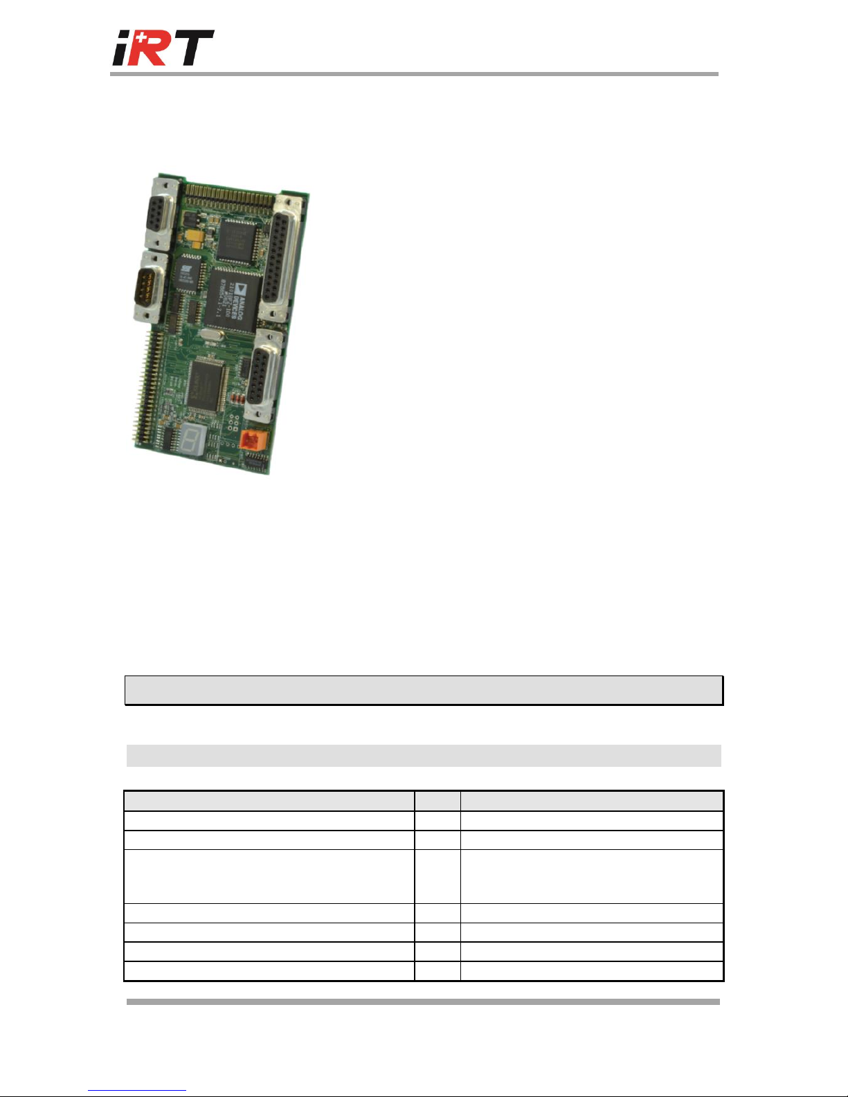
1. Introduction
The servo-amplifiers series 2000 Mini are intended for the control of 3 phases brushless
servo-motors and asynchronous servo-motors.
The motors regulated by the series 2000 Mini servo-amplifiers should have the following
characteristics:
Rotor constructed with permanent magnets or winding cage arranged in 1, 2, 3, 4,
5 or 6 pole pairs, without commutator.
Stator constructed with 3 windings connected in star or delta.
Brushless motors: electronic commutation is performed by means of a feedback
type:
With control unit 2001
Speed one resolver
Incremental encoder with U, V and W signals
With control unit 2002
Absolute encoder SinCos Hiperface® compatible
EnDat 2.1
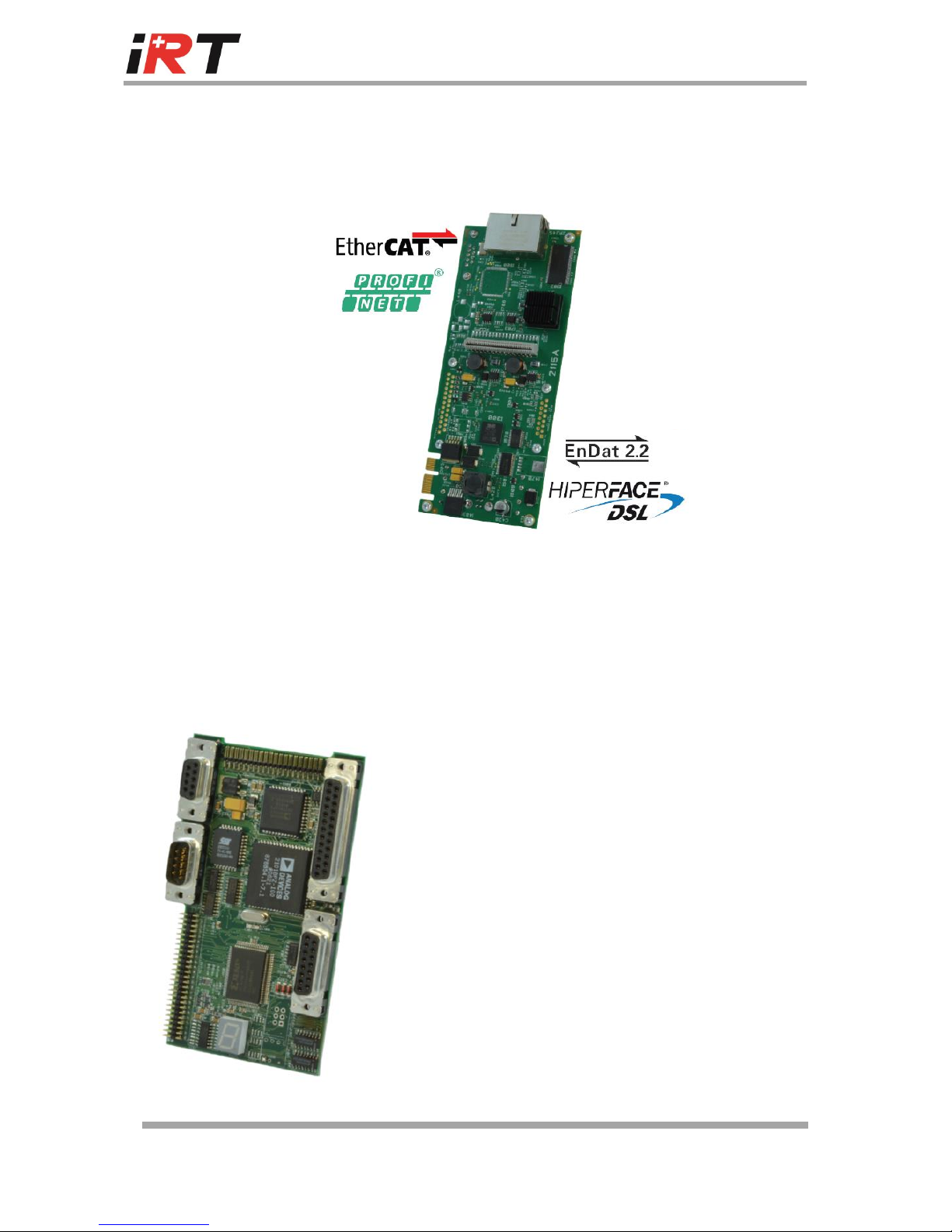
With control unit 2115
Speed one resolver
EnDat 2.1 / 2.2
Hiperface® DSL (single cable solution)
Asynchronous motors: electronic commutation is only performed by means of a
feedback type:
Speed one resolver
Incremental encoder.
Motors with Hall effect sensors and tachogenerator are not suitable.
The servo-amplifiers 2004 MiniEvoultion are fully digital. High-performance torque, speed
and positioning control fulfils all requirements for rapid response and control accuracy.

TECHNICAL MANUAL Drive 2000 Mini Evo
October 2016-Rev. 1 4
Digital control allows comprehensive diagnostics, motor parameters tuning, data and fault
logging, etc.. using a PC based user program.
A wide range of firmware assures to meet the requirements of practically any application.

TECHNICAL MANUAL Drive 2000 Mini Evo
October 2016-Rev. 1 5
The 2004 MiniEvolution is part of the Servo Drive 2000 serie of IRT and thus is very modular,
it can be fitted with 3 different Control units and diverse option boards with the CU2001.
2. Description
The features of the servo-amplifiers series 2000 Mini are described thereunder:
Power supply
Single-Axis unit incorporating braking module
230V single phase (drive 2004)
Power driver
Galvanic isolation between control and power electronics.
IGBT output stage.
Digital PWM current loop providing very low ripple motor currents and high
motor efficiency.
Digital controller
Full-digital servo-amplifier for Brushless motor with resolver.
Easy software update and fully programmable through serial link RS232 or RS485.
Possibility to integrate a customised INTERFACE board.
Natural convection cooling
Multi loops control (torque and speed).
Sinusoidal current output ensures smooth torque and optimal performance at low
speed.
Display for status & diagnostic.

TECHNICAL MANUAL Drive 2000 Mini Evo
October 2016-Rev. 1 6
User's inputs / outputs
A - Control unit 2115
Ethercat ® or Profinet ®
USB port for programming and diagnosis.
External power supply to the Control and Interface boards to keep position data
and alarms in case of main power supply interruption.
B - Control unit 2001
Analogue Speed or Current input command +/- 10V
Digital input command.
Pulse/Dir
SSI command interface
RS232 serial port and RS485 serial port for multi axis
controller system.
Limit switches for overrun protection in both
directions.
External power supply to the Control and Interface
boards to keep position data and alarms in case of
main power supply interruption.
CNC feedback virtual encoder 1024 PPR
Ready relay
With Add-on boards:
CAN interface
24VDC auxiliary supply
Encoder motor feedback
Dual Analogue bipolar output
Profile (motion control by PLC 24V logic)

TECHNICAL MANUAL Drive 2000 Mini Evo
October 2016-Rev. 1 7
C - Control unit 2002
Analogue Speed or Current input command +/- 10V
Digital input command.
SSI command interface
RS232 serial port
Limit switches for overrun protection in both
directions.
External power supply to the Control and Interface
boards to keep position data and alarms in case of
main power supply interruption.
CNC feedback virtual encoder 1024 PPR
Ready relay
Ready relay
Ready relay
Protections
Rugged industrial construction for use in adverse conditions.
Power stage fully protected against short-circuit and over-temperature.
Motor protection by I2t limitation.
Detection of feedback fault, motor wiring failure, motor overheating.
3. Technical data
3.1 General data for all types
Description
Unit
Series 2000 Mini
Supply frequency
Hz
45 to 65
Operating temperature range
° C
0 to 60
Operating temperature range at full power
(from 45°C, reduce output current by 2%/°C to
60°C)
° C
0 to 45
Storage temperature range
°C
-25 to +55
PWM chopper frequency
kHz
7.5
Differential input reference
V
+ 10 to -10
Speed control range
1/32768

TECHNICAL MANUAL Drive 2000 Mini Evo
October 2016-Rev. 1 8
Speed loop bandwidth
Hz
max. 150
Current loop bandwidth
Hz
max. 2000
Output frequency to motor
Hz
0 to 500
Incremental encoder simulation
ppr
1 to 1024 (2048)
Theoretical max. speed for motor with resolver
"speed one"
rpm
7500 or 12000
depending on firmware version
Standard baud rate
Bd.
9600
Serial link
Transmission
Full duplex
Format
1 START bit, 8 DATAS bit, no parity,
1 STOP bit
Time between power on and enable drive
sec
Max. 3
International Protection
IP20
3.2 Specific data
Description
Drive Mini type
Unit
Value
Supply Voltage
2004
VAC
1x110 to 230 +/-15%
Max. output voltage to
motor
All
V
(input AC-10), 3 phases
ON-Switching threshold of
brake module
2004
VDC
400
OFF-Switching threshold of
brake module
2004
VDC
390
ON-Trip threshold of
overvoltage
2004
VDC
420
OFF-Trip threshold of
overvoltage
2004
VDC
410
OFF-Trip threshold of
undervoltage
All
VDC
110
ON-Trip threshold of
undervoltage
All
VDC
100
Cooling
2004
Natural air convection
Indicative weight
All
kg
2.2

TECHNICAL MANUAL Drive 2000 Mini Evo
October 2016-Rev. 1 9
3.3 Power data
Drive
type
Rated rms
current
Rated pk.
current
Max. rms
current
Max. peak
current
Rated
power
Max.
power
(Irms rated)
(Ipeak rated)
(Irms max)
(Ipeak max)
(Prated)
(Pmax)
(A)
(A)
(A)
(A)
(kW)
(kW)
Mini
2004
4
5.7
8
11.3
1.5
3
Note: Irms = Ipeak / 1,41 Vrms= 220V or 390V
P = 1,73 x Irms x Vrms or P = 3 x Irms/phase x Vrms/phase
Braking power :
Drive
type
Rbraking
Peak braking
power
Max. continuous
braking power
Surge energy
(T=300K)
()
(W)
(W)
(J)
Mini
2004
100
1500
100
The surge energy rating is the maximum permitted dynamic brake application from cold. To
a first approximation, heat is then removed at the rate given by the continuous power
figure, thus about 20 seconds interval must be allowed between full energy stops.

TECHNICAL MANUAL Drive 2000 Mini Evo
October 2016-Rev. 1 10
3.3.1 Inrush current
Wave shape for the nominal values
i t i e
p
tT
( )
i t i T
p
2 2
1
2
Series 2000 Mini : ip = 7 A and T = 80ms i2 t = 2.0 A2 s

TECHNICAL MANUAL Drive 2000 Mini Evo
October 2016-Rev. 1 11
3.4 Mini Evo drive outlines

TECHNICAL MANUAL Drive 2000 Mini Evo
October 2016-Rev. 1 12
3.5 Compatible Motors
Brushless 3 phases servo-motors
Asynchronous, 3 phases motors
3.6 Position feedback solutions
Resolver :
Characteristics :
Speed One (1 sine period and 1 cosine period per revolution)
Ratio 0.5 10%
Reference frequency : 5..10 kHz
ZRO 95@ 7,5 kHz (Input impedance)
ZSO 1000@ 7,5 kHz (Output impedance)
Incremental encoder for asynchronous motor only.
Absolute encoder Stegmann SinCos Multi and Single turn SRS/M
50/60(HIPERFACE compatible).
Incremental encoder with U, V and W signals for synchronous
motor.
EnDat absolut (single/multi turn) encoder 2.1 / 2.2
Hiperface ® DSL (single/multi turn) encoder (Single cable solution)

TECHNICAL MANUAL Drive 2000 Mini Evo
October 2016-Rev. 1 13
4. Fuses
Drive Type Mini
DC-BUS (FBUS)
2004
16A/500V 6.3x32
(on line input for the type 2004)
SIBA, art. 70 065 65
UL: E167295
Art. IRT: 2410.158.16
NB : No replacement of any fuse should be carried out until the reason for it’s blowing
has been rectified.
5. Option list
See Control Units
6. Add-on boards
Add-on boards compatible with series 2000 Small drives
IRT PROFILE
Add-on board to perform simple movements and interfacing with 24V systems
(PLS).
Main characteristics :
24 V powered.
DC-DC conversion for drive power back-up (the position value is kept
when main supply of the drive is switched off).
14 Outputs potential free (24V 100 mA).
16 Inputs 24V potential free.
Windows Profile User software for easy setting.
To obtain more information about Profile board, contact your IRT distributor.

TECHNICAL MANUAL Drive 2000 Mini Evo
October 2016-Rev. 1 14
Add-on boards compatible with series 2000 Small drives
UVW ENCODER FEEDBACK
See Special functions specification.
Dual analogic bipolar output
Outputs range : +/- 10V
Output SPEED : 1V corresponds to 1000 RPM
Output CURRENT : 10V corresponds to IMAX DRIVE
Distributed by :
Official IRT distributors.
CAN Add-on
Proprietary CANopen interface module for IRT Series 2000 & 4000 drives.
See Special functions specification.

DRIVE 2000 MINI EVO,TECHNICAL MANUAL EVOLUTION
CHAPTER
PAGE (OLD VERSION)
PAGE
MODIF REV.
DESCRIPTION
1
Manual adapted Technical manual for drives 2000 Mini Evolution
Last modification : October 2016
This manual suits for next models
1
Table of contents
Other IRT Amplifier manuals
Popular Amplifier manuals by other brands

Sony
Sony XM-D1000P5 Marketing Specifications operating instructions

Mondial Designs Limited
Mondial Designs Limited Acurus 200FIVE Owner's Information

Ashdown
Ashdown 22 HEAD user manual

thomann
thomann Harley Benton HB-300B user manual

Martin Audio
Martin Audio MA4.8Q Technical specification

Audio Note
Audio Note P3 Silver Owner's Information