JDS Stargate LCD-96M User manual

LCD MULTI-MENU KEYPAD
LCD-96M
USER MANUAL
INT
ERACTIVE AUTOMATION SYSTEM
T
M
12200 Thatcher Court Poway, CA 92064 U.S.A.
TEL 858-486-8787 FAX 858-486-8789
EMAIL [email protected]
www.jdstechnologies.com
“The Home of Automation”
REV 1.1

Contents ....................................................................................... 2
Overview ....................................................................................... 3
Hole Cut-out Template ................................................................... 4
Installing the LCD-96M enclosure .................................................... 5
Connection using Hub (Homerun wiring) .......................................... 6
Connection using Daisy-Chain wiring .............................................. 7
Setup ........................................................................................ 8
PROGRAMMING AND OPERATION
Programming and Operation Introduction ........................... 9-10
Using Bitmapped Graphics ............................................................. 11
Custom Actions
Then Actions ....................................................................... 12
X-10 Two-Way ...................................................................... 13
Pre-Defined Menus
Thermostat ..................................................................................... 14
Voice Mail ...................................................................................... 15
Time Label ..................................................................................... 16
Variable ........................................................................................ 17
Caller ID ........................................................................................ 18
DigitPad ........................................................................................ 19
TelePad ........................................................................................ 20
Time Display ................................................................................. 21
Then LCD Keypad Actions
Then Keypad Actions............................................................... 22
LED Actions ....................................................................... 23
Backlight Actions ....................................................................... 24
Writing Text ................................................................................... 25
Changing Text ................................................................................ 26
Inverting Text ................................................................................ 27
Glossary ........................................................................................ 28
Bitmap Library ....................................................................... 28
Specifications .................................................................................. 28
Troubleshooting .............................................................................. 29
CONTENTS
2

OVERVIEW
3
The LCD-96M is a versatile, easy-to-use, menu-driven keypad that allows control of lighting, heating/cooling, security, home theater,
audio/video, pool/spa, irrigation, voice mail, and other systems connected to Stargate. Up to 96 interactive menu screens canbe created
anddownloadedtotheLCD-96Mbytheuser/installerwiththeincludedEventManagersoftware. Eachmenuline(upto8permenu)can
consist of text (up to 10 letters across) or bitmapped graphics (.bmp format, 64 x 16 pixels).
8 Dual-Position Rocker Buttons, located to the right of the menu display, can be individually programmed to perform different functions
depending on the menu selected. The Left and Right side of each button can be programmed independently (such as left = off, right = on)
orperformthe same function (such as go to Main menu). Programmable functions include: Navigational functions (go to menu, previous
menu), Then Actions (X-10, IR, Relay, Macro, VoiceMail, Flag, Variable, Audio Path) and Predefined Menus (Thermostat, VoiceMail,
TimeLabel, Variable, Caller ID, DigitPad, TelePad, Time Display). A special Two-Way X-10 feature allows any X-10 address to be
assigned to a rocker button. Pressing once on the right or left side of the button turns the X-10 device On or Off. Holding down the right
or left side of the button Brightens or Dims. On/Off status is indicated by a normal (Off) or reversed (On) background on the associated
menu line for easy viewing, even from a distance.
IndividualmenuscreensorcompletesetupscanbedownloadedtokeypadsviathesharedRS-485connectionorstoredondiskastemplates
andlater loaded tokeypads as needed. Menuline items canbecut, copied andpasted from anymenuto anotherforeasy editing. Keypads
can also be programmed and edited remotely via modem.
Three LEDs (red, green and yellow), located above the rocker keys, can be individually instructed (from the Event Manager schedule) to
turn on, turn off, blink fast or blink slow based on any condition(s).
The LCD-96M has a built-in high-contrast green backlight that can be programmed to stay on continuously or turn on with any key press
thentimeoutafteraspecifieddelaytime. ThebacklightandmenuselectionscanalsobeaccessedviatheEventManagerscheduletoallow
dynamic interaction with other system functions.
Upto16LCD-96MKeypadscanbeconnectedina"daisy-chain"toStargate'sRS485portusingtwotwistedpairsofcatagory-5cable(one
pair for communication and the other for 12vdc power) or homerun (star wired) to an optional RS-485 hub. Up to 4 LCD-96M Keypads
can be powered by Stargate's on-board 12vdc power supply. Five or more keypads require an external 12vdc power supply.
The LCD-96M faceplate measures 4"W x 4 3/4"H and snaps into an included wall-mount enclosure (3 3/8"W x 4"H x 2"D) for easy
installation.
Dual-Position
Rocker Buttons
LED Indicators
Vent
Menu Lines
LCD Menu Screen Stores 96 User-Defined Menus & Sub-Menus
Programmable from Event Manager software
Supports Text & Graphics (.bmp)
8 Dual Position Rocker Keys
Independent Left/Right Programming
3 Programmable LEDs (On/Off/Blink)
Continuous or Timed Backlight
VoiceMail Menu
Caller ID Name & Number Log
Thermostat Menu With 16 Zone Access
Reliable RS-485 Communication
Simple 4-Wire Connection
Low Current Draw (100ma @ 12vdc)
Colors: White, Black, Custom
.
.
.
.
.
.
.
.
.
.
.
.
.
.

LCD MULTI-MENU KEYPAD
LCD-96M
4"
3 3/8"
Hole Cut Out
Template
4
RS-485 Connector
POT1
Screen
Contrast
Adjust

Lock Wings
(open)
INSTALLING THE LCD-96M
1) Choose a convenient location to install the LCD-96M Keypad. For best visability, install the keypad at eye level.
2) Using the Hole Cut-Out Template on the previous page, put a small pencil mark on the wall in the four corners of the cut-out.
3) Draw lines to connect the four pencil marks.
4) Check that the horizontal lines are level prior to cutting out the hole.
5) Carefully cut out the 3 3/8" x 4" hole with a dry wall utility knife.
6) Slide the Catagory-5 cable through the access hole in the back of the enclosure.
7) Insert the enclosure into the wall with the lock wings closed flush against the top and bottom of the enclosure (figure 1).
Be sure the side marked "THIS SIDE UP" on the back of enclosure lip is facing up and the lock wings are back far enough behind
the enclosure lip to accommodate the thickness of the wall (figure 2).
8) Once inserted, lock the enclosure in place by tightening the two lock wing screws.
9) Terminate the four wires of the Catagory-5 cable onto the screw terminal connector (figure 3) and plug into back of keypad.
10) Place the top of the keypad over the top lip of the enclosure then carefully snap the bottom in place (figure 4).
Catagory-5
cable
Lock Wings
(closed) “THIS SIDE UP”
Lock Wing
Screws
Figure
1Figure
2Screw
Terminal
Connector
Figure
3
Screw Terminal Connector
+12vdc
GND
B+
A-
Orange
White-Orange
Blue
White-Blue
Green
White-Green
Brown
White-Brown
CATAGORY-5CABLE
Not Used
Figure
4
5
}

Keypad #1 Keypad #2 Keypad #3 Keypad #4
Keypad #8Keypad #7Keypad #6Keypad #5
RS-485 HUB #1
RS-485 HUB #2
Keypad #16Keypad #15Keypad #14Keypad #13
Keypad #9 Keypad #10 Keypad #11 Keypad #12
To RS-485 HUB #3
Catagory-5
Cable
+12v
GND
B+
A-
STARGATE
RS-485 Connector
6
CONNECTION USING RS-485 HUB AND HOME-RUN (STAR) WIRING
An optional RS-485 Hub can be used to allow home-run (star format) wiring of keypads to Stargate. The RS-485 Hub can accom-
modate up to 8 RS-485 devices (keypads, thermostats, etc.). Additional hubs can be connected to accommodate up to 32 devices.
NOTE: Each hub requires an external 12vdc @ 1A power supply. DO NOT power a hub from Stargate's 12v power
source. When connecting two or more hubs, the RS-485 inputs and ground connection of each hub should be connected in a "daisy-
chain" configuration (see diagram). Catagory-5 twisted-pair cable is recommended for all RS-485 connections. Total cable length
should not exceed 4,000 feet.
B+
A-
+12vdc
Ground
12vdc
@1A
Power
Supply
12vdc
@1A
Power
Supply
B+
A-
+12vdc
Ground

CONNECTION USING DAISY-CHAIN (LOOP) WIRING
Up to 16 LCD-96M Keypads can be connected in a "daisy-chain" to Stargate's RS485 port using two twisted pairs of catagory-5 cable (one pair
for communication and the other for 12vdc power). Up to 4 LCD-96M Keypads can be powered by Stargate's on-board 12vdc power supply.
Total cable length should not exceed 4,000 feet.
+12vdc
Ground
B+
A-
STARGATE
RS-485
TERMINALS
Keypad #1 Keypad #2 Keypad #3 Keypad #4 Keypad #5
12VDC
POWER
SUPPLY
+12v
Ground
Catagory 5 Twisted Pair Cable (max length 4,000 ft.)
+12vdc
Ground
B+
A-
12VDC
POWER
SUPPLY
+12v
Ground
Whenconnecting anexternal12vdc power source atthekeypad location,adda 100-ohm, 1watt resistorinseries withtheground wire feeding the
keypads.
When connecting 5 or more LCD-96M keypads, an external 12vdc power source is required. Allow 100mA for each LCD-96M. If the external
12vdc power source is located near Stargate, connect the NEGATIVE (Ground) wire of the power supply to the GROUND terminal of Stargate's
RS-485 connector.
+12vdc
Ground
B+
A-
STARGATE
RS-485
TERMINALS
Keypad #1 Keypad #2 Keypad #3 Keypad #4
Catagory 5 Twisted Pair Cable (max length 4,000 ft.)
100-OHM
1 WATT
RESISTOR
7
Catagory 5 Twisted Pair Cable (max length 4,000 ft.)

SETUP
8
1) Connect 12vdc power and RS-485 network pair (B+, A-) to the keypad(s).
(NOTE: Some Stargate RS-485 connectors are labeled "TRB" instead of B+ and "TRA" instead of A-)
If an external 12vdc power supply is used, you MUST connect the ground (negative) of the power supply to the ground (-) terminal
of Stargate. The 3 LEDs will blink for several seconds as Stargate establishes communication with the keypad.
2) After the LEDs stop blinking, press and hold the top button (either side) until the Setup menu screen appears (about 6 seconds).
NOTE: Setup can only be accessed from the Main Menu (Menu #1) top button.
3) If the screen appears blank or faint, using a small screwdriver, slowly turn the tiny screen contrast control ("POT1") near the
RS-485 connector on the back of the keypad (see page 4).
4) Set the keypad address to a number from 1 to 16 using the #2 button labeled "Addr". Press the right side of the button to
increment or the left side to decrement. NOTE: Each LCD-96M must be set to a different address number.
5) Set the default menu screen number (menu screen to go to after timeout) to a number from 1 to 96 using the #3 button labeled
"Default Scrn". For Main Menu set to 1.
6) Set the default menu screen timeout (seconds) using the #4 button labeled "Scrn Tout". Set to "00" to disable the timeout or a
number from 15 - 255 seconds. If a menu is selected from the keypad, it will revert back to the default menu after the menu screen
timeout. Menus selected from the schedule using "Goto Menu" will not timeout.
7) Set the display backlight timeout using the #5 button labeled "Bklt Tout". Set to "00" to keep backlight on continuously or a
number from 15 - 255 seconds to have it turn off after the selected number of seconds have elapsed since the last button press.
8) Set the Time Display Format (12 hour or 24 hour) using the #6 button labeled "TimeFrmt".
9) Select CallerID Auto Display on/off using the #7 button labeled "AutoCID".
When CallerID Auto Display is on, the menu screen automatically switches to the Caller ID display menu on incoming calls.
To function, your phone line must be equipped with Caller ID service and Caller ID must be enabled in the WinEVM Define -
Telephone field.
10) Press the bottom (#8) button to return to the Default (Main) Menu.
Press and hold the top button
to access the Setup menu.
Setup
Ver:1
Addr: 1
Default
Scrn 0
Scrn Tout:
00 sec
Bklt Tout:
00 sec
TimeFrmt
12 hour
AutoCID:
ON
<< Main
Sets Keypad Address
Sets Default Menu
Sets Menu Screen Timeout
Sets Backlight Timeout
Sets Time Display Format
Return to Main Menu
Sets Auto Display Caller ID

PROGRAMMING AND OPERATION - Introduction
35
1) Open Event Manager for Windows (WinEVM).
2) Click DEFINE - LCD KEYPAD.
3) Select the LCD Keypad address you want to program then click DEFINE to open the LCD KEYPAD programming utility.
4) Click the SETUP KEYPAD button.
5) Enter a name and location for the keypad. Set or change the timeout parameters (if not already set at keypad). Click Apply then OK.
4
6)Clickthe "Select" button in the MENU SCREEN SELECT section to select the Menu number you want to program then type a name for
the menu (ie: "MAIN") in the "Name" box.
7) Click on an ACTION you want to assign to a keypad button, then drag the action onto the menu screen (to the left of the desired keypad
button). This will bring up an edit field for the type of action selected.
8) Complete the edit field then click OK to accept the action or CANCEL to escape.
NOTE: The left and right side of a keypad button can each be programmed to perform different actions.
Click the "RIGHT BUTTON SAME AS LEFT" box when you want both sides to perform the same action.
9) Repeat step 7 for each button in the menu you want to program.
10) Click DOWNLOAD MENU to load the LCD-96M with the new menu or select another Menu number to program and repeat steps 6
- 9.
11) To download all defined menus to the LCD-96M, click DOWNLOAD ALL. This may take a few minutes depending on the number
of menus and content (text/graphics) being downloaded. It is not necessary to DOWNLOAD ALL menus if each menu is downloaded
individually.
12) Click OK to exit.
9
7
Drag the action onto
the menu screen
6
12
11
10 CopyKeypad
Select

PROGRAMMING AND OPERATION - Introduction
BUTTON ACTIONS
There are three types of button actions that can be assigned, Custom, Navigation and Predefined Menu.
CUSTOM (Then Action, X-10 Two-Way)
Then Actions include X-10, IR, Relay, Macro, VoiceMail, Flag, Variable, HVAC, Audio Path, LCD Keypad and are treated the
same as Then Actions used in the schedule.
X-10 Two-Way action allows single button X-10 control of on, off, dim and bright functions with on/off status indication (inverted
background = on, normal = off).
NAVIGATION
Navigational functions include "do nothing", "go to menu"and "previous menu". These allow switching to specific menus or previ-
ous menu. "Do nothing" prevents the associated keypad button from performing any action but the menu line can still
display text or graphics.
PREDEFINED MENUS
PredefinedMenusaremenusscreenswithpre-definedfunctionandlayout. TheyincludeThermostat,VoiceMail,TimeLabel,Variable,
Caller ID, DigitPad and TelePad. Time Display is a single pre-defined Menu Line. The bottom button of the Thermostat, VoiceMail,
CallerID,DigitPadandTelePadmenusreturnstotheMainMenu(leftbutton)orPreviousMenu(rightbutton). Theseareidentifiedwith
the graphic for "Main" menu and for "Previous" menu.
SIZE
Selects the type size of the text on a menu line. 5 x 7 supports up to 10 characters. 6 x 8 supports up to 8 bold characters.
ALIGNMENT
Selects the vertical placement of the text on a menu line.
JUSTIFY
Selects the horizontal placement of the text on a menu line.
CUT, COPY, PASTE, DELETE, EDIT
Performs the corresponding function to the selected menu line.
COPY KEYPAD
Copies all menus from the selected keypad to another keypad.
DOWNLOAD SCREEN / DOWNLOAD ALL
Download Screen loads only the displayed menu into the LCD-96M keypad.
Download ALL loads all defined menus into the LCD-96M keypad.
10
CopyKeypad
10:19 PM
96
Select

PROGRAMMING AND OPERATION - Using Bitmapped Graphics
Using Bitmapped Graphics
Manymenu items allow the use of bitmapped graphics inplaceof text for labeling a menu line. Graphics canenhancethe look of amenu
andsimplifyidentifyingthefunctionofabutton. Forinstance,usingupanddown arrowsinplaceofthewords"up"and"down"simplifies
the thermostat menu. A library of useful menu graphics is included with WinEVM versions 2.43 and higher. Each LCD Keypad address
can have a unique library of up to 48 bitmapped graphics.
Creating Bitmapped Graphics
Bitmapped Graphics can be created in Microsoft Paint or any other graphics program that supports bitmapped graphics. Bitmapped
Graphics used in menus mustbestoredas.bmpfiles sized to 64 x 16pixels, black& whiteonly inthe STARGATEfolder (orfolder
containing your schedule and database files).
To create a new bitmap graphic in MicroSoft Paint:
1) Click FILE - NEW
2) Click "Image" then click "Attributes" to bring up the Attributes field. Type 64 in the "Width" box. Type 16 in the "Height" box.
Select "Pels" in the Units section. Select "Black and White" in the Colors section. Then Click OK.
3) Draw the desired bitmap. Click the Magnifier Tool to enlarge the workspace if necessary.
4) Click FILE - SAVE and select the STARGATE folder (or folder containing your schedule and database files), type a name for the
bitmap then click OK.
To place a graphic onto a menu line:
1) Select "bitmap" then click "Select" in the Display Attributes section. This will bring up the Bitmap Select menu.
2) Click on the desired Bitmap name or graphic in the list then click OK.
To add a new bitmap to the list, click on a blank line in the Bitmap Select list then click "ADD" and select the desired bitmap.
NOTE: Size, Alignment and Justify do not apply to graphics.
11

PROGRAMMING AND OPERATION - Custom Actions
Then Actions
Selecting Then Action will bring up the Then Action field. In the DISPLAY ATTRIBUTES section, type the name you want to appear on
the menu line (up to 10 characters) or select a bit map graphic. Graphics used in menus must be stored in the STARGATE folder or folder
containing your schedule (.sch) and database (.dbf) files. In the BUTTON ACTION section, click NEW under the LEFT Button heading
to bring up the button action choices for the LEFT side of the rocker button. Select the desired Then Action. Do the same for the RIGHT
Button if you want the RIGHT side of the rocker button to perform a different Then Action, then click OK. Otherwise check the "RIGHT
BUTTON SAME AS LEFT BUTTON" box to assign the same function to both sides, then click OK.
ThenActionstriggered byabutton aretreatedthesameasthoseusedin theEventManager schedule. ForcompletedetailsonThenActions,
refer to the "THEN/ELSE Actions" section of your Stargate User Manual.
12
When a Then Action button is pressed, the programmed action will be executed.
Copy Keypad

X-10 Two-Way
Selecting X-10 Two-Way as a menu item will bring up the X-10 field. Select the X-10 device you want to control in the X-10 Device List
then type the name you want to appear on the menu line (up to 10 characters). Double-clicking the name in the list will insertthe first 8 or
10 characters of the name into the text box (depending on size selected). Graphics used in menus must be stored as .bmp files sized to 64
x 16 pixels, black & white only in the STARGATE folder (or folder containing your schedule and database files).
PROGRAMMING AND OPERATION - Custom Actions
13
When the RIGHT side of the X-10 button is pressed, Stargate sends the associated ON command. When the LEFT side of the X-10 button
ispressed,StargatesendstheassociatedOFFcommand. HoldingdowntheRIGHTsideofthebuttonBRIGHTENS,holdingdowntheLEFT
side DIMS. When the associated X-10 device is in the ON state, the name on the the menu line is inverted (black background with green
text). Whenthe associated X-10 device is in the OFFstate,the name on the the menu line isnormal(black text on green background). The
On/Off status indication will also respond to any X-10 controller.
Right Button sends ON command
(Hold Down to Brighten)
Left Button sends OFF command
(Hold Down to Dim)
Normal Text indicates
device is OFF
Inverted Text indicates
device is ON
Select
Copy Keypad
PROGRAMMING AND OPERATION - Pre-defined Menus
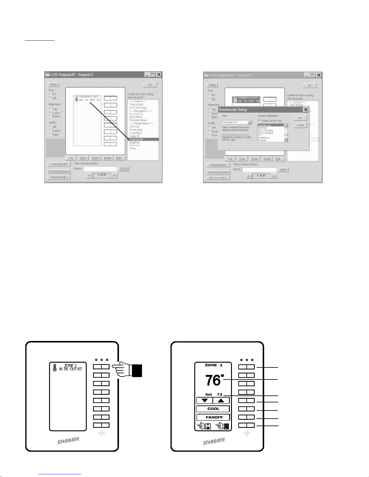
Whenthe Thermostatbutton (eitherside)is pressed,thedisplay switchesto theThermostatmenu. Thethermostat menudisplays zone
name, temperature, set point, mode (heat/cool/auto/off) and fan status (on/off) and allows control of set point, mode and fan. Up to 16
thermostatzonescanbedefinedandaccessedfromthethermostatmenu. Pressingthetop(#1)buttonselectsthethermostatzone. RCS
RS-20 Remote temperature sensors are treated as separate zones and can also be displayed by a thermostat menu.
Outside temperature can also be displayed on the bottom half of the menu line by clicking the "DISPLAY OUTSIDE TEMP" box and
selecting a defined variable in the list below it. The variable must be loaded with the outside temperature value from an analog input,
RS-20 Remote temperature sensor or other source, then updated to the keypad with an event in the Event Manager schedule using the
THEN - LCD VARIABLE UPDATE action. Example:
EVENT: Update Outside Temp Variable to LCD-96M
If
(A/D:Outside Temp) changes value
Then
(V:Outside Temp) LOAD with (A/D: Outside Temp)
LCD: Update LCD Variable <V:Outside Temp> [KP:ALL]
Delay 0:15:00
End
Thermostat
SelectingThermostatasamenuitemwillbringuptheThermostatSetupfield. SelecttheThermostatZonetobedisplayedontheThermostat
menu line (to the left of the associated keypad button). The Thermostat menu line will display the name of the zone (first 8 letters) in the
upper half of the menu line and the current temperature on the bottom half.
Current Temperature
Set Point
Adjusts SET POINT
Selects MODE
Controls FAN (On/Off)
Main Menu / Previous Menu
Selects ZONE
14
Select

VoiceMail
Selecting VoiceMail as a menu item will bring up the VoiceMail selection field. Select a mailbox number and the desired output for
playing back voicemail messages then click OK. This will display the Box Number on the left side of the menu line and the number
of NEW and OLD messages on the right side.
WhentheVoiceMailbuttonispressed, thedisplay switchesto theassociated VoiceMailmenu, withpre-defined buttonsfor Play/Skip,
Repeat/Stop,Back 5Seconds/Forward 5Seconds, PlayAll New&Old Messages/PlayNew MessagesOnly andDelete. The topmenu
line of the VoiceMail menu displays the Box Number and number of new and old messages in the mailbox.
PROGRAMMING AND OPERATION - Pre-defined Menus
Play 1st / Skip (next)
Repeat / Stop
Back 5 sec. / Forward 5 sec.
Play All / Play New
Delete
Main Menu / Previous Menu
15
Select Select

PROGRAMMING AND OPERATION - Pre-defined Menus
Time Label
Selecting Time Label as a menu item will bring up the Time Label field. Select the Time Label you want to control then type the name
you want to appear on the menu line (up to 10 characters) or select a bit map graphic then click OK. Double-clicking the name in the
list will insert the first 8 or 10 characters of the name into the text box (depending on size selected).
When the Time Label menu button is pressed, the screen switches to the Time Label menu. The top menu line of the Time Label
menu displays the name you assigned. The next menu line lists the days of the week by first letter (SMTWTFS). Pressing the
RIGHT side of button #2 scrolls through each day. An underline below the letter indicates the selected day. Pressing the LEFT
side of button #2 inserts or removes an asterik (*) below the selected day(s). The asterik indicates the day(s) the Time Label is
in effect. The next menu line down displays the time of day the Time Label is in effect. Button #4 ("HR") sets the Hour (left side
decrements, right side increments). Button #5 ("MIN") sets the Minutes (left side decrements, right side increments). Button#7
("CANCEL") returns to the previous menu without saving any changes. Button #8 ("OK") enters the new Time Label data and
returns to the previous menu.
NOTE: In order for a TimeLabel to be controlled exclusively from the keypad, deselect all the days of the week when defining
the Time Label in WinEVM and select "TimeLabels" in the download options. Once downloaded, the TimeLabel can only be
programmed by a keypad. (If a "Touchtone to TimeLabel" function is used in the schedule, it can change the TimeLabel time but
notthe day ofthe week.) Deselect "TimeLabels"in thedownloadoptions forfuture downloads, otherwiseany settingsmadefrom
the keypad will be overwritten. Software/Firmware updates will clear Time Label settings. It is necessary to reset Time Label
settings from a keypad after updating software/firmware. Changes made to Time Label settings from a keypad will not appear
in the WinEVM Define - Time Label field.
Set-Clear/DaySelect
Decrement Hour/Increment Hour
DecrementMinutes/Increment Minutes
Go To Previous Menu Without Saving
Save Changes & Go To Previous Menu
16
Select
Copy Keypad

Variable
Selecting Variable as a menu item will bring up the Variable field. Select the variable whose value is to be displayed on the menu item
(to the left of the associated keypad button). Type the variable name (up to 8 characters) to be displayed above the numerical value.
Double-clicking the name in the list will insert the first 8 or 10 characters of the name into the text box (depending on sizeselected).
PROGRAMMING AND OPERATION - Pre-defined Menus
WhentheLCDVariablemenuitembuttonispressed,thedisplayswitchestotheLCDVariablemenu. TheLCDVariablemenudisplays
the variable value and allows the variable to be incremented or decremented by pressing the + or - side of button #3.
075
Decrement / Increment
Go To Previous Menu Without Saving
Save Changes & Go To Previous Menu
17
TominimizetrafficontheRS-485network,updatingthedisplayedvariablevaluerequiresaneventintheEventManagerscheduleusing
the THEN - LCD VARIABLE UPDATE action. Example:
EVENT: Update Humidity Variable to LCD-96M
If
(A/D:Humidity) changes value
Then
(V:Humidity) LOAD with (A/D: Humidity)
LCD: Update LCD Variable <V:Humidity> [KP:ALL]
End
Select
Copy Keypad Copy Keypad

Caller ID
SelectingCallerIDasamenuitemwillbringuptheCallerIDfield. Typethenameyouwanttoappearonthemenuline(upto10characters)
or select a bit map graphic then click OK.
PROGRAMMING AND OPERATION - Pre-defined Menus
When the Caller ID button is pressed, the display switches to the Caller ID menu which stores and displays Caller ID data (time, date,
numberandname)forthelast50calls. Themostrecentcallislistedfirst. Pressingtheleftorrightarrowbuttonallowsyoutoscrollthrough
and review previous calls.
Main Menu / Previous Menu
Previous Call / Next Call
Date
Time
Phone Number
Name
18
Select
Copy Keypad

DigitPad
SelectingDigitPadasamenuitemwillbringuptheDigitPadfield. Typethenameyouwanttoappearonthemenuline(upto10characters)
or select a bitmapped graphic then click OK. Graphics used in menus must be stored as .bmp files sized to 64 x 16 pixels, black & white
only in the STARGATE folder (or folder containing your schedule and database files).
PROGRAMMING AND OPERATION - Pre-defined Menus
19
When the DigitPad menu item button is pressed, the display switches to the DigitPad menu. The DigitPad menu contains pre-labeled
buttonssimilartoatelephonekeypad. WhileaDigitPadbuttonispressed,thecorrespondingmenulineinvertstoconfirmthe buttonpress.
Programmingany singlebutton press orsequence ofbuttonpresses toperform an actionrequires aneventin theEventManager schedule
using the IF - LCD KEYPAD condition.
The DigitPad can serve as a security keypad with multiple access codes to arm and disarm a connected security panel. This requires an
"armed"outputfromthesecuritypanelconnectedtooneofStargate'sdigitalinputsandoneofStargate'srelays(COMandN.O. terminals)
connected to a security panel zone programmed for "KEYSWITCH" operation. Example:
EVENT: Security Access Code
If
LCD Seq:'1 2 3 4 ' Received within 4 seconds
Then
(RELAY:Security) ON
DELAY 0:00:01
(RELAY:Security) OFF
DELAY 0:00:02
If (DI:Armed) is OFF
Then
LCD: Red LED OFF [KP:ALL]
Voice:SECURITY SYSTEM DISARMED [Spkr]
Else
LCD: Red LED Blink Slow [KP:ALL]
Voice:SECURITY SYSTEM ARMED [Spkr]
Nest End
End
Main Menu / Previous Menu
Select Select

PROGRAMMING AND OPERATION - Pre-defined Menus
TelePad
Selecting TelePadas a menuitem willbring up theTelePad field. Type the nameyou want toappear onthe menu line(up to10 characters)
or select a bitmapped graphic* then click OK. Graphics used in menus must be stored as .bmp files sized to 64 x 16 pixels, black & white
only in the STARGATE folder (or folder containing your schedule and database files).
Main Menu / Previous Menu
20
* Graphics used in menus must be stored in the STARGATE folder as .bmp files sized to 64 x 16 pixels, black & white only.
When the TelePad menu item button is pressed, the display switches to the TelePad menu. The TelePad menu contains pre-labeled
buttons similar to a telephone keypad and performs the same functions as a telephone on the ICM line. For example, if the Telephone
Parameters are defined for 90 Codes, pressing * 1 1 on the TelePad will instruct Stargate to issue an A-1 ON X10 command. Any event
programmedto respondto a touchtone sequence canalsobecontrolled fromthe TelePad menu. Note: TelePadcannot triggeran event
that includes On-Hook or Off-Hook conditions in the telephone sequence. While a TelePad button is pressed, the corresponding menu
line inverts to confirm the button press.
Select Select
Table of contents
Popular Keypad manuals by other brands

Crestron
Crestron Cameo C2NI-CB Series Operations & installation guide

Vantec
Vantec Mobile Keypad with Dual USB Hub NBK-MH100 Specifications

CAMDEN
CAMDEN Invision CV-920 Series installation instructions

Satel
Satel INT-SF Quick installation guide

INIM
INIM Aria Installation and programming manual

AMX
AMX Metreau DAS-MET-6SRC installation guide

GE
GE Interlogix Aritech ATS1155 quick start guide

Gianni Industries
Gianni Industries DK-100 Operation user's manual

Hyundai Mobis
Hyundai Mobis RKE-4F19 user manual

AT&T
AT&T 1035 Identification and Connections

Neets
Neets UniForm installation guide

First Alert
First Alert FA260KP-OM installation instructions


