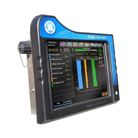
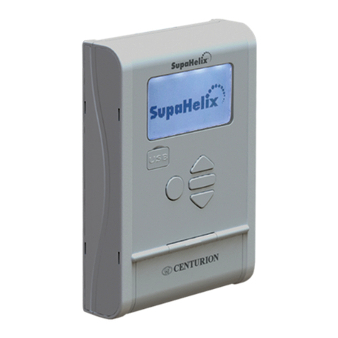
JEAN LUTZ TARALOG User manual

Version TG2TCT231FR
Version TG2TCT231EN Fr
En DUC
2 rue du Forbeth – 64110 JURANÇON – France
__________
TG2TCT231DUCFrEn.doc
Français/English

Manuel d'utilisation du TARALOG 2/102
SOMMAIRE
INSTALLATION.................................................................................................................................6
SITUATION DES DIFFERENTS ELEMENTS.......................................................................................7
MONTAGE DU TARALOG ...........................................................................................................8
CONNECTION DES CABLES DANS LES BOITIERS ............................................................................8
BOITIER DE CONNEXION B2FJ1 (B2TJ) .......................................................................................9
ALIMENTATION ELECTRIQUE DU TARALOG.................................................................................9
OMBILICAL ET BOITIER B1FB1 (B1TS2) ....................................................................................10
MONTAGE DES BOITIERS B1FB1 (B1TS2).................................................................................11
CAPTEUR DE ROTATION VR28 ..................................................................................................13
CAPTEUR DE PROFONDEUR F89................................................................................................14
CAPTEURS C16 400.................................................................................................................15
MONTAGE DE L'INCLINOMETRE IA1620 SUR LE MAT ...................................................................16
ENROULEUR DE CABLE DC7 (OPTION)......................................................................................17
MONTAGE DU SEPARATEUR SP400 (OU SP500) ......................................................................18
RADIO R801.............................................................................................................................19
RADIO R511.............................................................................................................................20
RADIO R411.............................................................................................................................21
INTRODUCTION .............................................................................................................................22
GENERALITES SUR LES MODES..................................................................................................22
FACE AVANT - CLAVIER .............................................................................................................26
MODE "VEILLE" .............................................................................................................................28
ECRAN DE "VEILLE".................................................................................................................28
MODE "DEBUT DE PIEU"..............................................................................................................30
MODE "MESURE" ..........................................................................................................................34
PHASE "FORAGE"...................................................................................................................34
PHASE "BETONNAGE" ...........................................................................................................37
MEMOTEL.......................................................................................................................................43
RADIOS R801 / R511 / R411 ..........................................................................................................45
MEMOBLOC....................................................................................................................................49
LECTURE DU CONTENU DU MEMOBLOC ..................................................................................49
POSITIONNEMENT AUTOMATIQUE DU MAT (OPTION).............................................................51
MODE "PROGRAMMATION".........................................................................................................54
TABLEAU DE PROGRAMMATION – TARALOGG VERSION TG2TCT231FR ..................................56
DESCRIPTION DES MENUS ET SOUS-MENUS ...............................................................................60
Menu 1 – Capteurs........................................................................................................60
Sous-menu 11 – Déplacement tarière .................................................................60
Sous-menu 12 – Débit et Volume béton..............................................................61
Sous-menu 13 – Vitesse de rotation....................................................................65
Sous-menu 14 – Zéro pression béton..................................................................66
Sous-menu 15 – Zéro couple de rotation.............................................................66
Sous-menu 16 – Unité CR + coefficient...............................................................66
Sous-menu 17 – Zéro inclinaison X.....................................................................73
Sous-menu 18 – Zéro inclinaison Y.....................................................................74
Sous-menu 19 – Zéro traction (option) ................................................................75

Manuel d'utilisation du TARALOG 3/102
Sous-menu 1A – Zéro poussée ...........................................................................75
Menu 2 – MEMOBLOC .................................................................................................76
Sous-menu 21 – Sélection numérique.................................................................76
Sous-menu 22 – Pas d'acquisition.......................................................................76
Sous-menu 23 – Mode "MEMOLEC"...................................................................77
Menu 3 – Heure et Date ................................................................................................77
Sous-menu 31 – Réglages...................................................................................77
Menu 4 – Configuration… .............................................................................................78
Sous-menu 41 – Profon. maxi./Profil Surc...........................................................78
Sous-menu 42 – Echelles graphiques .................................................................78
Sous-menu 43 – Bargraphe.................................................................................80
Sous-menu 44 – Auto zero press. béton..............................................................80
Sous-menu 45 – Caractéristiques tube................................................................81
Sous-menu 46 – Slump et Bon Livraison.............................................................82
Sous-menu 47 – Numéro de machine .................................................................82
Sous-menu 48 – Saisie commentaire..................................................................83
Sous-menu 49 – Mode CFA/Kelly........................................................................83
Sous-menu 4A – Envoi E–Mail ............................................................................83
Sous-menu 4B – Impression (TP110)..................................................................84
Menu 5 – Automatisme .................................................................................................85
Sous-menu 51 – Consignes remontée.................................................................85
Sous-menu 52 – Reg. Vanne remontée...............................................................85
Sous-menu 53 – Positionnement du mât (option)................................................88
CHARGEMENT D'UN NOUVEAU PROGRAMME .........................................................................91
"MENUS CACHES" DU TARALOG ...............................................................................................92
CARACTERISTIQUES TECHNIQUES .........................................................................................102

Manuel d'utilisation du TARALOG 4/102
SUMMARY
INSTALLATION.................................................................................................................................6
LOCALIZATION OF THE ELEMENTS................................................................................................7
INSTALLATION OF THE TARALOG ...............................................................................................8
CONNECTION OF CABLES IN THE JUNCTION BOXES .......................................................................8
CONNECTION BOX B2FJ1 (B2TJ) ...............................................................................................9
TARALOG ELECTRICAL POWER SUPPLY .....................................................................................9
UMBILICAL AND CONNECTION BOX B1FB1 (B1TS2)...................................................................10
UMBILICAL AND CONNECTION BOX B1FB1 (B1TS2)...................................................................11
ROTATION SENSOR VR28 .........................................................................................................13
DEPTH SENSOR F89 .................................................................................................................14
C16 400 SENSORS...................................................................................................................15
MOUNTING OF THE IA1620 INCLINOMETER TO THE MAST ...........................................................16
INSTALLATION OF THE EXTENSION DC7 (OPTIONAL)...................................................................17
INSTALLATION OF THE SP400 (OR SP500) SEPARATOR.............................................................18
RADIO R801.............................................................................................................................19
RADIO R511.............................................................................................................................20
RADIO R411P ..........................................................................................................................21
INTRODUCTION .............................................................................................................................22
GENERAL DESCRIPTION OF THE MODES .....................................................................................22
FRONT PANEL - KEYBOARD .......................................................................................................26
WATCH MODE................................................................................................................................28
"START NEW PILE" MODE ...........................................................................................................30
"MEASURING" MODE....................................................................................................................34
MEMOTEL.......................................................................................................................................43
RADIOS R801 / R511 / R411 ..........................................................................................................45
MEMOBLOC....................................................................................................................................49
AUTOMATIC MAST POSITIONING (OPTION)...............................................................................51
"PROGRAMMING" MODE..............................................................................................................54
PROGRAMMING TABLE - TARALOG VERSION TG2TCT231EN ..................................................58
DESCRIPTION OF MENUS AND SUB-MENUS .................................................................................60
Menu 1 – Sensors .........................................................................................................60
Sub-menu 11 – Depth..........................................................................................60
Sub-menu 12 – Flow and Volume........................................................................61
Sub-menu 13 – Rotation speed ...........................................................................65
Sub-menu 14 – Concrete Pressure offset............................................................66
Sub-menu 15 – Torque Pres. Offset....................................................................66
Sub-menu 16 – Torque Unit and coeff.................................................................66
Sub-menu 17 – X Angle offset.............................................................................73
Sub-menu 18 – Y Angle offset.............................................................................74
Sub-menu 19 – Traction pressure offset (option).................................................75
Sub-menu 1A – Thrust pressure offset................................................................75
Menu 2 – MEMOBLOC .................................................................................................76
Sub-menu 21 – Digital selection ..........................................................................76
Sub-menu 22 – Recording step ...........................................................................76

Manuel d'utilisation du TARALOG 5/102
Sub-menu 23 – "MEMOLEC" mode.....................................................................77
Menu 3 – Time and Date...............................................................................................77
Sub-menu 31 – Adjustments................................................................................77
Menu 4 – Configuration… .............................................................................................78
Sub-menu 41 – Depth, Overbr./Profile.................................................................78
Sub-menu 42 – Graphic scale..............................................................................78
Sub-menu 43 – Horizontal overbr. bar.................................................................80
Sub-menu 44 – Auto offset concrete pressure....................................................80
Sub-menu 45 – Tube characteristics ...................................................................81
Sub-menu 46 – Slump and delivery note.............................................................82
Sub-menu 47 – Machine number.........................................................................82
Sub-menu 48 – Comments..................................................................................83
Sub-menu 49 – CFA/Kelly mode..........................................................................83
Sub-menu 4A – To send E-mails.........................................................................83
Sub-menu 4B – Printer (TP110)...........................................................................84
Menu 5 – Control...........................................................................................................85
Sub-menu 51 – Concrete targets.........................................................................85
Sub-menu 52 – Adj. Auto. lifting valve.................................................................85
Sub-menu 53 – Mast positioning (option) ............................................................88
LOADING A NEW PROGRAM........................................................................................................91
"HIDDEN MENUS" ON THE TARALOG ........................................................................................92
TECHNICAL FEATURES..............................................................................................................102

Manuel d'utilisation du TARALOG 6/102
Installation
Installation
Le schéma général de l'installation est
représenté page suivante.
Le détail du montage de chaque élément est
décrit dans les pages suivantes.
Pour la connexion des câbles dans les
boîtiers, se reporter au plan de câblage (voir
caractéristiques techniques).
The general installation plan is shown on the
next page.
The assembly details of the various parts are
described in the following pages.
Refer to the cabling plans (see technical
characteristics) to connect the cables in the
junction boxes.
Impirmante TP110
TP110 printer
Vitesse de rotation VR28
Rotation speed VR28
Boîtier de lecture des
carte mémoire
Memory card reader
MEMOLEC SCU
Capteur de profondeur F89
Depth sensor F89
Boîtier de connexion
Connexion box
B1FB1 (BITS2)
Séparateur et capteur de
pression du béton Separator
and concrete pressure sensor
SP500 / SP400 + C16 50
Boîtier de connexion
Connexion box
B2FJ1 (B2TJ)
Capteur de pression C16
Pressure sensor C16
Inclinomètre
Inclinometer
IA1620
Transfert des données via
Internet
Data transfer via Internet
MEMOTEL
Carte mémoire
Memory card
MEMOBLOC SC
TARALOG
Radio R411M
Radio R411P

Manuel d'utilisation du TARALOG 7/102
Situation des différents éléments Localization of the elements
Mesure Measure Ref.
1TARALOG TARALOG TARALOG
2Imprimante (option) Printer (option) TP110 (option)
3Profondeur Depth F89
4 Inclinometre XY Inclinometer XY IA1620
5Pression, débit, Concrete pressure, C16 50D+SPxx
5a Volume du béton flow, volume SP400 / SP500
6Couple de rotation Torque C16 400
7Pression de retenue Retain pressure C16 400 (option)
8Pression de poussée Thrust pressure C16 400 (option)
9Vitesse de rotation Rotation Speed VR28
10 Boîtier de connexion Junction box B2FJ1 (B2TJ)
11 Ombilical Umbilical FP4HGIGM-A
12 Enrouleur de câble (option) Electric câble winding (option) DC7
13 Alimentation Power supply FC225a12
14
14a
Commande remontée
Positionnement du mât
Uplift control
Mast position
15 Modules radio (option) Radio modules (option) R411M / R411P
16 Compte coup pompe et M/A Pump stroke and ON/OFF
17 Boîtier de connexion Junction box B1FB1 (B1TS2)
18 Position GPS (option) GPS position (option) MEMOTEL
19 Mémoire numérique Digital memory card MEMOBLOC SC
20 Boîtier de lecture Memory card reader MEMOLEC SC
21 Logiciel d'exploitation Processing software EXTCT-W

8
Montage du TARALOG Installation of the TARALOG
Installer le TARALOG dans la cabine devant
l'opérateur. Veiller à conserver la place pour
déconnecter le connecteur (côté droit) et
introduire le MEMOBLOC (côté gauche).
Raccorder le câble de liaison du B2FJ1 (B2TJ)
au TARALOG.
Install the TARALOG in the cabin in front of the
operator.
Be careful to leave enough space to disconnect
the connector (right side) and to introduce the
MEMOBLOC (left side).
Connect the B2FJ1 (B2TJ) to the TARALOG.
Connection des câbles dans les boîtiers
Connecter les câbles sur les borniers des
boitiers B1FB1 (B1TS2) et B2FJ1 (B2TJ)
suivant le plan de cablage (un plan est dans
chaque boîtier).
Connection of cables in the junction
boxes
Connect the cables onto the terminal connectors
of the junction boxes B1FB1 (B1TS2) and
B2FJ1 according to the cabling plan (there is a
plan in each junction box).
Nota : l'ombilical et le câble multibrin entre le
TARALOG et le boîtier B2FJ1 (B2TJ) ont des
longueurs standard. Il est possible de les
raccourcir. Les connecteurs rectangulaires sont
"à bornier" et ne nécessite pas de soudage pour
être reconnectés.
Attention : cette opération est à réaliser très
soigneusement par un électricien sous peine de
non fonctionnement non couvert par la garantie.
Note : the umbilical and the multiside between
the TARALOG and the B2FJ1 (B2TJ) junction
box have standard lengths. It is possible to
shorten them. The rectangular connectors are
"terminalized" and it is not necessary to solder
them in order to reconnect them.
Important : this operation is to be carried out
very carefully by an electrician. Any mishaps
caused by the electrician will not be covered by
guarantee.

9
Boîtier de connexion B2FJ1 (B2TJ) Connection box B2FJ1 (B2TJ)
Généralement placé dans la cabine sous le
TARALOG ou derrière le siège de l'opérateur
(l'utilisation de la tôle de protection fournie
n'est pas indispensable).
Generally the B2FJ1 (B2TJ) box is located in
the cabin under the TARALOG or behind the
operator's seat. (use of the supplied welded
protection rate is not required).
B2FJ1 (B2TJ) Tôle de protection soudée (après
démontage du boîtier)
Welded protective plate (dismount
the box before welding)
Entrée des câbles des capteurs
Input of sensor cables
Câble de liaison vers le TARALOG - longueur 3 m
Connection cable to TARALOG – 3 m length
Alimentation électrique du TARALOG
Connecter l'alimentation dans le B2FJ1 (B2TJ) à
la boîte de fusibles, derrière la clé de contact.
TARALOG electrical power supply
Connect the power supply inside the B2FJ1
(B2TJ) to the fuse box located behind the
ignition.
Consommation : 1A maxi - en version standard
(sans imprimante TP110).
Imprimante TP110 : 1A.
Power consumption : max. 1 Amp – standard
version (without TP110 printer)
Printer TP110 : 1Amp.

10
Ombilical et boîtier B1FB1 (B1TS2)
Umbilical and connection box B1FB1
(B1TS2)
Les capteurs situés sur la table de rotation
sont branchés dans le boitier de connexion
B1T/B1TS2. L'ombilical est le câble qui relie le
B1T/B1TS2 au B2FJ1 (B2TJ) (le câble par
lequel transitent les signaux des capteurs de
la table de rotation).
The sensors situated on the rotation table are
connected in the connection B1FB1 (B1TS2)
box. The umbilical is the cable which connects
the B1FB1 (B1TS2) with the B2FJ1 (B2TJ)
(the cable which communicates the sensor
signals of the rotation table.
2 options
2 options
Compatible avec les TARALOG
à partir du numéro de série
TARALOGS- N°A327
Compatible with the TARALOG
since serial number
TARALOGS-N°A327
Compatible
avec tous les TARALOG
Compatible with all the TARALOG
Ombilical 16 conducteurs (réf. OT1642)
+ boîtier de connexion (réf. B1T)
Umbilical 16 wires (ref. OT1642)
+ connection box (ref. B1T)
Ombilical 4 conducteurs (réf. OT4S)
+ boîtier de connexion (réf. B1TS2)
Umbilical 4 wires (ref. OT4S)
+ connection box (ref. B1TS2)
B1FB1 (B1TS2)
B2FJ1
(
B2TJ
)
FP4HGIGM-
A

11
L'option OT4S + B1FB1 (B1TS2) utilise un
câble 4 conducteurs qui peut facilement être
remplacé en cas de rupture. Le boîtier B1FB1
(B1TS2) intègre un module avec afficheur qui
permet de controler facilement le bon
fonctionnement des capteurs qui y sont
connectés. Une étoile clignotante en haut à
gauche de l'écran du TARALOG signale à
l'opérateur que le module MTS2 du boîtier
B1FB1 (B1TS2) communique normalement
avec le TARALOG. Si l'étoile ne clignote plus,
contrôler l'ombilical.
The option OT4S + B1FB1 (B1TS2) uses a
cable 4 wires which can be easily replaced in
case of breaking. The B1FB1 (B1TS2) box
has a module with display which provides a
method to easily check functioning of the
connected sensors.
A blinking star at the top to the left of the
screen of the TARALOG indicates to the
operator that the MTS2 module of B1FB1
(B1TS2) box communicates normally with the
TARALOG. If the star does not flash any
more, you must check the umbilical.
Montage des boitiers B1FB1 (B1TS2)
Umbilical and connection box B1FB1
(B1TS2)
Les boîtiers B1T et B1FB1 (B1TS2) sont fixés
sur un côté de la tête de rotation. Choisir le
côté d'arrivée des flexibles hydrauliques. Pour
le montage suivre les indications des
schémas.
Connection box B1T and B1FB1 (B1TS2) are
fixed to a side of rotation table. Choose the
arrival side of the hydraulic flexibles. For the
assembly follow the indications of plans.
Pression de couple (en mA)
Tor
q
ue
p
ressure
(
mA
)
Signal instantané du
capteur de profondeur
Instantaneous signal of the
depth sensor
Compteur des impulsions
de profondeur
De
p
th im
p
ulses counter
Pression du béton (en mA)
Concrete
p
ressure
(
mA
)
Intensité du coup de pression
Strokes
p
ressures intensit
y
Communication
Communication
Compteur des plots pour la
mesure de la rotation
Studs counter for the rotation
measure
Détection des plots
Studs detection

12
Entrée des câble des capteurs
Input of sensor cables
Tôle de protection soudée
(après démontage du boîtier)
Soldered protective plate
(dismount the box before
soldering)
Connection de
l'ombilical
Umbilical connector
B1T / B1FB1 (B1TS2)

13
Capteur de rotation VR28 Rotation sensor VR28
Le capteur de rotation VR28 est fixé sur la
table de rotation. Il détecte des plots
métalliques (minimum 8 par tour).
Généralement le capteur est positionné pour
détecter des têtes de boulons existants.
The rotation sensor VR28 is mounted on the
drilling head. It detects the metallic studs which
turn with the auger (minimum 8 per revolution).
Generally, the sensor detects bolts which exist
on the rotary table.
Capteur VR28
VR28 sensor
Boulons existants sur la tête de rotation ou
couronne fixée sur l'axe de la tarière (sous
la table de rotation) sur laquelle sont
soudés les plots fournis
Bolts existing on the rotary head or coil
fixed to the auger axis (under the rotary
head) on which the supplied studs are
soldered

14
Capteur de profondeur F89 Depth sensor F89
Le capteur de profondeur F89 est fixé sur la tête
de rotation dans l'axe d'un cable d'acier tendu le
long du mât.
The depth sensor F89 is mounted on the drilling
head in the axis of a metal cable which goes
along the whole mast.
Souder l'IPN A en haut du mât
Weld the IPN A to the top of the mast
Souder le support cornière du F89 sur la tête de
rotation de telle manière que le F89 se déplace
de haut en bas sans obstacle.
Weld the support of the F89 onto the drilling hea
d
in such a way that the F89 can move up an
d
down without any obstacles.
Positionner l'ensemble de telle manière que le
câble C soit parallèle au mât.
Fit all the parts in such a way that the cable
C is parallel to the mast.
Souder l'IPN B en bas du mât
Weld the IPN B to the bottom of the mast
Connecter le câble F
dans le boîtier B1T
Connect the câble Fin
the B1T box
Tendeur du câble d'acier.
A
ttention : tendre modérément sous peine
de plier les axes des poulies des capteurs.
Tightener for steel cable
Important : tighten moderately in order to
avoid bending the axes of the sensor
p
ulleys
Le capteur de profondeur F89 est
fixé sur la table de rotation.
The depth sensor F89 is attache
d
to the rotary table.

15
Capteurs C16 400
C16 400 sensors
Ces capteurs sont utilisés pour la mesure du :
Couple
Poussée (option)
Retenue (option)
Ces capteurs de pression sont installés sur des
piquages hydrauliques (sortie 1/2 "femelle") à
monter sur les conduites correspondantes.
Le capteur de couple est sur la tête de rotation
(Il est connecté dans le boîtier B1xxx) ou sur le
porteur (il est connecté dans le B2xxx).
Les capteurs de poussée et retenue sont à
monter sur le porteur. Ils sont connectés dans le
boîtier B2xxx.
These sensors are used for measuring the
following :
Torque
Thrust
Restrain
The pressure sensor is connected onto the
corresponding hydraulic circuit (exit 1/2 inch
"female").
The torque sensor is found at the top of the
rotary head (connected to the junction box
B1xxx) or on the axle (connected to the B2xxx).
The thrust and restraining sensors should be
mounted onto the axle. They are connected to
the junction box B2xxx.
Conduite hydraulique :
du moteur de rotation (couple)
du vérin (ou moteur) de poussée
du vérin (ou moteur) de retenue
Hydraulic pipe :
of the rotation (torque) motor
of the thrust jack (or motor)
of the restraining jack (or motor)
Capteur C16 400
(étendue de mesure : 400 b
surpression : 600 b)
C16 400 sensor
(extent of measurement : 400 b
limit : 600 b)

16
Montage de l'Inclinomètre IA1620 sur le
mât
Mounting of the IA1620 Inclinometer to
the mast
(il est souhaitable de faire ce montage lorsque
le TARALOG peut être mis sous tension)
- Mettre le mât de la tarière parfaitement
vertical (contrôler à l'aide d'un niveau de
précision). Ne plus bouger le mât.
- Fixer l'inclinomètre sur le mât avec sa
protection à l'aide de serre joints.
- Ajuster de manière à lire des angles X et
Y égaux à zéro degré avec les "zéros
capteur" de l'inclinomètre à 12 mA.
- Démonter l'inclinomètre de sa protection
en maintenant celle-ci sur le mât avec les
serres joints.
- Eteindre le TARALOG.
- Souder la protection de l'inclinomètre sur
le mât.
- Remonter l'inclinomètre sur sa protection
Remettre le TARALOG sous tension pour
contrôler les inclinaisons X et Y qui doivent
afficher 0°. Si nécessaire, utiliser le jeu des
deux vis de fixation de l'inclinomètre pour lire
0°. Si le jeu mécanique n'est pas suffisant,
utiliser le réglage des zéros capteurs de
l'inclinomètre (menu 17 et 18) pour lire X=0° et
Y=0°.
(It is desirable to carry out this assembly when
the TARALOG can be turned on)
- Raise the auger mast and make it
perfectly vertical (check true verticality
with precision) Do not move the mast
again.
- Clamp inclinometer and its protection to
the mast.
- Adjust the mast so that readings on the
TARALOG indicate 0.0° for X (menu 17)
and Y (menu 18) with a sensor offsets
to 12 mAmp.
- Take the inclinometer down from its
protective cover and keep the cover on
the mast along with the clamps.
- Switch the TARALOG off.
- Weld the protective cover of the
inclinometer onto the mast.
- Mount the inclinometer back into its
protective cover.
- Switch the TARALOG back on and check
the inclinations X and Y which should
read 0°. If necessary, use the set of 2
fixing screws of the inclinometer to read
0°. If the mechanical set is not sufficient,
use the zero adjustment of the inclination
sensors (menus 17 and 18) to read X=0°
and Y=0°.
Capteur
Sensor
Protection soudée sur
le mât
Protective cover
welded onto the mast
Connecter le câble dans le
boîtier B2T
Connect the cable to the
B2T box

17
Enrouleur de câble DC7 (option)
Installation of the extension DC7
(optional)
L'enrouleur DC7 est utilisé lorsqu'une extension
de tarière est installée. Il maintient tendu le
câble de mesure du capteur de pression et évite
l'arrachement accidentel.
The winding drum DC7 is used when an
extension of the auger is installed.
It keeps the measuring cable of the thrust
sensor taut and avoids accidental tearing.
Fixer le tendeur de câble à un
point fixe du séparateur.
Fix the cable tensioner onto a fixed
p
oint on the separator.
Fixer le DC7 sur le table de
rotation à la verticale du capteur de
pression du béton.
Fix the DC7 onto the rotating table
at a vertical position to the concrete
p
ressure sensor.
Câble de mesure
maintenu tendu.
Measuring cable
kept taut
Tendeur
Tensioner
Capteur de pression du béton
Concrete pressure sensor
Connecter ce câble dans le boîtier
B1FB1 (B1TS2)
Connect this cable to the junction
box B1FB1 (B1TS2)

18
Montage du séparateur SP400 (ou
SP500) Installation of the SP400 (or SP500)
separator
Le séparateur avec le capteur de pression du
béton C16 50 est monté à l'entrée du col de
cygne.
The separator with the concrete pressure sensor
C16 50 is mounted at the entrance to the
swanneck.
Souder les brides (fournies) sur deux
raccords (non fournis) pour intercaler
le SP400 entre le col de cygne et le
flexible du beton.
Weld the supplied flanges to two
connections (not delivered), in order
to insert the SP400 between the
swanneck and the concrete flexible
shaft
A
près montage, contrôler le
remplissage du séparateur (utiliser
uniquement de l'antigel).
When the separator is mounted,
control the filling of the separator
(use only antifreeze).
Connecter le capteur de
pression de béton dans le
boîtier B1FB1 (B1TS2).
Connect the concret
e
p
ressure sensor in th
e
B1FB1 (B1TS2) box.
Nota :
Haut – Up

19
Radio R801
R801 E (coté pompe)
La radio R801 E détecte les coups de pompe et
les envoie à la radio R801R installée sur la
machine.
Radio R801
R801E (pump side)
The R801E radio detects pump strokes and
sends them to R801R set on the machinery.
Fixer la radio R801E sur le toit
de la pompe
Set R801E radio on the top to
the pump
Connecter l'alimentation 24
Vdc en aval de la clé de
contact
Connect 24 Vdc power supply
downstream of contact key
R801E
R801 R (coté machine)
La radio R801 R reçoit les coups de pompe
émis par la radio R801 E
R801 R (machinery side)
R801R receives pump strokes by R801E radio
Fixer le boîtier sur le toit de la
cabine.
Set the radio on the top of the cab
R801R
Connecter au B2 suivant le
plan de câblage.
Connect to B2 following
connecting sheet
Nota . s'assurer que les deux radios R801 E et R801
R sont réglées sur le même canal. Note . make sure that the two radios R801E and
R801R are set on the same chanel.
Connecter la détection des
coups de pompe suivant l'un des
modes choisis :
niveau 0V 24 V (préférable)
contact sec
détecteur NPN ou PNP
Connect pump strokes detection
according to one of the selecte
d
modes :
level 0V 24V (advised)
dry contact
NPN or PNP detector

20
Radio R511
R511P (coté pompe)
La radio R511P détecte les coups de pompe et
les envoie à la radio R511M installée sur la
machine.
Radio R511
R511P (pump side)
The R511P radio detects pump strokes and
sends them to R511M set on the rig.
Fixer la radio R511P sur le toit
de la pompe
Set R511P radio on the top to
the pump
Connecter l'alimentation 24
Vdc en aval de la clé de
contact
Connect 24 Vdc power supply
downstream of contact key
R511P
R511M (coté machine)
La radio R511M reçoit les coups de pompe émis
par la radio R511P.
R511M (rig side)
R511M receives strokes pump by R511P radio
Fixer le boîtier sur le toit de la
cabine.
Set the radio on the top of the cab
R511M
Connecter au B2 suivant le
plan de câblage.
Connect to B2 following
connecting sheet
Nota . s'assurer que les deux radios R511P et
R511M sont réglées sur le même canal.
Note . make sure that the two radios R511P and
R511M are set on the same chanel.
Table of contents
Other JEAN LUTZ Control System manuals
Popular Control System manuals by other brands
Panasonic
Panasonic CZ-CWEBC2 Operation manual
Siemens
Siemens Albatros2 RVS46 Series user manual
Savari
Savari StreetWAVE SW-1000 installation guide
Fagor
Fagor CNC 8055 TC Self-teaching manual
VAT
VAT Series 651 Installation, operating, & maintenance instructions
Keystone RV
Keystone RV SolarFlex 400i quick start guide
