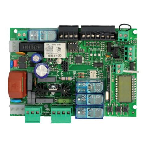
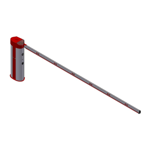
Stagnoli DAPHNE 4 User manual

Istruzioni Instructions Anleitungen Instrucciones
3
Il presente manuale è destinato solamente al personale tecnico qualificato per
l’installazione e non all’utilizzatore finale; è compito dell’installatore informare
successivamente l’utilizzatore, sulle modalità d’uso dell’automatismo, sui possibili pericoli
che ne possono derivare e sulla necessità di una manutenzione periodica.
L’installazione deve essere effettuata solo da personale qualificato e rispettando le vigenti
normative riguardanti le chiusure automatizzate.
DAPHNE è stata realizzata appositamente per gestire il controllo del passaggio di veicoli,
quindi, è vietato utilizzare il prodotto per scopi diversi da quelli previsti o in modo
improprio.
Utilizzare componenti originali. La ditta Stagnoli non si assume alcuna
responsabilità per danni dovuti all’ utilizzo di componenti non originali.
Prima di intervenire sul dispositivo, assicurarsi che l’alimentazione sia staccata.
Collegare il cavo della tensione solo a linee di alimentazione dotate di adeguate
protezioni elettriche.
Valutare con particolare attenzione i dispositivi di sicurezza da installare ed il luogo in cui
devono essere posizionati, inoltre, inserire sempre un dispositivo di arresto di emergenza
che permetta il distacco obbligato dell’alimentazione.

Istruzioni Instructions Anleitungen Instrucciones
4
Caratteristiche tecniche Daphne 4
Dati tecnici DAPHNE 4
Alimentazione 230V~ (50Hz)
Assorbimento motore. (A)
5
Alimentazione motore 24V –––––
Potenza motore max. 120W
Tempo di apertura (sec)
4
Temperatura operativa (°C)
-20 +60
Ciclo di lavoro intensivo
Livello di protezione IP
44
Peso* (Kg)
40
Lunghezza max. asta (mt)
4
Misure d’ingombro
220
1100
310
Max. 4000 mm

Istruzioni Instructions Anleitungen Instrucciones
5
Verifiche preliminari
Controllare che il terreno abbia le caratteristiche idonee a garantire una sufficiente
tenuta del plinto di cemento , in cui sarà collocata la piastra di fondazione.
Prevedere il passaggio cavi come da impianto tipo. Il passaggio cavi è situato in
posizione centrale sul fondo della barriera.
Verificare che non ci siano ostacoli nel raggio d’azione dell’asta che ne impediscano il
movimento.
Fissaggio piastra di fondazione (Fig. 2)
La barriera può essere posizionata sia a destra che a sinistra del passaggio, quindi una volta
individuata la giusta posizione procedere nel modo seguente:
Preparare una piazzola in cemento dove inserire la piastra di fondazione con i relativi
tiranti M10.
Verificare che la piastra sia perfettamente a bolla, che sia pulita sulla superficie e che i
tiranti filettati siano perpendicolari rispetto alla piastra di fondazione.
Fig. 2
Fissaggio barriera
Togliere il coperchio superiore svitando le viti (Fig. 3).
Aprire le ante, posizionare la barriera sulla piastra di fondazione facendo corrispondere i
fori con i tiranti filettati e fissare la barriera avvitando i dadi M10 sui rispettivi tiranti (Fig.4).
Fig. 3 Fig. 4

Istruzioni Instructions Anleitungen Instrucciones
6
Fissaggio asta
Fissare la staffa porta-asta, senza avvitare a fondo le viti (Fig. 5).
Verificare che sull’asta ci sia il tappo di chiusura montato su uno dei lati.
Infilare l’asta nella staffa dal lato opposto al tappo di chiusura, portarla in battuta sul
fermo posteriore e avvitare definitivamente le 4 viti M8 (Fig.6).
Fig. 5 Fig. 6
Regolazioni asta: l’apertura standard della barriera è in senso antiorario come indicato in (Fig. 7).
Fig. 7

Istruzioni Instructions Anleitungen Instrucciones
7
Per invertire il senso di apertura, spostare la molla nella posizione opposta (Fig.8) e invertire
il collegamento del motore elettrico sulla centrale di comando (Fig.9).
8APM1
9CHM1
10 LAMP
11
M1
LAMP
12
13 LC
LC
24V120W
Fig.8 Fig. 9
Bilanciare l’asta regolando il tirante filettato, l’asta deve essere in equilibrio nella posizione
di metà corsa (45°)
45°
Procedere con la programmazione seguendo le istruzioni della centrale di comando e
dopo aver effettuato la programmazione completa aggiustare le posizioni di fine corsa
dell’asta agendo sui rispettivi antivibranti in gomma.

Istruzioni Instructions Anleitungen Instrucciones
8
Manutenzione ordinaria
E’ consigliabile dopo l’installazione, effettuare dei controlli delle parti in movimento almeno ogni
6 mesi:
Verifica del bilanciamento dell’asta (se è necessario bilanciare nuovamente l’asta
regolando il tirante filettato.
Verifica del corretto allineamento dell’asta.
Ogni 500,000 manovre eseguire una revisione dei seguenti particolari:
Sostituzione dei gommini antivibranti.
Verifica del bilanciamento della molla.
Verifica del fissaggio a terra del corpo barriera, verifica del fissaggio dell’asta, verifica
del fissaggio del motoriduttore.
Controllo funzionalità ed efficienza della centrale di comando e delle relative
sicurezze e accessori.
Fissaggio accessori opzionali
1
2
Fissaggio fotocellula fissaggio selettore
Manovra manuale
La manovra manuale va eseguita solo a motore
fermo in caso di mancanza di energia elettrica.
Togliere il cilindro estraibile(1) e con l’ausilio
della chiave esagonale(2) sbloccare il
motoriduttore girando in senso antiorario.
Attenzione non eseguire la manovra manuale
se non è applicata l’asta alla barriera.
1
2

Istruzioni Instructions Anleitungen Instrucciones
9
Attention!
This manual is for qualified installers only and not for the end user. It is the installer’s job to
explain to the user how the automatism works, about possible hazards related to it and the
need for periodical maintenance.
Installation must be carried out by qualified personnel only, in compliance with current
standards concerning automatic closing mechanisms.
Daphne has been designed and made specifically to manage the access control of
vehicles. It is therefore forbidden to use the product for different reasons other than those
foreseen in this manual.
It is forbidden to use it for any other purposes or improperly.
Use original components only. Stagnoli is not liable for damages if any other components
are used.
Make absolutely certain the power is disconnected before carrying out any work on the
device.
Connect the power lead only to supply lines with adequate electrical protection.
Be particularly careful when evaluating the safety devices to install and their location.
Always install an emergency stop device that will cut power off in the case of necessity

Istruzioni Instructions Anleitungen Instrucciones
10
Tecnical Details
Tecnical Details DAPHNE 4
Power Supply 230V~ (50Hz)
Current absorbed Motor (A)
5
Motor Power Supply 24V –––––
Maximum Power Max 120W
Opening Time (sec) 4
Operating Temperature (°C) -20 +60
Duty Cycle intensive
IP Protection 44
Weight (Kg) 40
Max. Length of arm (mt) 4
Dimensions
220
1100
310
Max. 4000 mm

Istruzioni Instructions Anleitungen Instrucciones
11
Preliminary Checks
Make sure that the ground is ideal for holding the cement base, in which the foundation
plate will be mounted.
Make sure to foresee the passage of the cables as in the ideal set-up. The cable passage
is situated in a central position on the back of the barrier.
Make sure that there are no obstacles in the way of the arm’s radius that could stop it’s
movement.
Fixing of the foundation plate (Fig. 2)
The barrier can be positioned either to the right or to the left of the passage. Therefore, once
decided the correct position proceed to the following steps:
Prepare a cement base where you can insert the foundation plate with the relative rods.
Make sure that the plate is perfectly flat, that it’s surface is perfectly clean and that the
rods are precisely perpendicular to the ground.
Fig. 2
Fixing the barrier
Take the top cover off by unscrewing the screws (Fig. 3).
Open the barrier wings, position the barrier on the foundation plate making sure that the
lower holes correspond to the screwable rods and screw everything in place with the M10
nuts. (Fig.4).
Fig. 3 Fig. 4

Istruzioni Instructions Anleitungen Instrucciones
12
Fixing the arm
Fix the arm-holding bracket into place, loosely tightening the screws (Fig. 5).
Make sure that the barrier arm is covered with it’s lid on one of the 2 sides.
Slide the barrier arm into the bracket from the opposite side of it’s lid, slide it along until it
jams into place and screw in tightly the M8 screws that you had left loosely tightened
beforehand (Fig.6).
Fig. 5 Fig. 6
Adjusting the arm: the standard opening of the barrier is in an anticlockwise direction
as in (Fig. 7).
Fig. 7

Istruzioni Instructions Anleitungen Instrucciones
13
To invert the opening direction of the arm, move the spring to the opposite position (Fig.8)
and invert the connection of the electric motor to the control panel (Fig.9).
8APM1
9CHM1
10 LAMP
11
M1
LAMP
12
13 LC
LC
24V120W
Fig.8 Fig. 9
Balance the barrier’s arm adjusting the screwable rods. The arm must be in equilibrium in
the half way position (45°).
45°
Proceed with the programming of the control panel following the specific electrical
instructions and then regulate the position of the arm’s limit switches, lowering or raising
the relative rubber antivibration drums

Istruzioni Instructions Anleitungen Instrucciones
14
Ordinary Maintenance
It is advisable, after installation, to carry out checks on the moving parts, at least every 6 months:
Check the balance of the arm ( if necessary rebalance the arm adjusting the screwable
rods).
Check the correct alignment of the arm.
Every 500,000 manoeuvres carry out a revision of the following parts.
Replace the rubber antivibration drums
Check that the spring is balanced
Check that the body of the barrier is securely grounded, check that the arm is still tightly
attached and check that the motor is still securely fixed.
Check the relative functionality of the control panel and the safety accessories.
Fixing optional accessories
1
2
Fixing the photocell Fixing the digital or key pad
Manual Manoeuvre
The manual manoeuvring of the arm should
only be carried out when the motor has
stopped due to a cut in the power supply
Pull off the self releasing cylinder (1) and with
the Alan key (2) unblock the motor turning
the key in an anticlockwise direction.
Warning! Do not carry out the manual
manoeuvring if the arm is not fixed to the
motor.
1
2

Istruzioni Instructions Anleitungen Instrucciones
15
Attention!
Le présent manuel est destiné uniquement au personel technique qualifié dans le
domaine d’installation et non à l’utilisateur final; c’est la responsabilité de
l’installateur de faire informer succéssivement l’utilisateur de toutes les modalités
de l’usage de l’automate, des dangers possibles qui en puissent ensuite dériver et
de même de la nécessité d’une manutention périodique.
L’installation doit être effectuer uniquement par le personnel qualifié et en
respectant les instructions normatives concernant les fermetures automatiques.
DAPHNE a été réalisée expressément pour gérer le contrôle du passage des
véhicules, il est défendu alors d’utiliser le produit pour les buts divers des ceux
prévus ou du mode impropre.
Utiliser pièces originales. L’entreprise Stagnoli non assume aucune responsabilité
pour les dommages provoqués par l’utilisage des components non originaux.
Avant d’intervenir sur le dispositif, il faut s’assurer que l’alimentation ait été
déchargée.
Faire connecter le câble de la tension uniquement aux lignes d’alimentation
dotées d’ adequates protections électriques.
Valoriser avec l’attention particulière les dispositifs de sécurité pour installer et le
lieu où ils doivent être positionnés, de plus, insérer toujours un dispositif d’arrêt au
cas du danger qui permet le débranchement obbligé de l’alimentation.

Istruzioni Instructions Anleitungen Instrucciones
16
Caractéristiques techniques
Données techniques DAPHNE 4
Alimentation 230V~ (50Hz)
Absorption moteur (A) 5
Alimentation moteu
r
24V –––––
Puissance moteur max. 120W
Temps d’ouverture (sec)
4
Température opérationnelle(°C)
-20 +60
Cycle de travail intensif
Niveau de protection IP
44
Poids* (Kg)
40
Longueur max. de barre (m)
4
Mésures d’encombrement
220
1100
310
Max. 4000 mm

Istruzioni Instructions Anleitungen Instrucciones
17
Vérifications préliminaires
Contrôler que le terrain ait les caractéristiques similaires et garantir une suffisante
étanchéité de la base du ciment dans laquelle la plaque de fondation va être plaçée.
Prévoir le passage pour les câbles comme dans le cas de dispositif type. Le passage pour
les câbles est situé en position centrale sur le fond de la barrière.
Vérifier qu’il n yait pas des obstacles en rayon d’action de la barre qui pourraient entraver
le mouvement.
Fixation de la plaque de fondation (Fig. 2)
La barrière peut être positionnée ou à droit ou à gauche du passage, une fois alors la position
juste individualisée on peut procéder de la manière suivante:
Préparer una plate-forme de ciment où il faut insérer la plaque de fondation avec les tirants
relatifs M10.
Vérifier que la plaque soit parfaitement nettoyée sur la surface et que les tirants rayés soient
perpendiculaires par rapport à la plaque de fondation.
Fig. 2
Fixation de la barrière
Retirer la couverture supérieure dévissant les vis (Fig. 3).
Ouvrire les antes, positionner la barrière sur la pplaque de fondation faisant correspondre les
orifices des tirants rayés et faire fixer la barrière vissant écrous M10 sur les tirants relatifs (Fig.4).
Fig. 3 Fig. 4

Istruzioni Instructions Anleitungen Instrucciones
18
Fixation de la barre
Faire fixer le support porteur-barre, sans visser à fond les vis (Fig. 5).
Vérifier que sur la barre se trouve le tampon de fermeture monté sur un des côtés.
Introduire la barre dans le support du côté opposé au tampon de fermeture, la faire
porter en battement sur la pince postérieure et visser définitivement les 4 vis M8 (Fig.6).
Fig. 5 Fig. 6
Regulation de la barre : l’ouverture standard de la barrière est au sens contraire au mouvement
de l’horloge comme indiqué en (Fig. 7).
Fig. 7

Istruzioni Instructions Anleitungen Instrucciones
19
Pour invertir le sens d’ouverture, déplacer le ressort en position opposée (Fig.8) et faire
invertir la connexion du moteur électrique sur la centrale de commando (Fig.9).
8APM1
9CHM1
10 LAMP
11
M1
LAMP
12
13 LC
LC
24V120W
Fig. 8 Fig. 9
Équilibrer la barre regulant le tirant rayé, la barre doit être en équilibre en position de demi
course (45°)
45°
Procéder avec la programmation respectant les instructions de la centrale de
commande et après avoir effectué la programmation complète ajuster les positions de fin
de course de la barre agissant sur les relatives pièces antivibratiles en gomme.

Istruzioni Instructions Anleitungen Instrucciones
20
Manutention ordinaire
Après l’installation, il est suggéré d’effectuer des contrôles des pièces en mouvement au moins
tous les 6 mois:
Vérifier l’équilibre de la barre (si nécessaire èquilibrer de nouveau la barre regulant le
tirant rayé)
Vérifier l’alignement correct de la barre.
Tous les 500,000 manoeuvres effectuées il faut conduire une révision des suivantes pièces
particulières:
Remplacement des gommes antivibratiles.
Vérification de l’équilibre du ressort.
Vérification de la fixation à terre du corps de la barrière, vérification de la fixation de la
barre, vérification de la fixation du motoréducteur.
Contrôle de fonctionnalité et de efficacité de la centrale de commande et de la sécurité
relative et accessoires.
Fixation accessories:
1
2
Fixation de la photocellule (optionelle) Fixation sélecteur (optionelle)
Manœuvre manuelle
La manoeuvre manuelle sera exécutée
uniquement lors le moteur arrêté au cas du
manque d’énergie électrique.
Retirer le cylindre extrayable(1) et avec l’auxiliare
de la clé héxagonale(2) débloquer le
motoréducteur tournant au sens contraire au
movement de l’horloge.
Attention ! ne pas exécuter la manoeuvre
manuelle sans que la barre soit appliquée à la
barrière.
1
2
Other manuals for DAPHNE 4
1
Table of contents
Languages:
Other Stagnoli Control System manuals
Popular Control System manuals by other brands
Anilam
Anilam 4200T Programming and operations manual

Rain Bird
Rain Bird ESP-LXD Installation & troubleshooting guide

Pentatech
Pentatech GA50 instruction manual

Cleveland
Cleveland HA-DE-CC Specifications
Mitsubishi Electric
Mitsubishi Electric E70 Series instruction manual
Extron electronics
Extron electronics TouchLink TLP Pro 525C Series user guide


