LenelS2 LNL-1200 Series User manual

Output Control Module LNL-1200 Series 3 Quick Reference
for rev. D (SN > 2,000,000)
For detailed information, refer to the Hardware Installation Guide, DOC-600.
© 2020 Carrier. All Rights Reserved. LenelS2 is a part of Carrier. 1QR50L-1032E — revision 3.004
The LNL-1200 Board
The LNL-1200 processor provides a solution to the host system integrator
for output control. The controller has 16 form-C contact relays for load
switching. Additionally, two (2) digital inputs are provided for tamper and
power fault status monitoring. The processor requires 12 to 24 VDC for
power.
Supplying Power to the LNL-1200
The LNL-1200 requires 12 to 24 VDC for power on TB11. Locate power
source as close to the unit as possible. Connect power with a minimum of 18
AWG wires.
Observe POLARITY on VIN!
The VOUT terminal on TB11 is the same as VIN.
Communication Wiring
The LNL-1200 communicates to a controller via a 2-wire RS-485 interface.
The interface allows multi-drop communication on a single bus of up to
4000 feet (1219 m). Use twisted pair (minimum 24 AWG) with shield for
the communication line. See Specifications section.
Install RS-485 termination jumper, J1, on the interface boards at each end of
the communication line only.
2-Wire RS-485
The LNL-1200 Board Callouts
Callout Description
1Outputs
2 Tamper and power monitor inputs
3 Serial I/O communication port, RS-485
4 Power in 12 to 24 VDC
5 Eight (8) mounting holes (Ø0.156 [Ø4.0])
6 Earth ground (connection not required)
7 Status LEDs
8Outputs
9 DIP switches
10 Relay status LEDs
.25 [6.35]
.50 [12.70]
NC
C
NO
NC
C
NO
OUT 8
OUT 7
NO
C
NC
NO
C
NC
OUT 6
OUT 5
NO
C
NC
NO
C
NC
OUT 4
OUT 3
NO
C
NC
NO
C
NC
OUT 2
OUT 1
NO
C
NC
NO
C
NC
OUT 9
OUT 10
C
NO
NC
C
NO
NC
OUT 11
OUT 12
NC
C
OUT 13
NO
NC
OUT 14
NO
C
OUT 16
NO
C
OUT 115
NC
C
NO
NC
TR+
GND
TR-
RS-485
GND
VIN
GND
BA
CT
GND
VOUT
TB10
TB9
TB11
J1
S112345678
A
B
CT
BA
TB4
TB3
TB2
TB1 TB5
TB6
TB7
TB8
1234
S2
K1 K2 K3 K4 K5 K6 K7 K8
K9 K10 K11 K12 K13 K14 K15 K16
1243 512
9
7
6813 14
10 11 15 16
1
2
3
5
7
8
10
9
4
6
6.00 [152.40]
5.50 [139.70]
8.00 [2.03.20]
3.00 [76.20] 2.00 [50.80]
2.00 [50.80]
Communication Wiring Callouts
Callout Description
1 To all other devices on the bus
2 To all other devices on the bus
ONLY 2-WIRE RS-485 IS SUPPORTED.
VIN
GND
+
-
12 to 24 VDC
TB11
VOUT
TR+
TR -
GND
TB10
1
2

Output Control Module LNL-1200 Series 3 Quick Reference
© 2020 Carrier. All Rights Reserved. LenelS2 is a part of Carrier. 2 QR50L-1032E — revision 3.004
Inputs for Cabinet Tamper/Power Fault
Input CT and input BAare used for monitoring cabinet tamper and power
failure with normally closed contacts. These two (2) inputs are for contact
closure monitoring only, and do not use EOL resistor(s). If these inputs are
not used, install a short piece of wire at the input to indicate a safe condition.
Output Relay Wiring
16 Form-C contact relays are provided for controlling door strikes or other
devices. Load switching can cause abnormal contact wear and premature
contact failure. Switching of inductive loads (strike) also causes EMI
(electromagnetic interference) which may interfere with normal operation of
other equipment. To minimize premature contact failure and to increase
system reliability, a contact protection circuit must be used. The following
two (2) circuits are recommended. Locate the protection circuit as close to
the load as possible (within 12 inches [30 cm]), as the effectiveness of the
circuit will decrease if it is located farther away.
Use sufficiently large gauge of wires for the load current to avoid voltage
loss.
Diode Selection: Diode current rating: 1x strike current. Diode breakdown
voltage: 4x strike voltage. For 12 VDC or 24 VDC strike, diode 1N4002
(100V/1A) typical.
DIP Switch and Jumper Usage
Switches 1 to 5 select the device address. Switches 6 and 7 select the
communication baud rate. Switch 8 enables encrypted communication.All
other configuration settings are set via the host software.
Device Address
Inputs for Cabinet Tamper/Power Fault Callouts
Callout Description
1 Cabinet tamper
2 Power fault
Output Relay Wiring Callouts
Callout Description
1DCstrike
2 Diode
3 Fuse
4 To DC power source
CT
GND
BA
GND
TB9
1
2
NC
C
NO
NC
C
NO
+-
4
2
1
3
DIP switch(es) Used to configure:
1, 2, 3, 4, 5 Device communication address (0-31)
6, 7 Communication baud rate
8Downstream encryption (available with OnGuard®2009
or later)
Address DIP switch
5: 4: 3: 2: 1:
0 off off off off off
1 off off off off ON
2 off off off ON off
3 off off off ON ON
4 off off ON off off
5offoffONoffON
6offoffONONoff
7 off off ON ON ON
8 off ON off off off
9 off ON off off ON
10 off ON off ON off
11 off ON off ON ON
12 off ONONoff off
13 off ONONoff ON
14 off ONONONoff
15 off ONONONON
16 ON off off off off
17 ON off off off ON
18 ON off off ON off
19 ON off off ON ON
20 ON off ON off off
21 ON off ON off ON
22 ON off ON ON off
23 ON off ON ON ON
24 ON ON off off off
25 ON ON off off ON

Output Control Module LNL-1200 Series 3 Quick Reference
© 2020 Carrier. All Rights Reserved. LenelS2 is a part of Carrier. 3 QR50L-1032E — revision 3.004
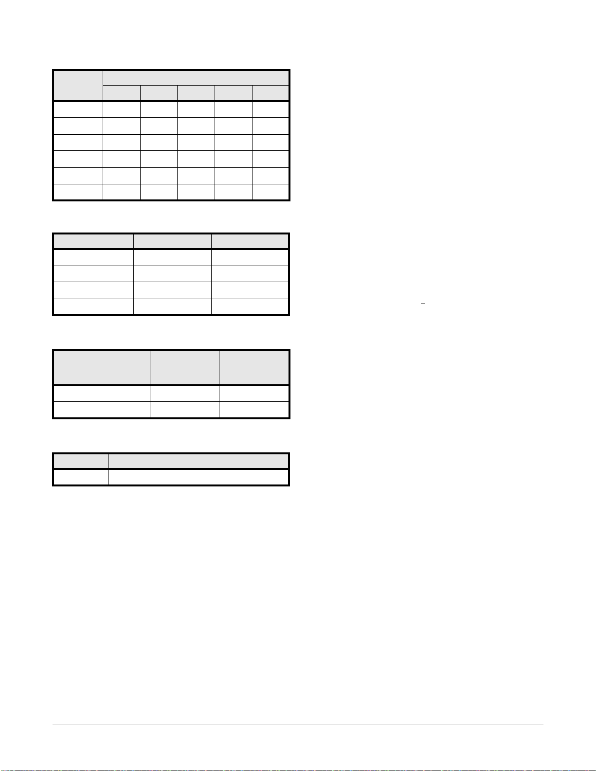
Communication Baud Rate
Bus Encryption
Jumpers
All other jumpers are factory use, only.
Status LEDs
Power-up:All LEDs OFF.
Initialization: Once power is applied, initialization of the module begins.
When initialization is completed, LEDs A. B, CT, and BA are briefly
sequenced ON then OFF.
Run time: After the above sequence, the LEDs have the following
meanings:
A LED: Heartbeat and On-Line Status:
• Off-line: 1 second rate, 20% ON
• On-line:
- Non-encrypted communication: 1 second rate, 80% ON
- Encrypted communication: 0.1 sec ON, 0.1 sec OFF, 0.1 sec
ON, 0.1 sec OFF, 0.1 sec ON, 0.1 sec OFF, 0.1 sec ON, 0.3 sec
OFF
A LED: Error Indication:
Waiting for application firmware to be downloaded: 0.1 sec ON, 0.1 sec
OFF.
B LED: Serial I/O Communication Port Status:
Indicates communication activity on the serial I/O communication port:
CT: Cabinet Tamper
BA: Power Fault
LED 1 through 16: Illuminate when output relay OUT 1 (K1), OUT 2 (K2)
is energized and so on.
Specifications
The LNL-1200 is for use in low voltage, class 2 circuit, only. These
specifications are subject to change without notice.
• Primary power: 12 to 24 VDC + 10%, 1100 mA maximum
• Relay contacts: 16 Form-C:
- Normally Open (NO) contact: 5 A @ 30 VDC resistive
- Normally Closed (NC) contact: 3 A @ 30 VDC resistive
• Inputs: 2 unsupervised, dedicated for cabinet tamper and UPS fault
monitoring
• Communication: RS-485, 2-wire: 9600, 19200, 38400, or 115200 bps
• Cable requirements:
- Power: 1 twisted pair, 18AWG
- RS-485: 24 AWG, 120 ohm impedance, twisted pair with drain
wire and shield, 4000 feet (1219 m) maximum
- Inputs:1 twisted pair, 30 ohms maximum
- Outputs: as required for the load
• Mechanical:
- Dimension: 6 x 8 x 1 in. (152 x 203 x 25.4 mm)
- Weight: 14 oz. (400 g) nominal
• Environmental:
- Temperature: -55 to 85° C storage, 0 to +70°C operating
- Humidity: 5 to 95% RHNC
UL 294, 7th edition Performance Levels:
Note: Outputs are Power limited/class 2 when powered by external
power limited/class 2 power supply model LNL-AL400ULX or
LNL-AL600ULX-4CB6.
26 ON ON off ON off
27 ON ON off ON ON
28 ON ON ON off off
29 ON ON ON off ON
30 ON ON ON ON off
31 ON ON ON ON ON
Baud rate DIP switch 6: DIP switch 7:
38,400 bps ON ON
19,200 bps off ON
9600 bps ON off
115,200 bps off off
Bus communications DIP switch 8:
(OnGuard 2009
or later)
DIP switch 8:
(prior to
OnGuard 2009)
Encryption is not required off Normal operation
Encryption is required ON Not allowed
Jumper Description
J1 RS-485 termination; install in first and last units, only
Address DIP switch
5: 4: 3: 2: 1:
Feature Level
Standby Power I
Endurance IV
Line Security I
Destructive Attack I

Output Control Module LNL-1200 Series 3 Quick Reference
© 2020 Carrier. All Rights Reserved. LenelS2 is a part of Carrier. 4 QR50L-1032E — revision 3.004
Regulatory Information
FCC Compliance
This device complies with part 15 of the FCC Rules. Operation is subject to
the following two conditions: (1) This device may not cause harmful
interference, and (2) this device must accept any interference received,
including interference that may cause undesired operation.
Liability
It is expressly understood and agreed that the interface should only be used
to control exits from areas where an alternative method for exit is available.
This product is not intended for, nor is rated for operation in life-critical
control applications. LenelS2 is not liable under any circumstances for loss
or damage caused by or partially caused by the misapplication or
malfunction of the product. LenelS2’s liability does not extend beyond the
purchase price of the product.
Certifications
For certification information, refer to the hardware documentation for the
host application.
Product Warnings and Disclaimers
THESE PRODUCTS ARE INTENDED FOR SALE TO, AND
INSTALLATION BY, AN EXPERIENCED SECURITY
PROFESSIONAL. LENELS2 CANNOT PROVIDE ANY ASSURANCE
THAT ANY PERSON OR ENTITY BUYING ITS PRODUCTS,
INCLUDING ANY “AUTHORIZED DEALER”, IS PROPERLY
TRAINED OR EXPERIENCED TO CORRECTLY INSTALL SECURITY
RELATED PRODUCTS.
For more information on warranty disclaimers and product safety
information, please check https://firesecurityproducts.com/en/policy/
product-warning or scan the following code: