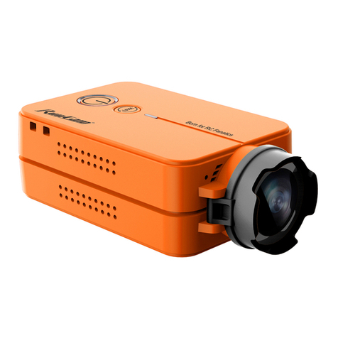
Jeasun HD96 User manual

All-in-one type Full HD sports camera with 2.0” screen


1
PREFACE
Thank you for purchasing the high resolution digital camcorder. The
camcorder is a small, all-in-one design that is convenient for you to record activities
anytime and anywhere. With the high speed dynamic photograph function, it can
clearly record any activity, and let you share the experience with anybody.
Please read this manual carefully to ensure you understand it before using this
product. Please also keep this manual safe for future reference.
PRODUCT ASSURANCE
This product has authoritative CE, RoHS & FCC certication to assure customer
safety when using it.
PRODUCT OVERVIEW
The camcorder has world leading digital video/photography/audio storage,
high-speed HDMI video transmission and other functions, as well as a number
of invention patents & technical patents.
Getting Started

Getting Started
19 20 21 22
2
1. 110°lens
2. Horizontal laser light
3. Camera shutter
4. [⊙]Press and Hold for 2 seconds to
power on or power o the Cam
5. Recording key
6. Turn on or turn o the horizontal laser light
7. 200°rotating lens
8. Recording indicator
9. External MIC interface
10. Wired-Remote jack、USB jack、AV-OUT jack
11. 1/4 Screw Thread
12. Lanyards orice
13. Power indicator
PRODUCT STRUCTURE
14. Locking key of rear cover
15. Internal MIC
16. Loudspeaker
17. 2-inch LCD Screen
18. Playback integrated key
19. Battery Holder
20. HDMI output jack
21. Micro-SD Holder
22. Screen Cover
MAIN UNIT

HDMI OUT
CARD/BATT
OPEN
▲
HDMI OUT
CARD/BATT
OPEN
▲
▲
3
Installing the Battery
1. Slide the lock on the rear cover and it will automatically open. (Refer to picture1)
2. Follow the instructions. Insert the battery with the correct Polarity (+/-). (Refer to picture2)
3. Push the rear cover closed. (Refer to picture3)
NOTE: IF YOU DO NOT INTENT TO USE THE PRODUCT FOR
A LONG TIME, PLEASE REMOVE THE BATTERY. BATTERIES
CONTAIN CHEMICAL SUBSTANCES SO THEY SHOULD BE
HANDLED AND DISPOSED OF CORRECTLY.
Installing the Micro-SD card
1: Slide the lock on the rear cover and it will automatically open. (Refer to picture4)
2: Follow the instructions. Insert the SD card in the correct direction. (Refer to picture 5)
3: Push the back cover to the closed position. (Please refer to picture6)
NOTE: THE CAMECORDER REQUIRES A CLASS 4 OR ABOVE SD
CARD TO OPERATE CORRECTLY. MOST FAULTS WITH
OPERATING CAMERAS ARE BECAUSE A CHEAP SD CARD
IS USED. CHOOSE ADDITIONAL SD CARD WITH CARE.
Picture1
Picture2 Picture3
Picture4
Picture5 Picture6
Basic Operations
Basic Operations

Basic Operations
REC
4
Picture1
Picture2 Picture3
Recording Instructions
1.Press [⊙] key and hold for 2 seconds to power up the camera.
2. Adjust the lens to the proper angle.
a) Face a blank surface and press [⊙] to turn on the lasers ( The lasers will disappear in 15
seconds). The laser can be turned on or o at any time with the laser light button.
b) Check whether the laser light is horizontally aligned. If not, rotate the lens until it is in
the horizontal state. (Refer to picture1)
WARNING: DO NOT DIRECT THE LASER LIGHT INTO ANYBODY’S EYES
The indicator light glows green to indicate standby mode.
3. Start / stop recording
a) Slide the recording switch forward. The recording indicator ( red ) turns on and ashes
while camera beeps (These audio beeps can be turned o in the menu), and camera is
recording . (Refer to picture2)
b) To stop recording, slide the switch backwards, the camera beeps and the indicator light
turns green indicating standby mode. (Refer to picture3)
* With the LCD screen constantly on the battery will only last for approximately 30 minutes.
By pressing the LCD button the screen will turn o and then the battery will last for 2-3
hours. By pressing the LCD button for 2 seconds the camera will completely turn o.
* The LCD screen will shut o automatically 30 seconds after the camera starts recording,
and the LCD screen will also shut o automatically 60 seconds when in standby mode if
no keys pressed. It allows more time to the user for tuning the camera. But the LCD
won’t shut o during Playback mode.
Basic Operations

Basic Operations
DIGITAL
REC
DIGITAL
5
Picture1
Picture2
Start / stop Recording Via Wired Remote
Press [⊙] key ( hold for 2 seconds ) to power up the camera.
1. Connect wired remote to the DIGITAL interface of camera (Refer to picture 1)
2: Press [REC] key on the wired remote to start recording, recording indicator ( red ) turns
on and ashes when it is recording.
3. During recording, press [REC] key on wired remote again to stop, and recording indicator
turns o when camera stops recording.
Start / stop recording automatically by power-on wired remote.
1. Connect one end of power-on wired remote to the DIGITAL interface on the camera.
(Refer to picture 1)
2: Connect the other end of power-on wired remote to a 5V power source. (Refer to picture 2)
As long as the DC5V input is detected by camera it will start recording automatically.
During recording, if DC5V is stopped being detected by camera, then it will stop recording
automatically.
NOTE: 1. YOU MUST HAVE A WELL CHARGED BATTERY INSERTED IN TO THE CAMERA FOR THE AUTO
5V INPUT AUTO RECORD FUNCTION TO WORK CORRECTLY.
2. IN STANDBY MODE OR RECORDING MODE YOU CAN ENTER INTO REAL-TIME PREVIEW
IMAGES AFTER OPENING THE LCD.
3. IN STANDBY MODE OR RECORDING MODE YOU CAN ENTER INTO REAL-TIME PREVIEW BY
CONNECTING THE CAMERA TO OTHER DISPLAY DEVICES.
4. IN RECORDING MODE YOU CAN CONNECT AN EXTERNAL MIC TO ENHANCE AUDIO
RECORDING , AND EXTERNAL MIC AND INTERNAL MIC AUDIO RECORDING CAN BE MIXED.
Basic Operations

Basic Operations
MOVIE
100-0014
6
Picture1
Picture2 Picture3
Picture Shooting Instructions
In standby mode , press [ ] key to take photos. (Refer to picture1)
Picture Resolution: 5 mega pixels
Picture Size: 2560 x 1920
Playback Instructions
1. Playback on the camera
a)Press and push the screen cover backwards to open it. (Refer to picture1)
b)Gently press [LCD] key , and the screen will come on.
c)Press [MODE] to switch until you see the Play Mode, the screen shows 6 video les per
page in grid form.
d)Press [+][-] to choose which video to play, the video will be highlighted with yellow
borders, press [ ‖]to start recording, and press again to stop.
e)When playing video, user can short press [+][-] to turn up or turn down the volume.
f)When playing video, user can Long press [+][-] to Fast forward or reverse at X2/X4/X8.
g)Press[MODE]to stop playback, and return to the video les listing.
h)Gently press [LCD]key to turn the LCD screen o.
i)Push the rear cover back on to protect the screen when not in use.
Push the screen cover by this way.
Basic Operations

A
BC
D
E
7
Mount Installation
Mount Installation
MOUNTS
A .Cradle: with two 1/4 tripod threads tted for use with other mounts as shown
below, this camera can be widely used with any equipment and any application.
B. Goggle Strap Mount: can be xed on to your goggle strap and any other elastic
band or strap.
C. Flat Mount: With a high performance, waterproof and heat-resistant 3M sticker
at the back, it is ideal for at, non-porous surfaces.
D. Bar Mount: with 3 sizes of rubber, the camera can be mounted on to the tubes
of mountain bike handle bars, roll bar cages etc.
E: Vented Helmet Mount, with the Velcro strap is ideal for mounting the camera to
various styles of vented helmets.

Main Mount
Bar Mount
Note: 1) Other mounts require this main mount for installing
2) Tripod thread on device for installing on surface
Main Mount
Bar Mount
3 × Rubber Insert
1 × Hand screw
Step 1
to adapt dierent bike bar
Step 2
Step 3
Step 4
Step 1 Step 2
Note: please choose the proper rubber insert of dierent thicknesses.
8
AV OUT
DIGITAL
100°
100°
MIC -IN
AV OU T
DIGITAL
Bike bar
Ruber insert
Mount Installation

Step 1 Step 2
9
Vented Helmet Mount
Note: 1) Other mounts require this main mount for installing
2) Tripod thread on device for installing on surface
3 × Flat Mount
1 × Elastic strap
Main Mount
Flat Mount
Vented helmet
Vented helmet mount
Mount
Step 1: push at mount to main mount
Step 2: peel o the sticker
Step 3: paste the camera to your helmet
Flat Mount
12
Helmet
3
Mount Installation

Goggle Strap Mount
Strong Suction Cup
10
HDMI OUT
CARD/BATT
OPE N
AV OUT
DIGITAL
Goggle Strap Mount
Choice A Choice B
Main Mount
Goggle
Step 1: install mount to goggle
Step 2: push the device with main mount to the mount
Screw the suction cup to
the tripod thread in the device.
Screw the suction cup to
the tripod thread in the main mount.
1
2
Mount Installation

Mini Tripod
Lanyard Rope
Step 1 Step 2 Step 3
11
HDM I OUT
CARD/BATT
OPE N
AV OUT
DIGITAL
MIC-IN
AV OU T
DIGITAL
100°
MIC -IN
AV OUT
DIGITA L
100°
Choice A
Screen Cover
Screw the suction cup to
the tripod thread in the device.
Then when you are recording, the screen cover will not be lost.
Choice B
Screw the suction cup to
the tripod thread in the main mount.
Mount Installation

Waterproof Case
Step 1
Step 3 Step 4
Step 2
Note: 1) Before load the device into the waterproof case,
please slide switch of recording, and note the direction of device.
Note: After load device into waterproof case, please lock it
Note: Press the button of power to start recording
12
REC
3
4
1
2
7
6
5
REC
LCD
Mount Installation

13
2. Connect to other TV/Display devices to playback.
a)Connect one end of AV-out cable to the DIGITAL interface on the base of the camera, and
connect the other end of AV-out cable to your TV or other display device.( Refer to picture1)
b)Turn on the TV or display device, and enter into the AV-in mode.
c)Press[MODE]to switch to Play Mode, the screen shows 6 video les per page in grid form.
d)Press [+][-] to choose which video to play, the video will be highlighted with yellow borders,
press [ ‖] to start recording, and press again to stop.
e)When playing video, user can short press [+][-] to turn up or turn down the volume.
f)When playing video, user can Long press [+][-] to Fast forward or reverse at X2/X4/X8.
g)Press[MODE]to stop playback, and return to the video les list.
h)Gently press [LCD]key, and LCD Screen is o.
i)Push the screen cover back on to protect the screen when not in use.
DIGITAL
DIGITAL
11
Picture1
Picture2
OPERATING INSTRUCTIONS
3.Playback on a PC
Connect AV-out cable to digital interface of camera, and connect the other end of AV-out
cable to USB jack of PC. (Refer to picture2)
Mount Installation

AV OUT
MIC-IN
HDMI OUT HDMI IN
HDMI
HDMI
14
Picture1
Picture2
Picture3
OUTPUT CONNECTION
Connect to external MIC
Connect MIC device to camera for capturing higher quality audio.
Connect to HD TV via HDMI
Connect HDMI cable to HDMI interface on the camera and HDMI interface of TV. The LCD
will turn o automatically when connected to TV. (Refer to picture2)
Connect to TV via AVOUT
Connect the AV cable to AV-OUT jack of camera and AVIN jack of TV. The LCD will turn
o automatically when connect to TV. (Refer to picture3)

USB
DC IN
15
Picture1
Picture2
Connect to PC via USB
Connect USB to the Digital interface of camera and USB port on the PC. (Refer to picture1)
Connect to power source
1. Connect the power line to DIGITAL interface of camera, power light (Red) is on when
it is connected.
2. When the camera is o, connect the power line to camera, it will supply power for the
camera. Power light (Red) is o when fully charged.
OUTPUT CONNECTION

16
Setting Operational Approach
Press[MODE] to switch into system function settings mode.
1: Press [▲][▼] key to shift the yellow cursor, choose the setting function, press [OK]key
to set up.
2. Press [▲][▼] key to choose the needed function, press[OK]again.
Press[MODE]to switch into system function settings mode.
3. After Pressing[OK]key it will automatically return to the main menu.
Resolution Setting
Set up the required recording resolution:
FULL HD = 1920x1080 30fps 1080P30 = 1920x1440 30fps
720P25 = 1280x720 25fps 720P30 = 1280x720 50fps
720P30 = 1280x720 30fps 720P60 = 1280x720 60fps
720P60 = 1280x720 60fps WVGA30 = 848x480 60fps
WVGA60 = 848x480 60fps
The higher resolution you choose the less video you can t on your SD card.
Quality Setting
H: High L: Low M: Medium
The higher the quality setting you choose the less video you will be able to store on your
SD card.
Video Rotation Setting
STANDARD: Choose this setting when the camera is installed in the normal position.
INVERTED: Choose this setting when the camera is installed in the inverted position.
Using this setting you can invert the image being recorded. This is useful if you wish to
lm with the camera in the upside down position. The image will be ipped the right
way up using this setting.
SYSTEM SETTINGS

17
Record Mode Setting
NTSC PAL
When using in dierent countries, choose the TV system according to local standard. The
image will be ickeringly if the TV system is set incorrectly.
External MIC VOL Setting
The volume of external MIC or audio equipment can be set, and there are 7 grades that
can be selected. It will be stereo when it is used with the external MIC.
Internal MIC VOL Setting
The volume of internal MIC can be set and there are 7 grades to be selected, there will be
stereo when it is used with the external MIC, defaults to right channel.
Record Overwrite Setting
When set as the RECORD OVERWRITE mode, the video will default to 5 minute per le.
When the card is full it will start overwriting the earliest recorded les.
Motion Detection Setting
Setting as below:
NO: No start MOTION DETECTION function
1 MIN: Start MOTION DETECTION function, it will delay 1 minute to stop recording after
the object leaves the shooting range.
3 MINS: Start MOTION DETECTION function, it will delay 3 minutes to stop recording after
the object leaves the shooting range.
5 MINS: Start MOTION DETECTION function, it will delay 5 minutes to stop recording after
the object leaves the shooting range.
When set in the MOTION DETECTION mode, the camera will automatically start recording
when it detects any kind of movement in its lming range. When the motion stops, the
camera will automatically stop recording again.
Time Stamp Setting
OFF: No time stamp
DATE: DATE only
TIME: TIME only
DATE/TIME: both DATE/TIME
With this setting, the current time will be stamped on the video and the recording time
can be seen during playback.
SYSTEM SETTINGS

18
TV Type Setting
PAL NTSC
Choose the correct video output system when connecting AVOUT to TV. The image on the
TV will be ickering if the TV system is incorrect
Time Setup Setting
There is year / month / day / hour / minute to set up on the camera.
Beep Sound Setting
When you operate the camera, the key tone can be set to on or o.
Format Setting
Format the micro SD Card.
Note: ALL FILES IN THE MICRO SD WILL BE DELETED AND WILL BE UNRECOVERABLE AFTER
FORMATTING. WE SUGGEST YOU FORMAT YOUR MEMORY CARD ON A REGULAR BASIS.
SHOULD YOU HAVE A PROBLEM WITH YOUR CAMERA, FORMATTING THE MEMORY CARD
WILL QUITE OFTEN SOLVE THE ISSUE.
Language Setting
ENGLISH
FRENCH
Select the needed language
●All specications above are based on the testing standard of MICAMCORDER.
●Appearance and all specications are subject to change without prior notice.
●Color of product shown in the user manual maybe dierent from that included in the
package. The Pictures are for your reference only.
SYSTEM SETTINGS
Table of contents
Other Jeasun Action Camera manuals
