Jefa Steering Systems DU-TS24-24 Service manual

Test data and installation instructions 300 Nm
transmission autopilot drive 24 volts type
DU-TSxx-24.
(version 1.4)
Test data:
Customer: …………… Test Engineer: …………..
Date: ………………… Serial number: …………..
Output torque 300 Nm: type DU-TS24-24 – 8 revolutions/minute
Motor Voltage: 24 Volts type DU-TS18-24 – 6.5 revolutions/minute
Clutch voltage: 24 Volts type DU-TS10-24 – 3 revolutions/minute
Insulation test:
Transmission drive type TS250 installation guide version 1.4 page 1 of 4
Electrical Connections: This illustration shows the minimal
components for a working autopilot
configuration. Jefa autopilot drives
work together with all mayor
autopilot electronics. The
connection of the Jefa autopilot
drive to the autopilot junction box
is quite simple. The two 1.5 mm²
red and black wires have to be
connected to the plus and minus of
the autopilot clutch line. This will
make sure that when the autopilot
user engages the autopilot on the
control screen, the clutch will
engage and allow the autopilot
motor to drive the steering system.
The two 4 mm² red and black wires
have to be connected to the
autopilot drive output connection.
autopilot control head
rudder feedback unit
autopilot junction box
fluxgate compass
clutch
output drive
output
1,5 mm2 4 mm2
to battery
drive unit
DU-TS24-18 performance table: (in combination with the 1:7 reduction box RG10-70)
rudder torque
full rudder
(KgM)
rudder torque
midships
(KgM)
power
usage
(amps)
rudder rotation
per second
(degrees/sec.)
time for
72° rudder
(sec)
0 0 0.1 3.7 19
145 73 2 3.6 20
182 364 5 3.2 23
291 582 8.5 2.9 25

Compatibility in 24 Volts:
Following table shows the maximum rudder torques at midships and full rudder that can be generated by the
Jefa 300 Nm transmission drive in combination with various autopilot junction boxes and reduction gearboxes.
As the transmission drive drives the steering system, the maximum rudder torque depends on the type of
reduction box used in the system. The hard over time (HO-time) states the time it takes the drive to travel the
full 72 degrees of rudder travel when the speed control of the pilot is set to maximum speed.
Autopilot junction
box 24 Volt
version.
Max. output
(Amp.) RG10-70
midships
(KgM)
RG10-70
full rudder
(KgM)
BRG10-67
midships
(KgM)
BRG10-67
full rudder
(KgM)
RG10-100
midships
(KgM)
RG10-100
full rudder
(KgM)
DU-TS24-24 8 revs/min 16 sec. 15 sec. 23 sec.
DU-TS18-24 6.5 revs/min 19 sec. 18 sec. 27 sec.
DU-TS10-24 4 revs/min 31 sec. 29 sec. 44 sec.
Simrad AC12 Too small, don't use in combination with this drive
Simrad AC20 20 291 582 237 449 415 830
Simrad AC40 40 fully functional, but smaller autopilot is advisable (money can be saved by choosing smaller
autopilot)
B&G h2000
ACP-2 25 291 582 237 449 415 830
Furuno Navpilot
500/511/520 25 291 582 237 449 415 830
Raymarine X10 Too small, don't use in combination with this drive
Raymarine X30 30 291 582 237 449 415 830
Fuse Protection:
To protect the autopilot drive, the rudder, and the steering system, your Jefa
transmission drive is fitted with an inline fuse. Please don’t remove this fuse
as this will invalid your warranty. The 24 volt transmission drive is fitted with a
20 Amps fuse. A spare fuse is also supplied in the installation manual bag.
The Jefa transmission drives are fitted with rubber dampers to minimise the autopilot noise level on board.
Transmission drives can be mounted on a bevel box or on a reduction gearbox.
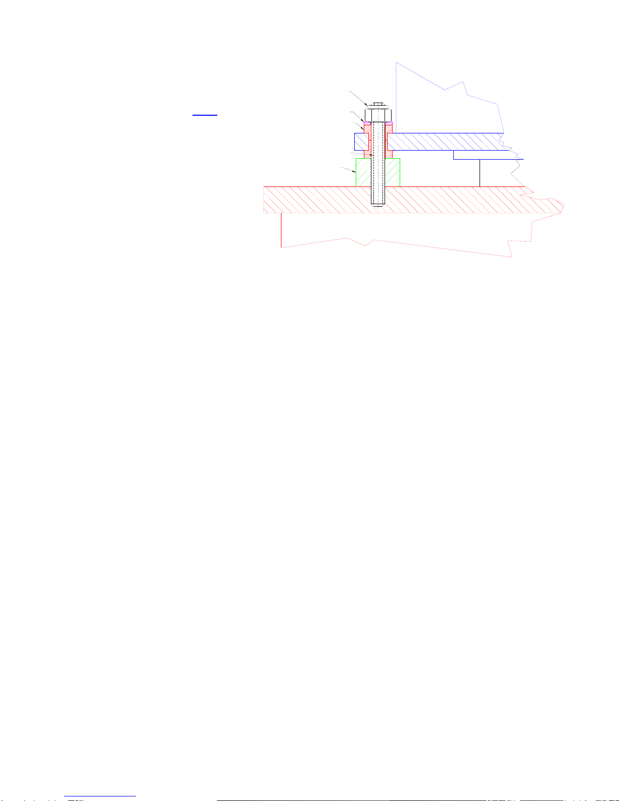
Mounting instructions for bevel box mounting:
Washer Ø8,5 x Ø16
Rubber damper transmission drive unit
bevel gearbox
Stud M8x60
M8 Nyloc nut
autopilot flange
M8 Nyloc nut
•Screw the 4 M8x60 studs into the
autopilot flange.
•Mount the 4 off M8 nyloc nuts.
Tighten well with 20Nm torque.
•Mount the drive unit.
•Mount the 4 off washers.
•Mount the 4 off nyloc nuts. Don’t
tighten too hard to prevent damage
of the rubber damper (3 Nm).
Transmission drive type TS250 installation guide version 1.4 page 2 of 4
Mounting instructions for reduction gearbox mounting:
Transmission drive type TS250 installation guide version 1.4 page 3 of 4
•Screw the 4 M8x60 studs into
the autopilot flange. Tighten
well and use loctite to lock
the thread.
of the rubber
damper (3 Nm).
est the system:
tted limiting the rudder travel to an equal travel of 36 degrees from
ghtened and will not
lete system from port to starboard making sure the rosejoints don’t hit the output lever
t lever to go “over dead centre” so it can’t return to the initial position any more, blocking the
system.
. Failing to install this fuse could mechanically overload the drive
ausing severe damage inside the drive unit.
potential damage to the structure. If motion is detected, one can rule out the drive causing the
alfunction.
aintenance:
the draglink. These balls are easy exchangeable and available for
round 10 € each from any Jefa distributor.
•Mount the 4 off delrin
Washer Ø8,5 x Ø16
Rubber damper transmission drive unit
reduction gearbox
4pcs black POM spacer
Ø25mm, hight=16mm
Stud M8x60
M8 Nyloc nut
spacers.
•Mount the drive unit.
•Mount the 4 off washers.
•Mount the 4 off nyloc nuts.
Don’t tighten too hard to
prevent damage
T
Before you can test the system, make sure following things are correct:
•Solid rudder stops should be fi
midships to port and starboard.
•Make sure all bolted parts (tiller pins, rosejoints, draglinks, tillerarm,etc) are firmly ti
come loose even when exposed to heavy vibrations. Use locktite when necessary.
•Move the comp
and tiller lever.
•Make sure the drive output lever rotates equally around 65 degrees to both sides and there is no risk for
the outpu
Connect the electronics. Make absolutely sure the autopilot is set to “reversible drive” or equivalent. Don’t use
settings like “solenoid” or “hydraulic drive” as these settings will disable the speed control of the autopilot leaving
the drive running at 100% speed or 0%, but nothing in between. Make sure the clutch voltage is set to the
correct voltage. Some brands have a default clutch voltage that has to be changed. B&G uses 9 volts as
standard, Raymarine uses 12 volts, both even on 24 volts input. This should be adjusted to the correct voltage
to guarantee a proper working of the clutch. The B&G and Raymarine course computer has to be opened for dip
switches to be changed. The Simrad pilot can be adjusted via software in the setup menu on the screen. Always
fit the delivered fuse into the power feed line
c
When the drive doesn’t react to the electronics, test the drive by bypassing it: Connect a plus and minus wire to
the battery or fuse box and first connect the clutch, one should here a click when connecting and disconnecting.
With the clutch under power, connect power for a short time to the motor cables. The system should get in
motion now. Don’t connect the cables too long as the drive will try to continue, even when the rudder stops are
reached, with
m
M
The direct drive is “greased for life”, so should no be opened. No maintenance is required except for periodic
checks of all bolted connections. As the rudder system, the steering system and the autopilot drive is exposed
to heavy vibrations (mainly by cruising on motor), all bolted connections should be yearly checked. The only
parts that could wear in time are the balls of
a

Declaration of conformity:
requirements of
e Electro Magnetic Compatibility Directive Standard contained within Standard No. 60945/A1.
…………………………. Date: 06-10-2003
Stig Jensen
For more information please visit our website www.jefa.com
I, Stig Jensen of Jefa Marine Steering ApS, Nimbusvej 2, 2670 Greve, Denmark, confirm that the Jefa 250Nm
transmission drive, when fitted in accordance with these installation instructions, will meet the
th
Signed:…………………………………
04.09.2009
Jef S
E-mail: [email protected]
a Steering Ap
Agenavej 43
26Denmark
70 GREVE
Tel: +45-46155210
Fax: +45-43695211
Transmission drive type TS250 installation guide version 1.4 page 4 of 4
This manual suits for next models
2
Table of contents


