Jefferson Electric Buck-Boost Series Instructions for use

Jefferson Electric Inc. 1-800-892-3755 www.jeffersonelectric.com
Buck-Boost Application manual 02-12 Page 1 of 21
JEFFERSON ELECTRIC, INC.
Buck-Boost Transformer Application Manual
Revised on February 15, 2012
Table of Contents
I. Introduction............................................................................................................. 2
II. Choosing the Proper Transformer........................................................................... 2
III. Rapid Selector Charts ............................................................................................. 4
Single Phase Chart.................................................................................................. 4
Open Delta Chart .................................................................................................... 6
Wye Chart............................................................................................................... 7
IV. Connection Instructions and Diagrams................................................................... 9
Single Phase............................................................................................................ 9
3 Phase Wye.......................................................................................................... 11
3 Phase Open Delta............................................................................................... 15
V. Typical Questions ................................................................................................. 20
VI. Misapplications..................................................................................................... 21

Jefferson Electric Inc. 1-800-892-3755 www.jeffersonelectric.com
Buck-Boost Application manual 02-12 Page 2 of 21
I. Introduction
Jefferson Electric Buck-Boost transformers are low voltage isolation transformers that
can be connected in an auto-transformer arrangement to provide a convenient and
economical way to raise or lower single and three-phase voltages from 5-20%. The auto-
transformer arrangement allows smaller and less expensive Buck-Boost transformers to
supply large power loads.
This application manual provides the information to properly select and install a Buck-
Boost transformer. Sections of this manual include the answers to typical questions,
common misapplications and the wiring diagrams for most applications.
Important notes regarding Buck-Boost Transformers;
•Buck-Boost transformers do not compensate for fluctuating voltages, they
will always increase or decrease the voltage by a constant percentage of
the source voltage.
•Buck-Boost transformers do not provide electrical isolation from the
source voltage. If electrical isolation is required a separate isolation
transformer must be used.
•When using transformers connected per these wiring diagrams, check
local electrical code requirements regarding the use of auto-transformers
to ensure compliance.
II. Choosing the Proper Transformer
You will need the following information to select the appropriate transformer for your
application;
♦Phase requirement, single phase or three phase
♦Three phase Load wiring, 3-wire or 4-wire
♦Source voltage
♦Load voltage
♦Load KVA or Amperage
Step 1: What is the load: Single-Phase or Three-Phase?
♦If single-phase: Go to Single-Phase Chart.
♦If three-phase: Is the load 3-wire or 4-wire?
oThree wire: You can use the Open Delta Chart or the Wye Chart.
oFour wire: You must make sure you have a wye source, if not see
misapplication M3, otherwise go to the Wye Chart.

Jefferson Electric Inc. 1-800-892-3755 www.jeffersonelectric.com
Buck-Boost Application manual 02-12 Page 3 of 21
Step 2: What is the source and load voltage?
♦-Are you stepping up or stepping down the voltage?
oStepping up: Go to the LV column in the charts and find your source
voltage.
oStepping down: Go to the HV column in the charts and find your source
voltage.
♦After locating the source voltage in the charts, find your load voltage.
oStepping up: Go to the HV column in the charts and find your load
voltage.
oStepping down: Go to the LV column in the charts and find your load
voltage.
♦Please note that you might not find the exact voltage because of the fixed change
of the buck-boost transformer. So locate the closest voltage to your load voltage
and determine if this is acceptable for your application. Note the Catalog number
shown, (e.g. 416-12xx)
Step 3: What is the amperage required by the load or the KVA of the load?
From the voltages that you have chosen, go across the chart until you find a
maximum current greater than your required current or a maximum KVA greater
than your maximum load KVA.
Step 4: From this current or KVA you will complete the catalog number for the buck-
boost transformer required.
Go up the chart to the top of the column and you will find two numbers (e.g. 11,
21, 31, etc). Place these two numbers at the end of the catalog number chosen
above in place of the xx, (e.g. 416-1231). The catalog number is completed by
adding a –000 to the end. (e.g. 416-1231-000).
Step 5: Order the number of units that are required, located in the title of the charts (1
for single-phase, 2 for open delta and 3 for wye configurations).
Step 6: Note the diagram number at the end of the row of the selected voltages. Connect
the transformers per the diagram listed for the transformers you have chosen. See
Section IV for wiring diagrams.

Jefferson Electric Inc. 1-800-892-3755 www.jeffersonelectric.com
Buck-Boost Application manual 02-12 Page 4 of 21
III. Rapid Selector Charts
Single Phase Chart (requires 1 transformer)
Low
Voltage
(LV)
High
Voltage
(HV)
Catalog
Number Load
Required 01 11 21 31 41 51 61 71 81 91 New
Diagram
#
Old
Diagram
#
95 120 416-12xx
KVA
Amperes 0.37
3.95 0.56
5.93 0.94
9.89 1.8
19.7 2.8
29.6 3.7
39.5 5.6
59.3 7.5
79.1 11.2
118 18.8
197 2 56-B
100 120 416-11xx
KVA
Amperes 0.50
5.0 0.75
7.5 1.25
12.5 2.5
25.0 3.7
37.0 5.0
50.0 7.5
75.0 10.0
100 15.0
150 25.0
250 2 56-B
106 120 416-12xx
KVA
Amperes 0.75
7.07 1.12
10.5 1.87
17.6 3.7
34.9 5.6
52.8 7.5
70.7 11.2
105 15.0
141 22.5
212 37.0
349 1 56-A
109 120 416-11xx
KVA
Amperes 1.0
9.17 1.5
13.7 2.5
22.9 5.0
45.8 7.5
68.8 10.0
91.7 15.0
137 20.0
183 30.0
275 50.0
458 1 56-A
120 132 416-11xx
KVA
Amperes 1.10
9.17 1.65
13.7 2.75
22.9 5.5
45.8 8.2
68.8 11.0
91.7 16.5
137 22.0
183 33.0
275 55.0
458 1 56-A
120 136 416-12xx
KVA
Amperes 0.85
7.08 1.27
10.5 2.12
17.6 4.2
35.0 6.3
52.5 8.5
70.8 12.7
105 17.0
141 25.5
212 42.0
350 1 56-A
120 144 416-11xx
KVA
Amperes 0.60
5.0 0.90
7.5 1.50
12.5 3.0
25.0 4.5
37.5 6.0
50.0 9.0
75.0 12.0
100 18.0
150 30.0
250 2 56-B
120 152 416-12xx
KVA
Amperes 0.47
3.91 0.71
5.91 1.18
9.83 2.3
19.1 3.5
29.1 4.7
39.1 7.1
59.1 9.5
79.1 14.2
118 23.0
191 2 56-B
200 240 416-14xx
KVA
Amperes 0.50
2.50 0.75
3.75 1.25
6.25 2.5
12.5 3.7
18.7 5.0
25.0 7.5
37.5 10.0
50.0 15.0
75.0 25.0
125 2 56-B
208 236 416-12xx
KVA
Amperes 0.73
3.53 1.1
5.28 1.84
8.82 3.6
17.4 5.5
26.4 7.3
35.3 11.0
52.8 14.7
70.7 22.1
106 36.8
174 4 56-D
212 240 416-12xx
KVA
Amperes 0.75
3.53 1.12
5.28 1.87
8.82 3.7
17.4 5.6
26.4 7.5
35.3 11.2
52.8 15.0
70.7 22.5
106 37.0
174 4 56-D

Jefferson Electric Inc. 1-800-892-3755 www.jeffersonelectric.com
Buck-Boost Application manual 02-12 Page 5 of 21
Low
Voltage
(LV)
High
Voltage
(HV)
Catalog
Number Load
Required 01 11 21 31 41 51 61 71 81 91 New
Diagram
#
Old
Diagram
#
208 230 416-11xx
KVA
Amperes 0.95
4.58 1.4
6.88 2.3
11.4 4.7
22.9 7.1
34.4 9.5
45.8 14.3
68.8 19.0
91.7 28.6
137 47.6
229 4 56-D
218 240 416-11xx
KVA
Amperes 1.0
4.58 1.5
6.88 2.5
11.4 5.0
22.9 7.5
34.4 10.0
45.8 15.0
68.8 20.0
91.7 30.0
137 50.0
229 4 56-D
225 240 416-12xx
KVA
Amperes 1.5
6.66 2.25
10.0 3.75
16.6 7.5
33.3 11.2
49.7 15.0
66.6 22.5
100 30.0
133 45.0
200 75.0
333 3 56-C
230 276 416-14xx
KVA
Amperes 0.57
2.5 0.86
3.75 1.43
6.25 2.8
12.5 4.3
18.7 5.7
25.0 8.6
37.5 11.5
45.0 17.2
75.0 28.7
124 2 56-B
240 252 416-11xx
KVA
Amperes 2.1
8.75 3.15
13.1 5.25
21.8 10.5
43.7 15.7
65.4 21.0
87.5 31.5
131 42.0
175 63.0
262 105
437 3 56-C
240 264 416-11xx
KVA
Amperes 1.1
4.58 1.65
6.87 2.75
11.4 5.5
22.9 8.2
34.1 11.0
45.8 16.5
68.7 22.0
91.6 33.0
137 55.0
229 4 56-D
240 272 416-12xx
KVA
Amperes 0.85
3.54 1.27
5.29 2.12
8.83 4.2
17.5 6.3
26.2 8.5
35.4 12.7
52.9 17.0
70.8 25.5
106 42.0
175 4 56-D
240 288 416-14xx
KVA
Amperes 0.60
2.5 0.90
3.75 1.5
6.25 3.0
12.5 4.5
18.7 6.0
25.0 9.0
37.5 12.0
50.0 18.0
75.0 30.0
125 2 56-B
437 480 416-14xx
KVA
Amperes 1.0
2.28 1.5
3.43 2.5
5.72 5.0
11.4 7.5
17.1 10.0
22.8 15.0
34.3 20.0
45.7 30.0
68.6 50.0
114 4 56-D
457 480 416-14xx
KVA
Amperes 2.0
4.37 3.0
6.56 5.0
10.9 10.0
21.8 15.0
32.8 20.0
43.7 30.0
65.6 40.0
87.5 60.0
131 100
218 3 56-C
480 504 416-14xx
KVA
Amperes 2.1
4.37 3.15
6.56 5.25
10.9 10.5
21.8 15.7
32.8 21.0
43.7 31.5
65.6 42.0
87.5 63.0
131 105
218 3 56-C
480 528 416-14xx
KVA
Amperes 1.1
2.29 1.65
3.43 2.75
5.72 5.5
11.4 8.2
17.0 11.0
22.9 16.5
34.3 22.0
45.8 33.0
68.7 55.0
114 4 56-D

Jefferson Electric Inc. 1-800-892-3755 www.jeffersonelectric.com
Buck-Boost Application manual 02-12 Page 6 of 21
Open Delta Chart (requires 2 transformers)
Low
Voltage
(LV)
High
Voltage
(HV)
Catalog
Number Load
Required 01 11 21 31 41 51 61 71 81 91 New
Diagram # Old
Diagram #
416- KVA 0.86 1.29 2.1 4.3 6.4 8.6 12.9 17.2 25.0 43.0
200 240 14xx Amperes 2.1 3.1 5.1 10.3 15.4 20.7 31.0 41.4 60.1 103 10 57-B
416- KVA 1.27 1.91 3.1 6.3 9.5 12.7 19.1 25.5 38.2 63.7
208 236 12xx Amperes 3.1 4.7 7.6 15.4 23.2 31.1 46.7 62.4 93.4 156 12 57-D
416- KVA 1.29 1.94 3.2 6.4 9.7 12.9 19.4 25.8 38.0 64.0
212 240 12xx Amperes 3.1 4.7 7.7 15.4 23.3 31.0 46.7 62.1 91.4 154 12 57-D
416- KVA 1.65 2.47 4.1 8.2 12.3 16.5 24.7 33.0 49.5 82.5
208 230 11xx Amperes 4.1 6.2 10.3 20.6 30.9 41.4 62.0 82.8 124 207 12 57-D
416- KVA 1.73 2.59 4.3 8.6 12.9 17.3 25.9 34.6 51.0 86.0
218 240 11xx Amperes 4.2 6.2 10.3 20.7 31.0 41.6 62.3 83.2 123 207 12 57-D
416- KVA 2.59 3.89 6.4 12.9 19.4 25.9 38.9 51.9 77.0 129
225 240 12xx Amperes 6.2 9.4 15.4 31.0 46.7 62.3 93.6 124.8 185 310 11 57-C
416- KVA 3.46 5.18 8.6 17.3 25.9 34.6 51.8 69.2 103 173
229 240 11xx Amperes 8.3 12.5 20.7 41.6 62.3 83.2 124.6 166.5 248 416 11 57-C
416- KVA 1.81 2.72 4.5 9.0 13.6 18.1 27.2 36.3 54.0 90.0
230 253 14xx Amperes 4.1 6.2 10.3 20.5 31.0 41.3 62.1 82.8 123 205 9 57-A
416- KVA 0.99 1.49 2.4 4.9 7.4 9.9 14.9 19.9 29.0 49.0
230 276 14xx Amperes 2.1 3.1 5.0 10.2 15.5 20.7 31.2 41.6 60.7 103 10 57-B
416- KVA 3.64 5.47 9.1 18.2 27.2 36.4 54.7 72.8 109 182
240 252 11xx Amperes 8.3 12.5 20.8 41.7 62.3 83.4 125.3 166.8 250 417 11 57-C
416- KVA 1.9 2.86 4.7 9.5 14.2 19.0 28.6 38.1 57.0 95.0
240 264 11xx Amperes 4.2 6.3 10.3 20.8 31.1 41.6 62.5 83.3 125 208 12 57-D
416- KVA 1.47 2.2 3.6 7.3 11.0 14.7 22.0 29.4 44.1 73.6
240 272 12xx Amperes 3.1 4.7 7.6 15.5 23.3 31.2 46.7 62.4 93.6 156 12 57-D
416- KVA 1.03 1.55 2.5 5.1 7.7 10.3 15.5 20.7 31.0 51.0
240 288 14xx Amperes 2.1 3.1 5.0 10.2 15.4 20.6 31.1 41.5 62.1 102 10 57-B
416- KVA 1.73 2.59 4.3 8.6 12.9 17.3 25.9 34.6 51.0 86.0
437 480 14xx Amperes 2.1 3.1 5.2 10.3 15.5 20.8 31.2 41.6 61.3 103 12 57-D
416- KVA 3.46 5.18 8.6 17.3 25.9 34.6 51.8 69.2 103 173
457 480 14xx Amperes 4.2 6.2 10.3 20.8 31.2 41.6 62.3 83.2 124 208 11 57-C

Jefferson Electric Inc. 1-800-892-3755 www.jeffersonelectric.com
Buck-Boost Application manual 02-12 Page 7 of 21
Low
Voltage
(LV)
High
Voltage
(HV)
Catalog
Number Load
Required 01 11 21 31 41 51 61 71 81 91 New
Diagram # Old
Diagram #
416- KVA 3.64 5.47 9.1 18.2 27.2 36.4 54.7 72.8 109 183
480 504 14xx Amperes 4.2 6.3 10.4 20.8 31.2 41.7 62.7 83.4 125 210 11 57-C
416- KVA 1.9 2.86 4.7 9.5 14.2 19.0 28.6 38.1 57.0 95.0
480 528 14xx Amperes 2.1 3.1 5.1 10.4 15.5 20.8 31.3 41.7 62.3 104 12 57-D
Wye Chart (requires 3 transformers)
Low
Voltage
(LV)
High
Voltage
(HV)
Catalog
Number Load
Required 01 11 21 31 41 51 61 71 81 91 New
Diagram
#
Old
Diagram
#
164 208 416-12xx
KVA
Amperes 1.1
3.89 1.7
5.89 2.8
9.79 5.6
18.9 8.4
29.4 11.2
38.9 16.8
58.9 22.0
78.9 34.0
117 56.0
197 6 58-B
173 208 416-11xx
KVA
Amperes 1.50
5.0 2.20
7.5 3.7
12.5 7.5
25.0 11.2
37.0 15.0
50.0 22.5
75.0 30.0
100 45.0
150 75.0
250 6 58-B
183 208 416-12xx
KVA
Amperes 2.2
7.07 3.3
10.5 5.6
17.6 11.2
34.9 16.8
52.8 22.5
70.7 33.7
105 45.0
141 67.0
212 112
354 5 58-A
189 208 416-11xx
KVA
Amperes 3.0
9.17 4.5
13.7 7.5
22.9 15.0
45.8 22.5
68.8 30.0
91.7 45.0
137 60.0
183 90.0
275 150
458 5 58-A
208 229 416-11xx
KVA
Amperes 3.3
9.17 4.9
13.7 8.2
22.9 16.5
45.8 24.7
68.8 33.0
91.7 49.5
137 66.0
183 99.0
275 165
458 5 58-A
208 235 416-12xx
KVA
Amperes 2.5
7.08 3.8
10.5 6.3
17.6 12.7
35.0 19.1
52.5 25.5
70.8 38.2
105 51.0
141 76.5
212 127
350 5 58-A
208 249 416-11xx
KVA
Amperes 1.80
5.0 2.70
7.5 4.5
12.5 9.0
25.0 13.5
37.5 18.0
50.0 27.0
75.0 36.0
100 54.0
150 90.0
250 6 58-B
208 263 416-12xx
KVA
Amperes 1.4
3.91 2.1
5.91 3.5
9.83 7.1
19.1 10.6
29.1 14.2
39.1 21.4
59.1 28.0
79.1 42.0
118 71.0
191 6 58-B
346 416 416-14xx
KVA
Amperes 1.50
2.5 2.2
3.75 3.7
6.25 7.5
12.5 11.2
18.5 15.0
25.0 22.5
37.5 30.0
50.0 45.0
75.0 75.0
125 6 58-B
367 416 416-12xx
KVA
Amperes 2.2
3.53 3.3
5.28 5.6
8.82 11.2
17.4 16.8
26.4 22.5
35.3 33.7
52.8 45.0
70.7 67.0
106 112
174 8 58-D

Jefferson Electric Inc. 1-800-892-3755 www.jeffersonelectric.com
Buck-Boost Application manual 02-12 Page 8 of 21
Low
Voltage
(LV)
High
Voltage
(HV)
Catalog
Number Load
Required 01 11 21 31 41 51 61 71 81 91 New
Diagram
#
Old
Diagram
#
378 416 416-11xx
KVA
Amperes 3.0
4.58 4.5
6.88 7.5
11.4 15.0
22.9 22.5
34.4 30.0
45.8 45.0
68.8 60.0
91.7 90.0
137 150
229 8 58-D
390 416 416-12xx
KVA
Amperes 4.5
6.66 6.7
10.0 11.2
16.6 22.5
33.3 33.7
49.7 45.0
66.6 67.5
100 90.0
133 135
200 225
333 7 58-C
397 416 416-11xx
KVA
Amperes 6.0
8.73 9.0
13.1 15.0
21.8 30.0
43.6 45.0
65.5 60.0
87.3 90.0
131 120
174 180
262 300
436 7 58-C
398 438 416-14xx
KVA
Amperes 3.1
4.56 4.7
6.82 7.8
11.3 15.7
22.6 23. 6
33.9 31.5
45.6 47.2
68.2 63.0
91.3 94.0
136 157
229 5 58-A
398 478 416-14xx
KVA
Amperes 1.7
2.50 2.5
3.75 4.3
6.25 8.6
12.5 12.9
18.7 17.2
25.0 25.9
37.5 34.0
50.0 51.0
75.0 86.0
125 6 58-B
416 437 416-11xx
KVA
Amperes 6.3
8.75 9.4
13.1 15.7
21.8 31.5
43.7 47.2
65.4 63.0
87.5 94.5
131 126
175 189
262 315
437 7 58-C
416 443 416-12xx
KVA
Amperes 4.8
6.66 7.2
10.0 12.0
16.6 24.0
33.3 36.0
50.0 48.0
66.6 72.0
100 96.0
133 144
200 240
333 7 58-C
416 457 416-11xx
KVA
Amperes 3.3
4.58 4.9
6.87 8.2
11.4 16.5
22.9 24.7
34.1 33.0
45.8 49.5
68.7 66.0
91.6 99.0
137 165
229 8 58-D
416 471 416-12xx
KVA
Amperes 2.5
3.54 3.8
5.29 6.3
8.83 12.7
17.5 19.1
26.2 25.5
35.4 38.2
52.9 51.0
70.8 76.5
106 127
175 8 58-D
416 498 416-14xx
KVA
Amperes 1.80
2.5 2.7
3.75 4.5
6.25 9.0
12.5 13.5
18.7 18.0
25.0 27.0
37.5 36.0
50.0 54.0
75.0 90.0
125 6 58-B

Jefferson Electric Inc. 1-800-892-3755 www.jeffersonelectric.com
Buck-Boost Application manual 02-12 Page 9 of 21
IV. Connection Instructions and Diagrams
Single Phase
WIRING DIAGRAM #1 (56-A)
Step 1: Connect LV1, H1, H3 & HV1 together.
Step 2: Connect H2, H4, LV2, X1 & X3 together.
Step 3: Connect X2, X4 & HV2 together.
WIRING DIAGRAM #2 (56-B)
Step 1: Connect LV1, H1, H3 & HV1 together.
Step 2: Connect H2, H4, LV2 & X1 together.
Step 3: Connect X2 & X3 together.
Step 4: Connect X4 & HV2 together.
Jefferson Electric Inc. 1-800-892-3755 www.jeffersonelectric.com
Buck-Boost Application manual 02-12 Page 10 of 21
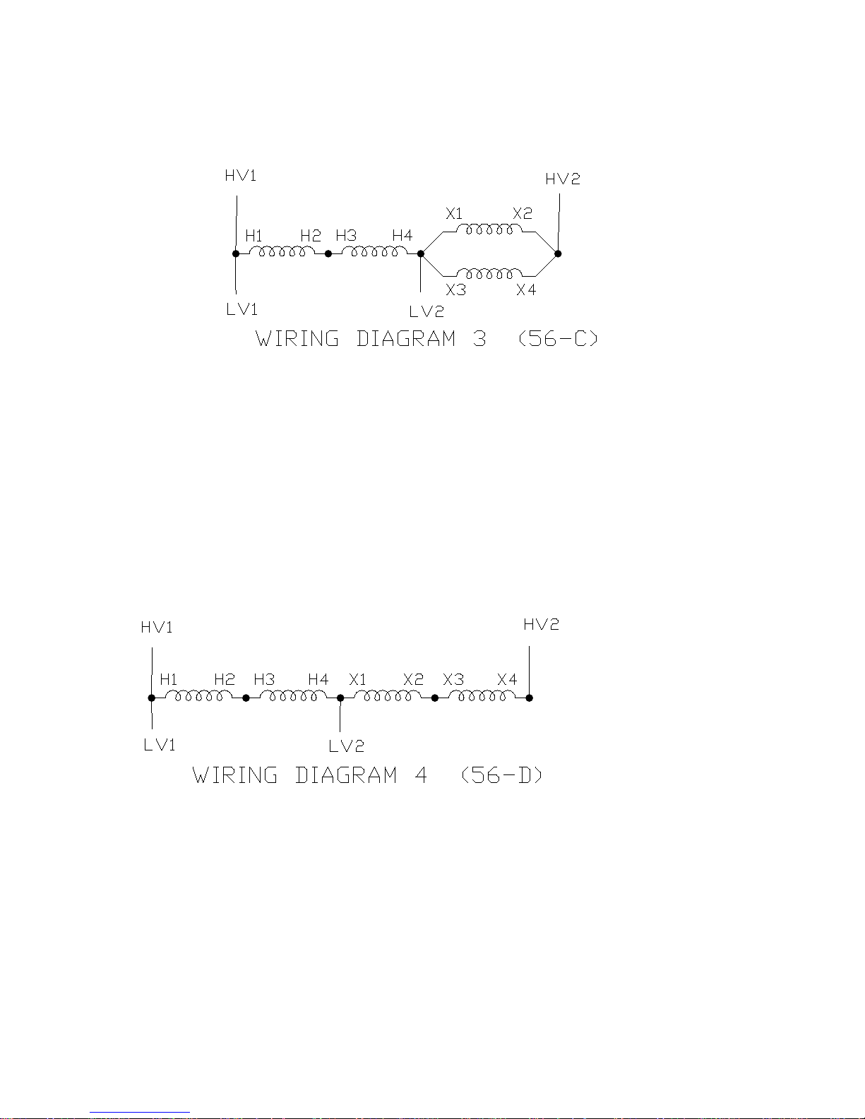
WIRING DIAGRAM #3 (56-C)
Step 1: Connect LV1, H1 & HV1 together.
Step 2: Connect H2 & H3 together.
Step 3: Connect H4, LV2, X1 & X3 together.
Step 4: Connect X2, X4 & HV2 together.
WIRING DIAGRAM #4 (56-D)
Step 1: Connect LV1, H1 & HV1 together.
Step 2: Connect H2 & H3 together.
Step 3: Connect H4, LV2 & X1 together.
Step 4: Connect X2 & X3 together.
Step 5: Connect X4 & HV2 together
Jefferson Electric Inc. 1-800-892-3755 www.jeffersonelectric.com
Buck-Boost Application manual 02-12 Page 11 of 21
3 Phase Wye
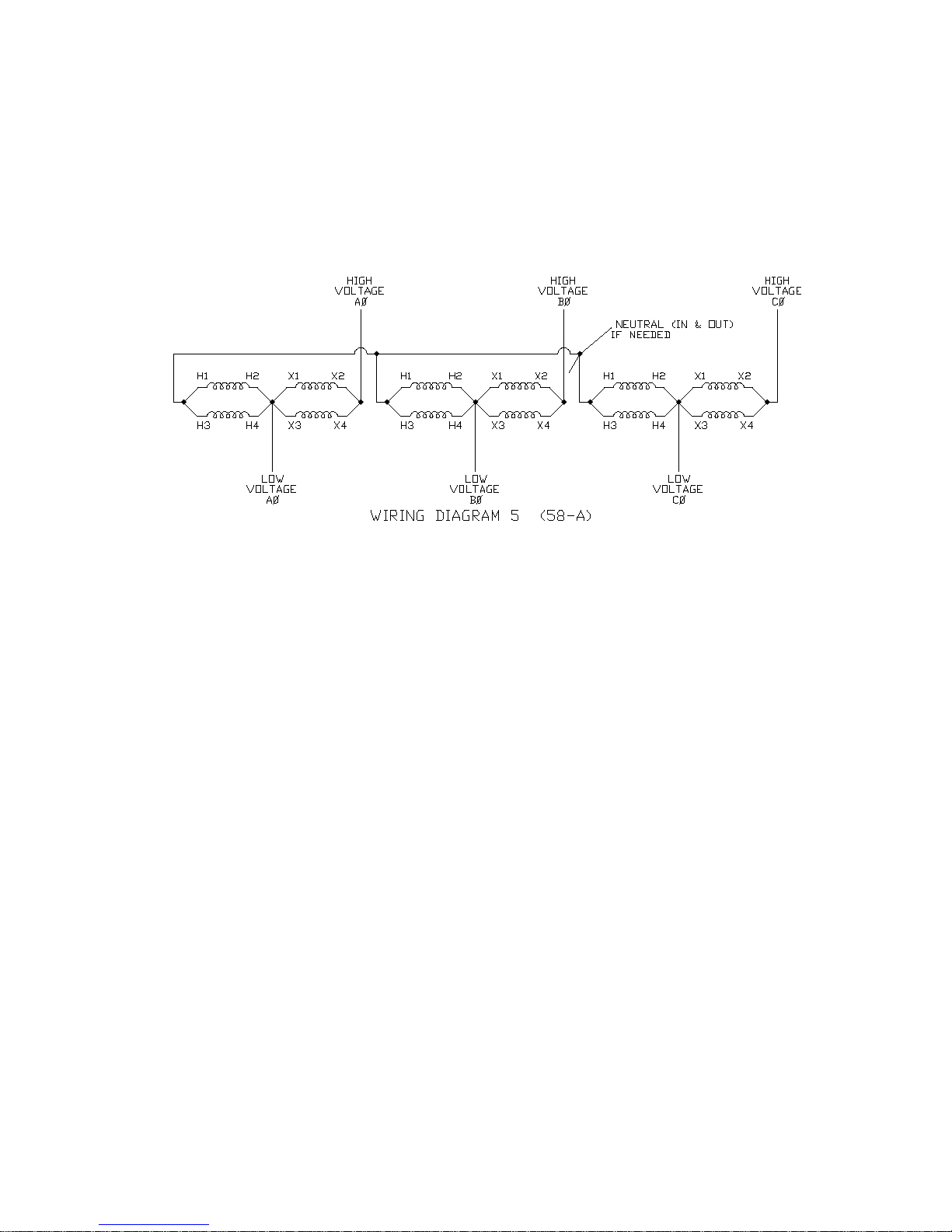
WIRING DIAGRAM #5 (58-A)
Part A (Transformer #1):
Step 1: Connect H1 & H3 together.
Step 2: Connect H2, H4, X1, X3 & LOW VOLTAGE AØ-Phase together.
Step 3: Connect X2, X4 & HIGH VOLTAGE AØ-Phase together.
Part B (Transformer #2):
Step 1: Connect H1 & H3 together.
Step 2: Connect H2, H4, X1, X3 & LOW VOLTAGE BØ-Phase together.
Step 3: Connect X2, X4 & HIGH VOLTAGE BØ-Phase together.
Part C (Transformer #3):
Step 1: Connect H1 & H3 together.
Step 2: Connect H2, H4, X1, X3 & LOW VOLTAGE CØ-Phase together.
Step 3: Connect X2, X4 & HIGH VOLTAGE CØ-Phase together.
Part D:
Connect H1 from Transformer #1, H1 from Transformer #2, H1 from
Transformer #3, the LV neutral & the HV neutral together.
Transformer #1 Transformer #2 Transformer #3
Jefferson Electric Inc. 1-800-892-3755 www.jeffersonelectric.com
Buck-Boost Application manual 02-12 Page 12 of 21
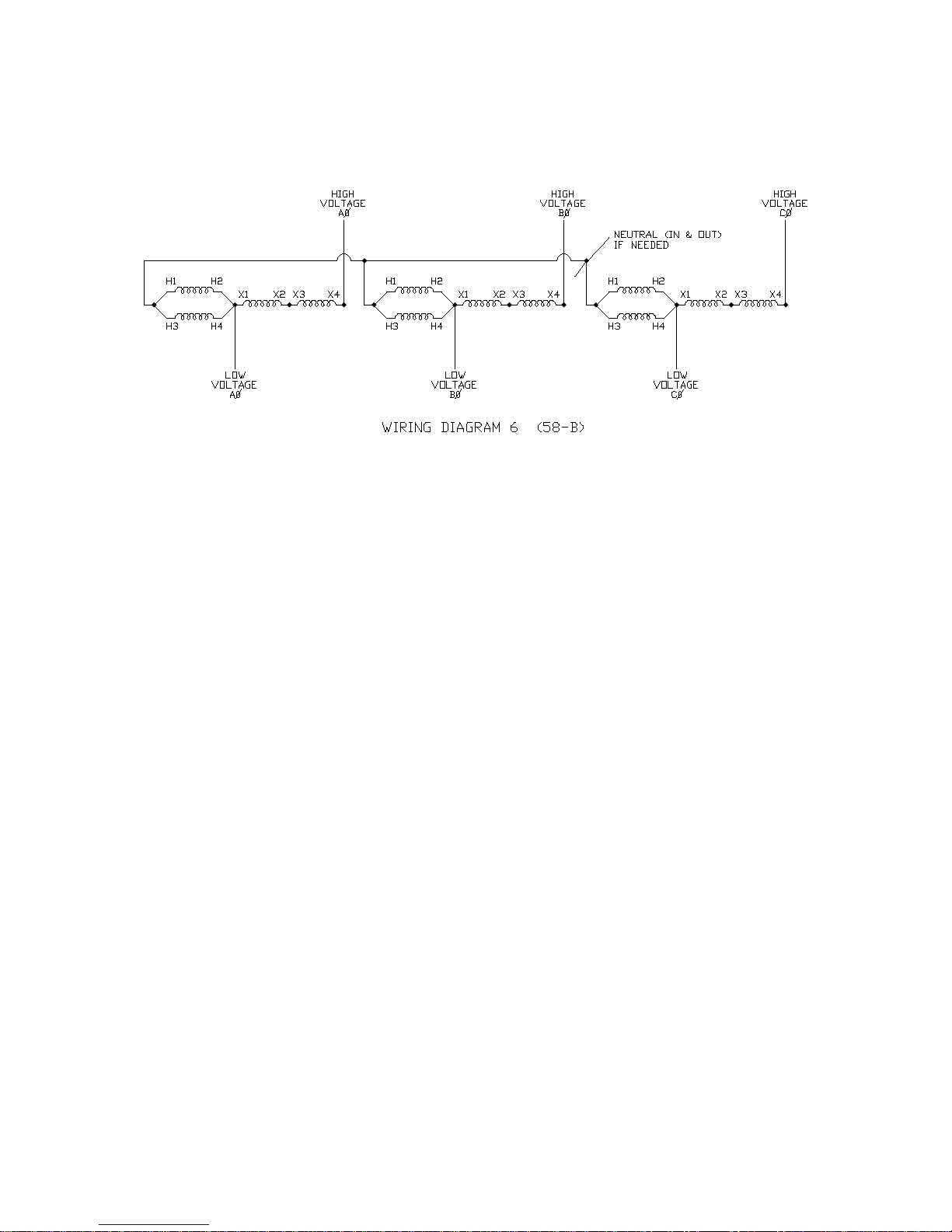
WIRING DIAGRAM #6 (58-B)
Part A (Transformer #1):
Step 1: Connect H1 & H3 together.
Step 2: Connect H2, H4, X1 & LOW VOLTAGE AØ-Phase together.
Step 3: Connect X2 & X3 together.
Step 4: Connect X4 & HIGH VOLTAGE AØ-Phase together.
Part B (Transformer #2):
Step 1: Connect H1 & H3 together.
Step 2: Connect H2, H4, X1 & LOW VOLTAGE BØ-Phase together.
Step 3: Connect X2 & X3 together.
Step 4: Connect X4 & HIGH VOLTAGE BØ-Phase together.
Part C (Transformer #3):
Step 1: Connect H1 & H3 together.
Step 2: Connect H2, H4, X1 & LOW VOLTAGE CØ-Phase together.
Step 3: Connect X2 & X3 together.
Step 4: Connect X4 & HIGH VOLTAGE CØ-Phase together.
Part D:
Connect H1 from Transformer #1, H1 from Transformer #2, H1 from
Transformer #3, the LV neutral & the HV neutral together.
Transformer #1 Transformer #2 Transformer #3
Jefferson Electric Inc. 1-800-892-3755 www.jeffersonelectric.com
Buck-Boost Application manual 02-12 Page 13 of 21
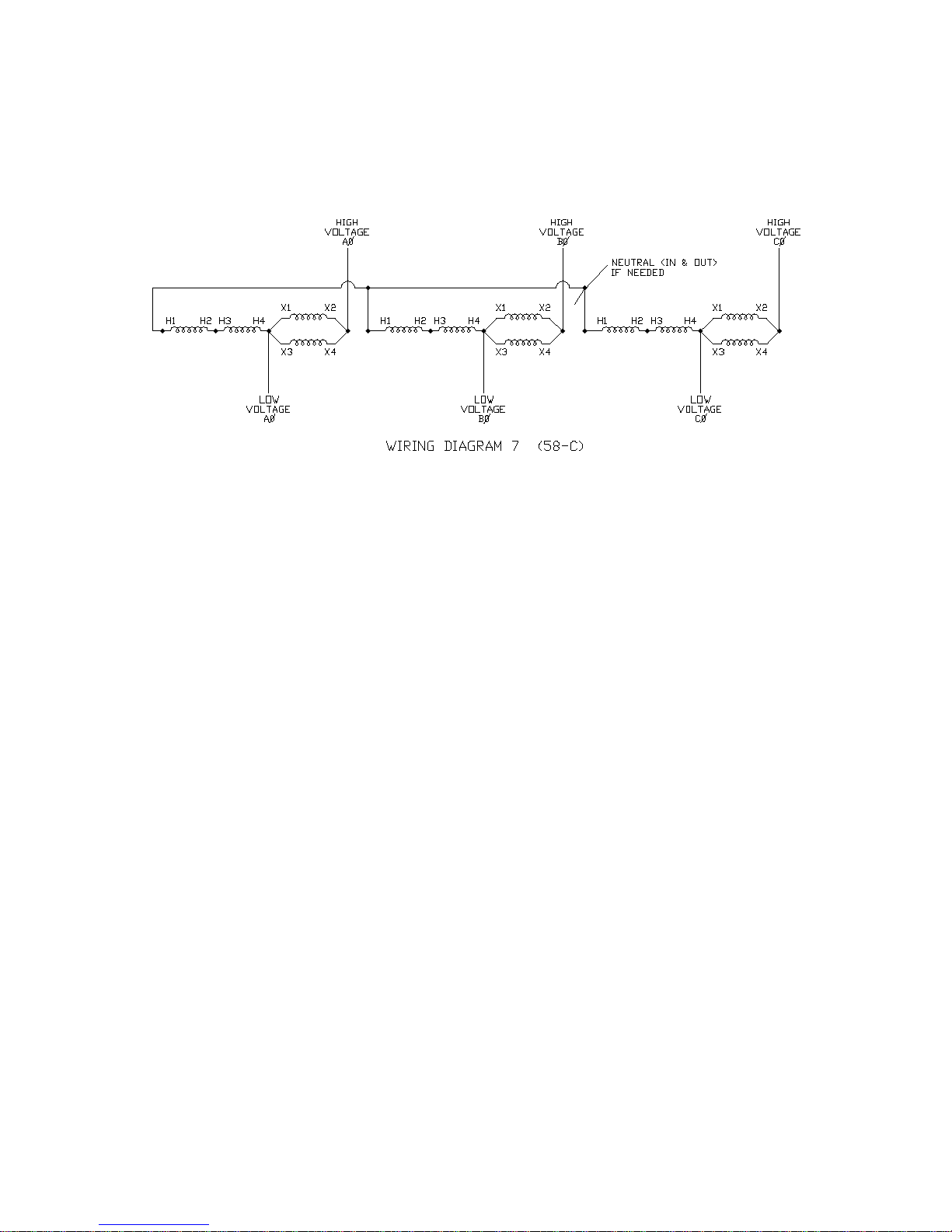
WIRING DIAGRAM #7 (58-C)
Part A (Transformer #1):
Step 1: Connect H2 & H3 together.
Step 2: Connect H4, X1, X3 & LOW VOLTAGE AØ-Phase together.
Step 3: Connect X2, X4 & HIGH VOLTAGE AØ-Phase together.
Part B (Transformer #2):
Step 1: Connect H2 & H3 together.
Step 2: Connect H4, X1, X3 & LOW VOLTAGE BØ-Phase together.
Step 3: Connect X2, X4 & HIGH VOLTAGE BØ-Phase together.
Part C (Transformer #3):
Step 1: Connect H2 & H3 together.
Step 2: Connect H4, X1, X3 & LOW VOLTAGE CØ-Phase together.
Step 3: Connect X2, X4 & HIGH VOLTAGE CØ-Phase together.
Part D:
Connect H1 from Transformer #1, H1 from Transformer #2, H1 from
Transformer #3, the LV neutral & the HV neutral together.
Transformer #1 Transformer #2 Transformer #3

Jefferson Electric Inc. 1-800-892-3755 www.jeffersonelectric.com
Buck-Boost Application manual 02-12 Page 14 of 21
WIRING DIAGRAM #8 (58-D)
Part A (Transformer #1):
Step 1: Connect H2 & H3 together.
Step 2: Connect H4, X1 & LOW VOLTAGE AØ-Phase together.
Step 3: Connect X2 & X3 together.
Step 4: Connect X4 & HIGH VOLTAGE AØ-Phase together.
Part B (Transformer #2):
Step 1: Connect H2 & H3 together.
Step 2: Connect H4, X1 & LOW VOLTAGE BØ-Phase together.
Step 3: Connect X2 & X3 together.
Step 4: Connect X4 & HIGH VOLTAGE BØ-Phase together.
Part C (Transformer #3):
Step 1: Connect H2 & H3 together.
Step 2: Connect H4, X1 & LOW VOLTAGE CØ-Phase together.
Step 3: Connect X2 & X3 together.
Step 4: Connect X4 & HIGH VOLTAGE CØ-Phase together.
Part D:
Connect H1 from Transformer #1, H1 from Transformer #2, H1 from
Transformer #3, the LV neutral & the HV neutral together.
Transformer #1 Transformer #2 Transformer #3

Jefferson Electric Inc. 1-800-892-3755 www.jeffersonelectric.com
Buck-Boost Application manual 02-12 Page 15 of 21
3 Phase Open Delta
WIRING DIAGRAM #9 (57-A)
Part A (Transformer #1):
Step 1: Connect X2, X4 & HIGH VOLTAGE AØ-Phase together.
Step 2: Connect X1, X3, H2, H4 & LOW VOLTAGE AØ-Phase together.
Step 3: Connect H1 & H3 together.
Part B (Transformer #2):
Step 1: Connect X2, X4 & HIGH VOLTAGE CØ-Phase together.
Step 2: Connect X1, X3, H2, H4 & LOW VOLTAGE CØ-Phase together.
Step 3: Connect H1 & H3 together.
Part C:
Connect H1 from Transformer #1, H1 from Transformer #2, HIGH VOLTAGE
BØ-Phase & LV B-Phase together.
Transformer #1 Transformer #2
Jefferson Electric Inc. 1-800-892-3755 www.jeffersonelectric.com
Buck-Boost Application manual 02-12 Page 16 of 21
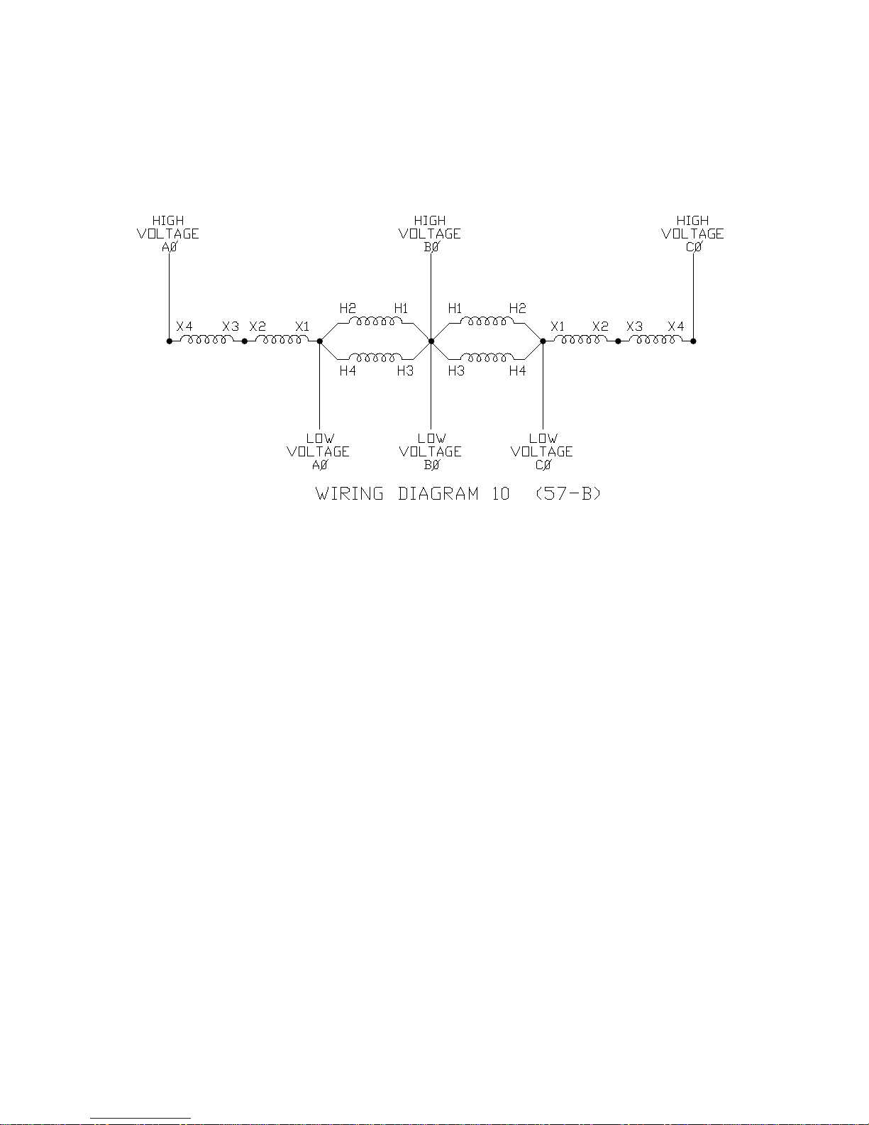
WIRING DIAGRAM #10 (57-B)
Part A (Transformer #1):
Step 1: Connect X4 & HIGH VOLTAGE AØ-Phase together.
Step 2: Connect X2 & X3 together.
Step 3: Connect X1, H2, H4 & LOW VOLTAGE AØ-Phase together.
Step 4: Connect H1 & H3 together.
Part B (Transformer #2):
Step 1: Connect X4 & HIGH VOLTAGE CØ-Phase together.
Step 2: Connect X2 & X3 together.
Step 3: Connect X1, H2, H4 & LOW VOLTAGE CØ-Phase together.
Step 4: Connect H1 & H3 together.
Part C:
Connect H1 from Transformer #1, H1 from Transformer #2, HIGH VOLTAGE
BØ-Phase & LV B-Phase together
Transformer #1 Transformer #2
Jefferson Electric Inc. 1-800-892-3755 www.jeffersonelectric.com
Buck-Boost Application manual 02-12 Page 17 of 21
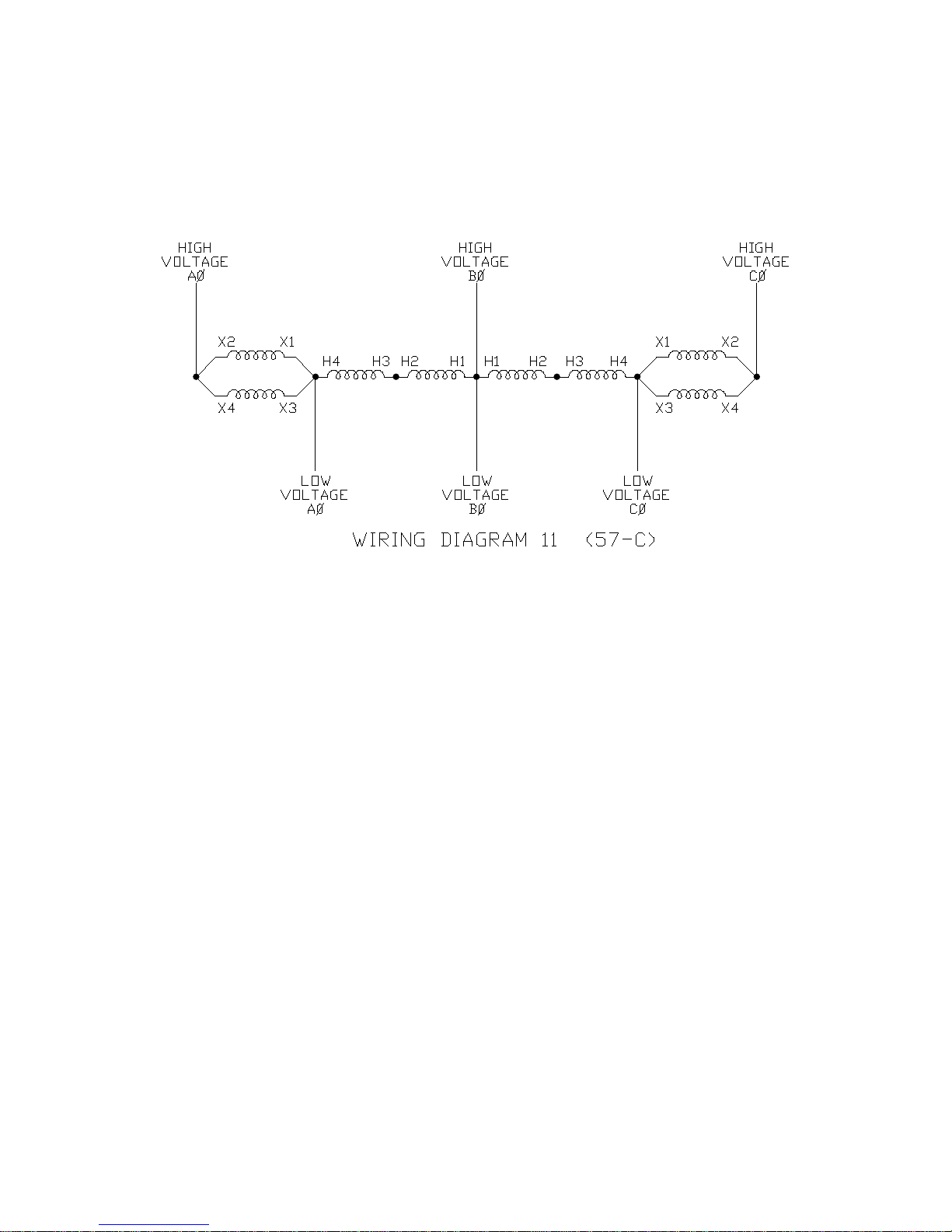
WIRING DIAGRAM #11 (57-C)
Part A (Transformer #1):
Step 1: Connect X2, X4 & HIGH VOLTAGE AØ-Phase together.
Step 2: Connect X1, X3, H4 & LOW VOLTAGE AØ-Phase together.
Step 3: Connect H2 & H3 together.
Part B (Transformer #2):
Step 1: Connect X2, X4 & HIGH VOLTAGE CØ-Phase together.
Step 2: Connect X1, X3, H4 & LOW VOLTAGE CØ-Phase together.
Step 3: Connect H2 & H3 together.
Part C:
Connect H1 from Transformer #1, H1 from Transformer #2, HIGH VOLTAGE
BØ-Phase & LV B-Phase together.
Transformer #1 Transformer #2

Jefferson Electric Inc. 1-800-892-3755 www.jeffersonelectric.com
Buck-Boost Application manual 02-12 Page 18 of 21
WIRING DIAGRAM #12 (57-D)
Part A (Transformer #1):
Step 1: Connect X4 & HIGH VOLTAGE AØ-Phase together.
Step 2: Connect X2 & X3 together.
Step 3: Connect X1, H4 & LOW VOLTAGE AØ-Phase together.
Step 4: Connect H2 & H3 together.
Part B (Transformer #2):
Step 1: Connect X4 & HIGH VOLTAGE CØ-Phase together.
Step 2: Connect X2 & X3 together.
Step 3: Connect X1, H4 & LOW VOLTAGE CØ-Phase together.
Step 4: Connect H2 & H3 together.
Part C:
Connect H1 from Transformer #1, H1 from Transformer #2, and HIGH
VOLTAGE BØ-Phase & LV B-Phase together.
Transformer #1 Transformer #2

Jefferson Electric Inc. 1-800-892-3755 www.jeffersonelectric.com
Buck-Boost Application manual 02-12 Page 19 of 21
V. Typical Questions
Q1. What is the difference between an autotransformer and an isolation transformer?
A1. In an isolation transformer the input and output are completely separated and all
the energy is transformed. In an autotransformer the input and output are
electrically connected. Only a portion of the electrical energy is changed in an
autotransformer, the remainder flowing directly between the primary and the
secondary. An autotransformer is typically smaller, lighter and less costly than a
comparable isolation transformer.
Q2. When using the transformer as a step-up (boost) does the lower voltage get
connected to the LV or HV terminals?
A2. When connecting the Buck-Boost transformer per our wiring diagrams, the
diagrams are not set up as step-up or step-down, they can be used in either
application. The LV side is always the lower of the two voltages and the HV side
is always the higher of the two voltages.
Q3. Why do I measure different voltages between the lines and neutral? I purchased
your unit and need to go from 208 volts to 240 volts, when I take my
measurements from neutral to my lines I get 120 volts from one line to neutral
and 130 to 140 volts from the other line to neutral.
A3. The measurements are correct, but this configuration is not recommended. The
unequal voltages are due to the fact that one line is being boosted by 13.3%. See
better solutions offered in the description of misapplication M1.
Q4. Can I use a Buck-Boost Transformer to provide an output of 208Y/120 (or any
other wye combination)?
A4. This all depends on your source. If you have a wye source, you can feed the wye
through the autotransformer. If you have a High-Leg Delta or a 3-wire source,
you can not create the wye for your application and must purchase an Isolation
style transformer.
Q5. When do I use an Open Delta configuration and when do I use a Wye
configuration?
A5. This all depends on your load requirements. If your load requires a wye and you
meet the criteria from question #4, then you need a wye configuration. If you
have a 3-wire load it is your choice on the Open Delta or Wye configuration.
Please note that you may want to take availability and cost of the transformers
into consideration when you make your decision. An Open Delta requires 2
transformers compare to using 3 slightly smaller transformers for the wye
configuration.

Jefferson Electric Inc. 1-800-892-3755 www.jeffersonelectric.com
Buck-Boost Application manual 02-12 Page 20 of 21
Q6. Why does the nameplate read High Volts =120 x 240 and Low Volts = 12/24,
when the chart shows that I can connect 208 volts in and 229 volts out ?
A6. The nameplate shows the rating for when the unit is used as an isolation
transformer. When the transformers are used as auto-transformers they are only
“transforming” a portion of the total voltage.
Q7. Why do I have larger capacity wire then what is in the transformer?
A7. You have a larger capacity wire because you have sized yours for the current that
is required for your load and source. Our wires are smaller in capacity because of
the features of an autotransformer that subtracts the current in the common coil.
Since the current that will flow through our wires is less, the capacity of the wire
can be smaller.
VI. Misapplications
M1. Pulling the neutral around the transformer on a single-phase application. This
usually occurs when the source voltage is 208Y/120 and you need to feed a
single-phase panel with 120/240.
What occurs is that you size the buck-boost unit to go from 208 volts up to 240
(236) volts, obtain the units and boost the voltage between your lines from 208
volts to 236 volts. You pull this new voltage to the panel and since the panel
requires a neutral, you take the neutral from your 208Y/120 source and pull it to
the panel.
When taking voltage measurements you realize that from one line to neutral is
120 volts, but from the other line to neutral you have a higher voltage than 120,
somewhere between 130 and 145 volts. This occurs because on the
autotransformer connection line one is a common line between the input and the
output. Since it is directly connected to the input, the voltage between line and
neutral stays at 120 volts. The other line has been boosted 13.3%, so the voltage
to neutral has also been boosted. That is why the voltage is higher than 120 volts.
Two Solutions:
1. The correct transformer is an isolation transformer rated 208 volts to 120/240
volts.
2. A second choice is to use the buck-boost transformer for the 240 volt loads only,
the 120 volt loads can be fed by using the source 208Y/120 volts.
M2. Using a buck-boost transformer to correct voltage drop. This application is load
dependent, voltage drop occurs because of I2x R losses. (These losses are also
Table of contents


