ATS-US usage methods
10.
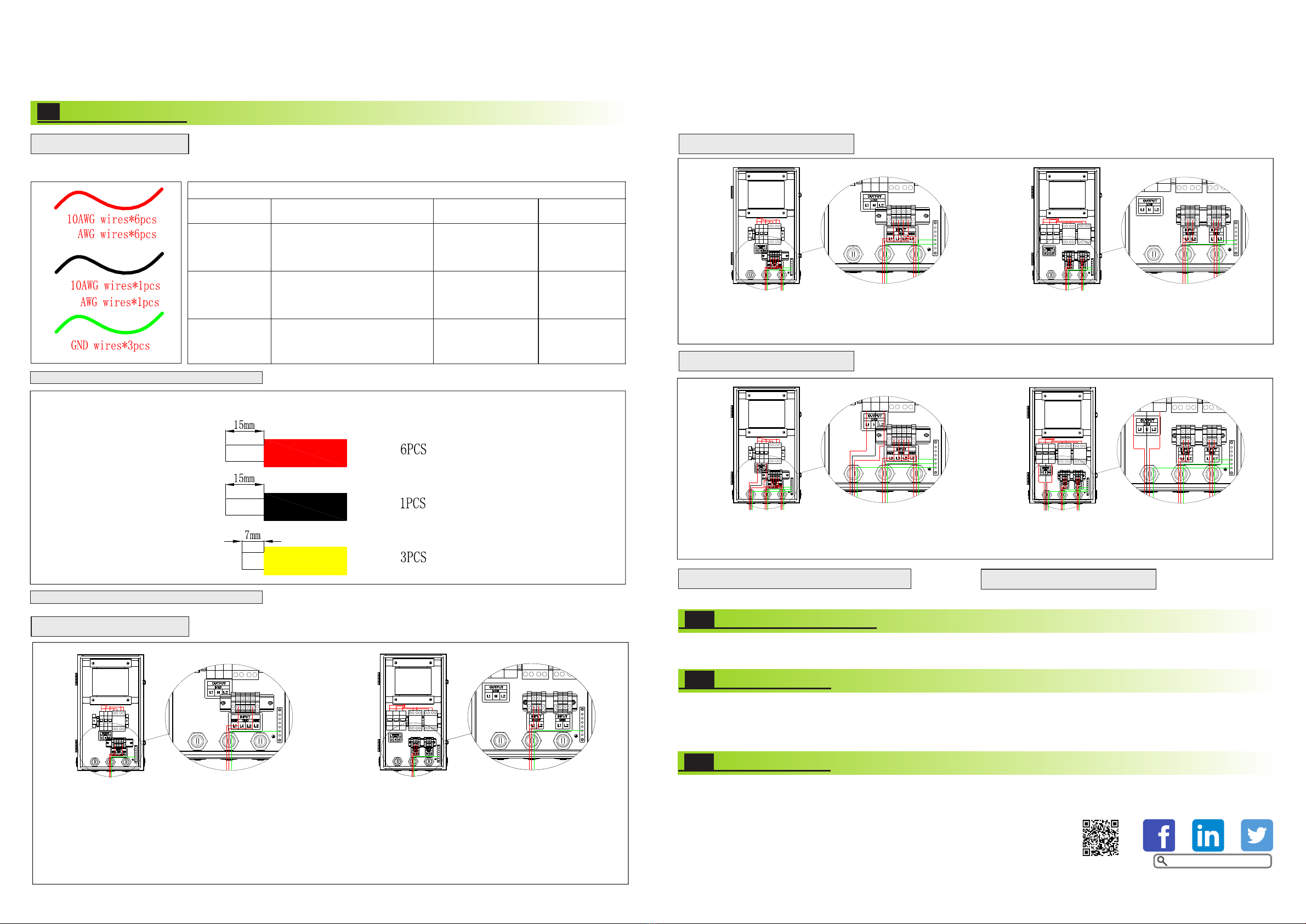
Wiring Connection
9.
9.1 Wires Making
1. Wires below are needed before installation.
Conductor Cross-
sectional Area Range
1.Use cables that can withstand
90°C (194°F) or 105°C (221°F).
2.use four single-core outdoor
copper cables (L1, N, L2, PE).
L1, N, L2:10–6 AWG
PE: 6 AWG
1.Use cables that can withstand
90°C (194°F) or 105°C (221°F).
2.Two single-core outdoor copper
cables (L1 and L2)
1.Use cables that can withstand
90°C (194°F) or 105°C (221°F).
2.use four single-core outdoor
copper cables (L1, N, L2, PE).
L1, N, L2:10–6 AWG
PE: 6 AWG
2. Use the diagonal plier to trip 15mm of insulation from one side of the 10AWG wires (7pcs).
Use the diagonal plier to trip one side of GND wire about 7mm (3pcs).
9.2 BACKUP Connection
1.Use the screwdriver to loosen screws in positions L1 and L2 at the contactor’s BACKUP inputs.
2.Insert L1 and L2 of the backup conductors into the BACKUP input terminals of L1 and L2.
3.Tighten to 2.5Nm.
4.Use the screwdriver to secure the backup EGC to the grounding bus bar.
9.4 LOAD Connecrion
After connecting the ATS-US internal wire, close the cover and the GRID and EPS end of the ATS-US are respectively connected with the AC
GRID and EPS output of inverter, EPS load end access load. Run the system, loaded into normal operation.
Trouble shooting
11.
1. In the process of use, if EPS load does not work in on-grid condition, please turn off the inverter and turn off the switch of grid input. Then
open the ATS-US cover, check the GRID and EPS LOAD line is connected properly.
2. If there is no power in load in off-grid condition, please turn off the inverter and open the ATS-US cover, check the control line, the EPS
wiring and the EPS LOAD wiring is properly.
1. Please use the equipment within the scope of specification. Excessive current or voltage may cause device damage.
2. To avoid personal injury due to energy hazard, remove wristwatches and jewelry when repairing. Use tools with insulated handles.
3.The rated power of secondary side L1-N and L2-N could up to 5KVA respectively,and power difference between the tow split phases can not
exceed 3KW.
4.Don't connect N of ATS together with N of grid.
5.Don't connect N of ATS to PE of ATS or PE of grid.
6. Repair is to be performed only by qualified technical personal authorized by manufacturer.
The rated balanced power(L-N)means the Load of L1-N and L2-N is equal.
The rated unbalanced power(L-N)means the load of L1-N and L2-N is different.
Caution
12.
GR-UM-198-A-06
a
8b
8
a
b
9.3 GRID Connection
b
ab
b
a
9.5 Checking
Please make sure that all wiring in the ATS-US is tightened.
Picture above a:ATS 5000T-US,b:ATS 11400T-US
10AWGab
8AWG
10AWGab
8AWG
10AWGab
8AWG
10AWGab
8AWG
10AWGab
8AWG
Picture above a:ATS 5000T-US,b:ATS 11400T-US
以上图形a代表ATS 5000T-US,b代表ATS 11400T-US Picture above a:ATS 5000T-US,b:ATS 11400T-US
a
Growatt New Energy
Download
Manual
1. Use the screwdriver to loosen screws in positions L1 and L2 at the contactor's GRID inputs.
2. Insert L1 and L2 of the GRID conductors in to the GRID input terminals of L1 and L2.
3. Tighten to 2.5Nm.
4. Use screwdriver to secure the GRID EGC to the grounding bus bar.
1. Use the screwdriver to loosen the three screws on the LOAD terminals.
2. Insert L1, L2, and N of the LOAD conductors in to the L1 ,L2, and LOAD terminals.
3. Tighten to 3.5Nm.
4. Use screwdriver to secure the LOAD EGC to the grounding bus bar.


