Jefferson Professional Tools & Equipment JEFC200L10B-230 User manual

User Manual
v.2.3
JEFC200L10B-230
AIR COMPRESSOR
200L
230V ~ 50Hz • 10Bar • 3HP • BELT DRIVE
All manuals and user guides at all-guides.com

USER MANUAL
JEFC200L10B-230
200L AIR COMPRESSOR •230V~50Hz •3HP • 10Bar • BELT DRIVE
www.jeffersontools.com
2
All manuals and user guides at all-guides.com

USER MANUAL
JEFC200L10B-230
200L AIR COMPRESSOR •230V~50Hz •3HP • 10Bar • BELT DRIVE
www.jeffersontools.com
3
Introduction 4
Specications 4
Unpacking & Assembly 5
Equipment Identication 6
Before First Use 7
Safety Guidelines 8
Warning Labels 10
Safety Valve 11
Operation Guide 11
Maintenance 13
Troubleshooting 14
Environmental Protection 15
WEEE Waste Electrical and Electronic Equipment Statement 15
Parts Diagram - Main Assembly 16
Parts List - Main Assembly 17
Parts Diagram - Pump 18
Parts List - Pump 19
EC Declaration of Conformity 20
Limited Warranty Statement 21
CONTENTS
All manuals and user guides at all-guides.com

USER MANUAL
JEFC200L10B-230
200L AIR COMPRESSOR •230V~50Hz •3HP • 10Bar • BELT DRIVE
www.jeffersontools.com
4
ABOUT THIS DOCUMENT
This manual has been compiled by Jefferson Tools and is an integrated part of the product with which it's enclosed and should be kept with it for
future reference. Please read all of the information supplied in this User Manual before operating this product.
This manual describes the purpose for which the product has been designed and contains all the necessary information to ensure its correct and
safe use. We recommend that you read the information supplied before carrying out any maintenance or repair. By following all the general safety
instructions contained in this manual you will help to ensure operator safety and extend the potential life span of the equipment.
All photographs and drawings in this manual are supplied by Jefferson Tools to help illustrate the operation of the product. Whilst every effort
has been made to ensure accuracy of information contained in this manual our policy of continuous improvement determines the right to make
modifications without prior warning.
The information contained in this Instruction Manual is designed to assist you in the safe operation and maintenance of the compressor. Some
illustrations in this Instruction Manual may show details or attachments that differ from those on your own compressor. Contact your nearest
Jefferson Dealer if you are unsure about any information included in this manual or require any additional information about the safe use, operation
maintenance, or repair of this equipment.
INTRODUCTION
• 200L Belt-driven compressor suitable for professional workshops
• Fitted with a heavy duty single-phase 3HP motor
• Heavy-duty cylinders with alloy heads for improved heat dissipation
• Comes complete with pressure regulator with moisture trap
• Large and solid wheels for ease of mobility
• Twin front castor wheel for improved stability and manoeuvrability
• Drive guards offer protection to the y-wheel and belt assembly
• Powder-coated tank
• Twin pressure gauges showing tank and working pressure
SPECIFICATIONS
Model Number: JEFC200L10B-230
Tank Capacity: 200L
Motor: 3HP (2.2kW)
Maximum Pressure: 10bar (145psi)
Plug Type / Rated Supply: UK 3-Pin / 13A
Cylinders: 2
Pump Speed: 1060rpm
Air Displacement: 14.4cfm (408 L/min)
Free Air Delivery: (F.A.D) 9.8cfm (277 L/min)
Input Voltage ~ Frequency: 230V ~ 50Hz
Guaranteed Sound Power Level: 96 dB(A)
Lubrication Oil / Capacity: Jefferson HT68 Compressor Oil
Weight: NW: 104kg / GW: 122kg
Dimensions: 1410 x 510 x 970mm
All manuals and user guides at all-guides.com

USER MANUAL
JEFC200L10B-230
200L AIR COMPRESSOR •230V~50Hz •3HP • 10Bar • BELT DRIVE
www.jeffersontools.com
5
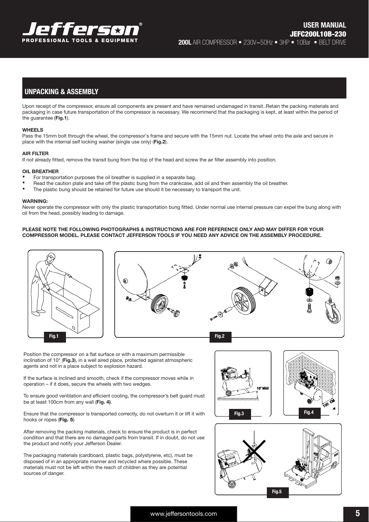
Upon receipt of the compressor, ensure all components are present and have remained undamaged in transit..Retain the packing materials and
packaging in case future transportation of the compressor is necessary. We recommend that the packaging is kept, at least within the period of
the guarantee (Fig.1).
WHEELS
Pass the 15mm bolt through the wheel, the compressor's frame and secure with the 15mm nut. Locate the wheel onto the axle and secure in
place with the internal self locking washer (single use only) (Fig.2).
AIR FILTER
If not already tted, remove the transit bung from the top of the head and screw the air lter assembly into position.
OIL BREATHER
• For transportation purposes the oil breather is supplied in a separate bag.
• Read the caution plate and take off the plastic bung from the crankcase, add oil and then assembly the oil breather.
• The plastic bung should be retained for future use should it be necessary to transport the unit.
WARNING:
Never operate the compressor with only the plastic transportation bung tted. Under normal use internal pressure can expel the bung along with
oil from the head, possibly leading to damage.
PLEASE NOTE THE FOLLOWING PHOTOGRAPHS & INSTRUCTIONS ARE FOR REFERENCE ONLY AND MAY DIFFER FOR YOUR
COMPRESSOR MODEL. PLEASE CONTACT JEFFERSON TOOLS IF YOU NEED ANY ADVICE ON THE ASSEMBLY PROCEDURE.
Position the compressor on a at surface or with a maximum permissible
inclination of 10° (Fig.3), in a well aired place, protected against atmospheric
agents and not in a place subject to explosion hazard.
If the surface is inclined and smooth, check if the compressor moves while in
operation – if it does, secure the wheels with two wedges.
To ensure good ventilation and efcient cooling, the compressor’s belt guard must
be at least 100cm from any wall (Fig. 4).
Ensure that the compressor is transported correctly, do not overturn it or lift it with
hooks or ropes (Fig. 5)
After removing the packing materials, check to ensure the product is in perfect
condition and that there are no damaged parts from transit. If in doubt, do not use
the product and notify your Jefferson Dealer.
The packaging materials (cardboard, plastic bags, polystyrene, etc), must be
disposed of in an appropriate manner and recycled where possible. These
materials must not be left within the reach of children as they are potential
sources of danger.
UNPACKING & ASSEMBLY
Fig.3 Fig.4
Fig.2Fig.1
Fig.5
All manuals and user guides at all-guides.com

USER MANUAL
JEFC200L10B-230
200L AIR COMPRESSOR •230V~50Hz •3HP • 10Bar • BELT DRIVE
www.jeffersontools.com
6
1. Air Tank 10. Oil Sight Glass
2. Pressure Gauge 11. Pressure Regulator
3. Air Outlet (Quick Release) 12. Pressure Gauge
4. Pressure Switch 13. Check Valve
5. Transportation Handle 14. Tank Rating Plate
6. Belt Guard 15. Ball Valve
7. Motor Assembly 16. Back Wheels
8. Air Filter 17. Tank Drain Valve
9. Pump Assembly 18. Front Castors
1
EQUIPMENT IDENTIFICATION
2
3
4
5
6
7
9
10
8
11
12
13
15
14
16
17
18
All manuals and user guides at all-guides.com

USER MANUAL
JEFC200L10B-230
200L AIR COMPRESSOR •230V~50Hz •3HP • 10Bar • BELT DRIVE
www.jeffersontools.com
7
Check the oil Level:
Before using the compressor check the oil level
using the dipstick. If the oil is not up to the mark it
should be topped up with Jefferson HT68
Compressor Oil (see Fig.6).
Sight glass / Oil Level:
The compressor oil level can be viewed through the
sight glass; the compressor must be on a level
surface to measure the oil level through the sight
glass accurately (see Fig.7):
• The top of the red dot indicates the full mark
• The bottom of the red dot indicates the low mark
Important: Always ensure that the oil level is correct before operating the compressor.
Ensure that the working environment is suitable for use:
This compressor must be used on a at, level surface The maximum safe operating angle
in any direction is 15° degrees (see Fig.8).
• Do not operate the compressor on inclines in excess of 10° degrees.
• Serious damage to pump components may result from insufcient lubrication.
• Never use the air compressor on a rooftop or elevated position that could allow the
unit to fall or be tipped over.
• Use additional air hose for elevated jobs.
Check that the power supply is correct for this compressor:
It is essential that the air compressor has an adequate power supply.
Always utilize more air hose before choosing to use an extension lead, as low voltage could cause
damage to the motor. (Low voltage damage is not covered under warranty)
Read and understand all the electrical safety guidelines laid out in this manual, follow all applicable local authority safety guidelines.
BEFORE FIRST USE
Fig.6 Fig.7
Fig.8Fig.8
10°
All manuals and user guides at all-guides.com

USER MANUAL
JEFC200L10B-230
200L AIR COMPRESSOR •230V~50Hz •3HP • 10Bar • BELT DRIVE
www.jeffersontools.com
8
Read and ensure that you understand all of the operating instructions, safety precautions and warnings in this Instruction
Manual before operating or maintaining this compressor. Most accidents that result from compressor operation and
maintenance are caused by the failure to observe basic safety rules or precautions. An accident can often be avoided by
recognizing a potentially hazardous situation before it occurs, and by observing appropriate safety procedures. Hazards
that must be avoided to prevent bodily injury or machine damage are identied by warnings on the compressor and in this
Instruction Manual. Never use this compressor or modify it in any way that has not been specically recommended by the
manufacturer. Contact a qualied electrician for advice on any issues relating to electrical safety in your working environment.
ELECTRICAL SAFETY
Ensure that you check the equipment thoroughly to ensure it is safe and t for purpose before each use. It is important that
you inspect all plugs, sockets, power cables and electrical ttings for wear and damage and repair or replace any defective
components. The risk of electric shock can be minimised by the correct use of the appropriate electrical safety devices.
• We recommend that you t a Residual Current Circuit Breaker (RCCB) in the main distribution
board and that a Residual Current Device (RCD) is used when operating this equipment.
• The Electricity at Work Act 1989 includes legislation that places legal implications on employers
to ensure the safety of electrical devices in the workplace. The regulations dictate that all portable
equipment must be inspected regularly and tested to ensure that it is safe for use. 'Portable
equipment' means any electrical item that can be moved and this is often referred to as Portable
Appliance Testing (PAT). PAT testing should be carried out regularly on this equipment by trained,
authorised personnel, as required by the legislation.
• The Health and Safety at Work Act 1974 states that it is the responsibility of the owner of electrical
appliances to ensure that both the equipment and working environments are maintained to ensure
safe operation at all times.
• Check that all equipment cables are secure, correctly insulated, free from damage, and protected against short circuit and overload before
connecting to the power supply. Do not use worn or damaged cables, plugs, sockets or other ttings.
• Ensure that the power supply matches voltage requirements specied on the equipment and that the plug is wired correctly and tted with
the correct fuse (See Fig.9).
• If the electrical fuse blows, ensure it is replaced by an identical type of fuse with the same rating.
• Never pull or manoeuvre this equipment into position using the power cable (move using the handle).
• Ensure the power cable is kept away from heat, oil and sharp edges.
• We recommend that the equipment is connected directly to the power supply without the use of extension leads as the resulting voltage drop
can reduce motor and pump performance.
• Always disconnect the compressor from the power source and remove the compressed air from the air tank before servicing, inspecting,
maintaining, cleaning, replacing or checking any parts.
• Do not carry the compressor while it is connected to its power source or when the air tank is lled with compressed air. Be sure the pressure
switch is in the “Off” position before connecting the compressor to its power source.
• Do not use the compressor in damp / wet conditions.
SAFETY GUIDELINES
Fig.9
Cable Grip
Neutral
Wire
(Blue)
Earth
Wire
(Brown)
Earth Wire
(Yellow
& Green) 13 Amp
Fuse
All manuals and user guides at all-guides.com

USER MANUAL
JEFC200L10B-230
200L AIR COMPRESSOR •230V~50Hz •3HP • 10Bar • BELT DRIVE
www.jeffersontools.com
9
EQUIPMENT SAFETY
• Never place your hands, ngers or other body parts near the compressor’s moving parts during operation. Ensure that the equipment is
isolated from the power supply and all switches in the OFF position before carrying out maintenance, repairs or adjustments.
• Never operate this compressor without all guards or safety features in place and in proper working order. If maintenance or servicing requires
the removal of a guard or safety features, be sure to replace the guards or safety features before resuming operation of the compressor.
• Always wear safety goggles or equivalent eye protection. Compressed air must never be aimed at anyone or any part of the body.
• When not in use, the compressor should be stored in dry place. Keep out of reach of children. Keep children and animals away from the work
area.
• Clear all work areas of unnecessary tools, debris, furniture etc. prior to use. Cluttered work areas can lead to injuries.
• Do not wear loose clothing or jewellery when operating this equipment. They can be caught in moving parts. Wear protective hair covering to
contain long hair.
• Follow instructions for lubricating this equipment as required.
• Watch what you are doing and remove any potential distractions before use. Use common sense at all times.
• Do not operate this equipment when you are tired or if you are under the inuence of alcohol, drugs or medication that makes you drowsy.
• Check for the correct alignment of moving parts, binding of moving parts, condition of parts, mounting, and air leaks, and any other issues
that might affect the safe operation of this equipment. A guard or other part that is damaged should be properly repaired or replaced by
an authorized Jefferson service centre unless otherwise indicated elsewhere in this instruction manual. Have defective pressure switches
replaced by an authorized service centre. Do not use compressor if the switch does not turn it on and off.
• Operate the compressor according to the instructions provided in this manual. Never allow the compressor to be operated by children,
individuals unfamiliar with its operation or unauthorized personnel.
• Keep all screws, bolts, and plates tightly mounted. Check regularly.
• The motor air vent must be kept clean so that air can freely ow at all times. Check for dust build-up frequently and clean as required.
• If the equipment appears to be operating unusually, making strange noises, or otherwise appears defective, stop using it immediately and
arrange for repairs by a authorized service centre.
• Solvents such as petrol, thinner, benzine, carbon tetrachloride, and alcohol may damage and crack plastic parts. Do not wipe them with such
solvents. Wipe plastic parts with a soft cloth lightly dampened with soapy water and dry thoroughly.
• Only use Jefferson approved replacement parts. Non-approved parts will void your warranty and can lead to malfunction and resulting
injuries. Genuine parts are available from Jefferson your dealer.
• Do not modify the compressor for any use other than which it was designed for by the manufacturer. Do not tamper with or attempt to adjust
the tank, pressure switch or safety valve. Never strap anything to the tank. Do not subject the tank to impact, vibration, heat, abrasion or
corrosive materials.
• Always contact an authorized service centre for advice on any repairs. Unauthorized modication may not only impair the compressor
performance but may also result in accident or injury to repair personnel who do not have the required knowledge and technical expertise to
perform the repair operations correctly.
• When the compressor is not in use, ensure the pressure switch is turned off, disconnect the equipment from the power source and open the
drain cock to discharge the compressed air from the air tank.
• To reduce the risk of burns, do not touch tubes, heads, cylinder and motors. During or immediately after use. Allow equipment to cool down
before carrying out maintenance, repairs or adjustments.
• Never direct the output jet of air at persons or animals. Ensure air supply valve is turned OFF before disconnecting the air supply hose.
• Read the all safety instructions for any tool or accessory used with the compressor and ensure the safe working pressure of any appliance
used exceeds the output pressure of the compressor. If you are using a spray gun it is important to ensure that the work area has sufcient
ventilation in place.
• Do not operate in the vicinity of ammable liquids, gases or solids.
• Do not operate the compressor without an air lter or restrict the air ow around the equipment.
• When the compressor is not in use ensure that it is switched off, disconnected from the power supply and the air and moisture drained from
the tank.
All manuals and user guides at all-guides.com

USER MANUAL
JEFC200L10B-230
200L AIR COMPRESSOR •230V~50Hz •3HP • 10Bar • BELT DRIVE
www.jeffersontools.com
10
Label Potential Hazard Prevention
Water directed at electrical connections or switches, or
objects connected to an electrical circuit, could result in
a fatal electrical shock.
Moisture or a liquid of any kind may conduct electricity
and could result in a fatal electrical shock.
Note: This equipment is not waterproof.
Never attempt to clean the air compressor while it is
running. Direct any water or spray away from electric
outlets and switches.
Keep your air compressor out of the elements and well
sheltered from rain, snow, dew, water or mist of any kind.
Do not use the compressor with the supply cord damaged
or with poor quality connections
Operating the air compressor in an explosive
environment could result in a re.
Materials placed against or near the air compressor can
interfere with its proper ventilation causing overheating
and possible ignition of the materials.
Improperly stored paint thinners could lead to accidental
ignition.
Good air ow is important as both the motor and
compressor unit are air cooled. Restrictions to or
insufcient air ow will cause overheating.
Never spray paint in a conned area with the air
compressor.
Operate the air compressor in well ventilated areas free
from obstructions. Equip areas with re extinguishers
suitable for electrical res. Do not leave nylon material
shirts or jumpers on the compressor.
Store paint thinners and other ammable liquids in
approved containers, in a secure location away from the
work area.
Minimum clearance 0.5m / Maximum ambient operating
temperature 45°C
This air compressor does not provide breathable air, the
air may be contaminated with mineral based oils and
other contaminants which poses the risk of serious lung
infection and or injury.
Spraying any material without the use of a face mask will
result in the ingestion of foreign substances.
Never try to provide breathing air or rell auxiliary
breathing apparatus using this compressor.
Never spray substances in a closed location occupied
by humans or animals always use a face mask when
spraying substances
Contact with hot surfaces, such as the cylinder head,
cooling ns or discharge pipe, could result in serious
burns.
These parts will remain hot for some time after the
compressor is shut down.
During operation, touch only the control surfaces of the
air compressor. Keep children and animals far away from
the air compressor at all times. They may not be able to
recognize the hazards of this product.
Allow the air compressor to cool before storage.
WARNING LABELS
All manuals and user guides at all-guides.com

USER MANUAL
JEFC200L10B-230
200L AIR COMPRESSOR •230V~50Hz •3HP • 10Bar • BELT DRIVE
www.jeffersontools.com
11
IMPORTANT: The safety valves supplied with this equipment are designed and constructed for use exclusively with compressed air, free from
impurity. The materials used in construction are suitable for operating the valve at the rated pressure and temperatures. The viton or NBR gasket
conserves the resistance characteristics, even in prolonged use. The valve caulking is designed to impede calibration, modication or tampering.
Any modication or recalibaration of the safety valve will nullify warranty and potentially make the equipment unsafe.
Valve installation must be performed exclusively by Jefferson approved engineers. Checking the integrity of the valve before installation is
obligatory. Also, check that the valve pressure is no greater than the operating pressure of the tank or of the system that it is installed with.
• Check that the discharge ow rate of the valve is greater than the quantity of the air to discharge.
• The safety valve must be positioned directly on the tank in a vertical position, in a dry, accessible place protected against the weather and far
away from liquids or condensation.
• It must be positioned to allow sufcient space all around for correct air discharge, without causing damage to persons or the surrounding
area.
• The valve rod must be free in its movement when discharging.
• The connection between the valve and the part to be protected must be free from all kinds of choking and be as short as possible so as not
to reduce the discharge ow rate of the valve itself.
• The connection passage area must be greater than the valve orice area.
• During installation screw on the valve with a torque spanner using the hexagonal part of the body.
• Apply a maximum torque of 30Nm, paying attention not to cause any deformation; using pincers, pliers, hammers or tools other than a
hexagonal spanner is forbidden and will void warranty.
• Check that the inlet hole and the shutter are not blocked by glue, Teon or similar materials that could bind the shutter or other functional
components.
• If the valve is replaced the compressed air contained in the system must be discharged rst.
WARNING:
Jefferson Tools cannot take any responsibility for damage caused to persons and/or things due to failure to observe these instructions.
ON/OFF SWITCH
Prior to connecting the compressor to the power supply, ensure the pressure switch is on
the OFF position. On initial start-up open the reservoir condensate drain bung (A) (Fig.10
, adjust the pressure regulator (B) (Fig.11) to the maximum pressure. Unscrew the bung
anti-clockwise to open valve.
Pull the pressure switch (C) up to start the compressor.
NOTE: The switch may be a "Lever" or "Button" type as shown in (Fig.11), depending on
your compressor model.
Allow the machine to run for 10 minutes with the air escaping from the reservoir tank
before closing the drain bung (A).
Ensure the tank pressure reaches 10 bar as indicated on the gauge (D) before the
pressure switch shuts off the motor.
NOTE: When the drain bung is closed the tone from the motor will change. The
compressor motor will automatically restart when the tank pressure drops to approximately
3-4 bar less than the maximum pressure.
WARNING: Never stop the compressor using the mains connection. Always switch off
the compressor by pressing the pressure switch button down. The compressed air will be
vented from the head and allowing an easy re-start.
NOTE: During correct operation a whistle of compressed air escaping/releasing will be
heard when the motor strops and a protracted whistle (approx. 20-30 seconds) whenever
the compressor is started with no pressure in the tank.
SAFETY VALVE
OPERATION GUIDE
Fig.10 A
"Lever Switch" Type
D
C
B
"Button Switch" Type
C
B
D
Fig.11
Fig.11
All manuals and user guides at all-guides.com

USER MANUAL
JEFC200L10B-230
200L AIR COMPRESSOR •230V~50Hz •3HP • 10Bar • BELT DRIVE
www.jeffersontools.com
12
OVERLOAD CUT OUT
The compressor is equipped with an overload cut out (E) which operates as a safety device to
protect the motor.
Should a fault occur and begin to overheat the motor the overload cut out will automatically
operate, cutting power.
This prevents damage occurring to the motor.
Allow 5 minutes for the machine to cool prior to attempting to reset the overload cut out (E) .
Press button. If after restarting the overload cut out is activated again, switch off the machine,
disconnect the power supply and contact your Jefferson Dealer for advice.
NOTE: For technical specifications and detailed instructions please refer to the instructions provided with the specific air tool/accessory. The outlet
line pressure from the tank is adjusted using regulator. Rotate the regulator clockwise to increase the pressure or anti-clockwise to decrease.
The pressure is indicated on gauge.
ATTENTION: After each use set the pressure to zero to help prolong \the life of the regulator and avoid damage.
AIR LINE CONNECTION: The compressor comes equipped with a quick in line female connector. To insert a male connector, pull the collar
backwards and insert the male connection. When fully inserted, release the collar. If a different style of connection is required the connector can be
replaced.
NOTE: When fitting the replacement ensure the threads are sealed with PTFE tape for an air tight union.
ADJUSTING THE OPERATING PRESSURE
You do not have to use the maximum operating pressure at all times. On the contrary, the pneumatic tool being used often requires less pressure.
On compressors supplied with a pressure reducer, operating pressure must be correctly adjusted.
Release the pressure reducer knob by pulling it up, adjust pressure to the required value by turning the knob clockwise to increase pressure and
anti-clockwise to reduce it. When you have obtained optimum pressure, lock the knob by pressing it downward (Fig.13). For pressure reducers
equipped without a pressure gauge, the set pressure can be seen on the graduated scale located on the reducer body. On pressure reducers
equipped with a pressure gauge, pressure can be seen on the gauge itself.
Fig.13
E
Fig.12
All manuals and user guides at all-guides.com

USER MANUAL
JEFC200L10B-230
200L AIR COMPRESSOR •230V~50Hz •3HP • 10Bar • BELT DRIVE
www.jeffersontools.com
13
MAINTENANCE
Before attempting any maintenance jobs on the compressor, make sure of the following:
1. The master power switch is tuned off and equipment is isolated from the mains supply.
2. Pressure switch and the control unit switches are all in the OFF position.
3. All pressure has been removed from the air tank.
Procedure Daily / Weekly 100Hrs 200Hrs 400Hrs
Check pump oil level •
Drain condensate water from the tank •
Check for unusual noise and vibration •
Inspect equipment for air leaks •
Check air filters •
Inspect belts •
Replace air filters •
General cleaning •
Check safety relief valve •
Check belts for wear / replace •
Check and tighten all bolts •
Check tubes fittings & electrical connections •
Service pump / engine •
Internal & external tank inspection •
Replace the oil •
Changing / Filling Compressor Pump Oil
• Ensure the compressor is turned off and disconnected from the power source.
• Allow the compressor pump and other parts to cool off (if changing oil after use).
• Ensure compressor is on a at and level surface.
• Remove ll cap / plug and place collection container underneath the oil drain cap.
• Remove the oil drain cap, and let the oil drain out.
• Replace the oil cap and be sure to tighten this nut securely (you can use some PTFE tape on the thread to help create a tighter seal before
tightening).
• Fill the oil reservoir with a compatible compressor oil (e.g Jefferson HT68 Compressor Oil).
Checking / Cleaning the Air Filter
• Ensure the compressor is turned off and disconnected from the power source.
• Allow the compressor pump and other parts to cool off (if changing lter after use).
• Unscrew the lter top from the lter base by turning (generally) counter-clockwise (the direction may vary depending on your lter).
• Separate the lter top cover from the base.
• Remove the lter element from the lter base.
• Blow out dust and debris from the lter element.
• Replace air lter element if required.
• Reconnect lter top to the base and secure lter.
Inspecting / Replacing a Worn Compressor Belt
• If your air compressor is equipped with a protective cage, nd the screws or clips that hold the cover in place and remove them.
• Inspect the belt and check for cracks or signs of wear.
• If replacement is necessary, move onto the next step. Otherwise, replace the cage / belt guard and repeat the inspection as scheduled.
• To remove the worn / damaged belt, grasp it rmly and while pulling it over the large pulley, rotate the pulleys by hand and the belt will
remove from all pulleys.
• Take the new belt, place it over the small pulley and work it onto the large pulley by hand-turning it in a forward motion until it is securely on
the large pulley. Replace the cage / belt guard.
All manuals and user guides at all-guides.com

USER MANUAL
JEFC200L10B-230
200L AIR COMPRESSOR •230V~50Hz •3HP • 10Bar • BELT DRIVE
www.jeffersontools.com
14
TROUBLESHOOTING
FAULT CAUSE REMEDY
Tank pressure drops continually. Air leak, check all connections. Locate and rectify leak. Run the compressor at maximum
pressure then switch off and disconnect. Brush a soapy
water solution over the connections and look for bubbles.
Tighten any connections showing leaks. If problem
persists contact your authorised service agent.
Tank pressure won’t build up. The drain valve is open. Close the tank drain valve.
The compressor won’t switch off.
The safety valve blows off.
Compressor does not stop when maximum
pressure is reached.
Pressure switch fails to stop motor. Faulty pressure
switch.
Contact your authorised service agent.
Tank pressure won’t build up and the pump
is getting hotter than normal, inlet suction
is poor.
The compressor head gasket or valve plate is faulty.
Fault with the air lter.
Contact your authorised service agent.
Check, clean, replace air lter as required.
There is a leak from the base of the
pressure switch when the compressor is
running.
Failure of the pressure relief valve. (Located in the base
of pressure switch).
Contact your authorised service agent.
There is a leak from the base of the
pressure switch when the compressor is
stopped.
The non-return valve (from the tank) is leaking. Disassemble and clean, if necessary replace valve insert.
Contact your authorised service agent.
The compressor is noisy with metallic
clangs / knocks.
Bearing or piston problem.
Low oil level.
Stop the compressor and contact a specialized service
technician.
The compressor sounds like it is trying to
start (motor makes a humming noise).
Air pressure trapped on piston is resisting the starting
effort.
Faulty capictor or fault within the electric motor.
Turn unit off and on again using the pressure switch. This
will vent air from the delivery tube.
Stop the compressor and contact a specialized service
technician.
Overload switch activated. Startup load may have activated overload switch.
Extension lead is too long (if in use)
Head unloader not functioning.
Leave for a few minutes then press the reset button and
restart.
Remove the extension lead and test compressor by
connecting the compressor as close to the main fuse box
as possible.
Stop the compressor and contact a specialized service
technician.
Air leaks from the safety valve at pressures
less than 10 bar.
The safety valve is faulty. Replace the safety valve.
Compressor stops and will not restart. Power failure.
Motor failure.
Check electrical supply and fuse.
Contact your authorised service agent.
All manuals and user guides at all-guides.com

USER MANUAL
JEFC200L10B-230
200L AIR COMPRESSOR •230V~50Hz •3HP • 10Bar • BELT DRIVE
www.jeffersontools.com
15
WEEE Waste Electrical and Electronic Equipment Statement
Information on Disposal for Users of Waste Electrical & Electronic Equipment
This symbol on the product(s) and / or accompanying documents means that used electrical and electronic products should
not be mixed with general household waste. For proper treatment, recovery and recycling, please take this product(s) to
designated collection points where it will be accepted free of charge.
For private households:
Dispose of this product at the end of its working life and in compliance with the EU Directive on Waste Electrical and Electronic
Equipment (WEEE). Contact your local solid waste authority for recycling information for this equipment.
Disposing of this product correctly will help save valuable resources and prevent any potential negative effects on human health and the
environment, which could otherwise arise from inappropriate waste handling.
Please contact your local authority for further details of your nearest designated collection point.
Penalties may be applicable for incorrect disposal of this waste, in accordance with you national legislation.
For business users in the European Union:
If you wish to discard electrical and electronic equipment, please contact your dealer or supplier for further information.
Information on Disposal in other Countries outside the European Union:
This symbol is only valid in the European Union. If you wish to discard this product please contact your local authorities or dealer and ask for the
correct method of disposal.
ENVIRONMENTAL PROTECTION
Recycle any packaging and unwanted materials instead of disposing of them as waste. All tools, accessories and packaging
should be sorted, taken to a recycling centre and disposed of in a manner which is compatible with the environment.
When the product becomes completely unserviceable, reaches the end of its working life and requires disposal, drain off any
uids (if applicable) into approved containers and dispose of the product and the uids according to local regulations.
All manuals and user guides at all-guides.com

USER MANUAL
JEFC200L10B-230
200L AIR COMPRESSOR •230V~50Hz •3HP • 10Bar • BELT DRIVE
www.jeffersontools.com
16
PARTS DIAGRAM - MAIN ASSEMBLY
All manuals and user guides at all-guides.com

USER MANUAL
JEFC200L10B-230
200L AIR COMPRESSOR •230V~50Hz •3HP • 10Bar • BELT DRIVE
www.jeffersontools.com
17
PARTS LIST - MAIN ASSEMBLY
# Quantity Description # Quantity Description
11 Air Tank 30 1 Belt Guard
22 Hex. Nut 30.1 1 Belt Guard
32 Caster Wheel 30.2 1 Belt Guard
42 Axle 31 1 V-Belt
52 Wheel 32 1 Hex. Bolt
62 Wheel Gasket 35 1 Bracket
72 PL. Washer 34 1 Hex. Nut
82 SP. Washer 35 1 Hex. Bolt
92 Hex. Nut 36 2 SP. Washer
10 1 Drain Ball Valve 37 1 PL. Washer
11 1 Ball Valve 38 1 Hex.Nut
12 1 Pressure Regulator 39 1 Pump
13 1 Pressure Gauge 40 1 Bracket
14 3 Quick Coupler 41 1 Hex.Bolt
15 1 Bonnet 42 1 Hex.Bolt
16 1 Spring, Check valve 43 1 Motor Pulley
17 1 Valve Element 44 1 Key
18 1 O-Ring 45 1 Hex. Nut
19 1 Check Valve 46 1 PL. Washer
20 1 Check Valve 47 4 Bolt
21 1 Elbow Fitting 48 1 Motor
22 1 Tuve Nut 49 1 Handle
23 1 Copper Tube 50 2 Hex.Bolt
24 1 Tuve Nut 51 1 Plug, Socket Head
25 1 Copper Tube 52 1 Pressure Switch
26 1 Tuve Nut 53 2 Cable Clamp
27 5 Hex. Nut 54 1 Pressure Gauge
28 4 Hex. Bolt 55 1 Nipple
29 3 PL. Washer 56 1 Safety valve
All manuals and user guides at all-guides.com

USER MANUAL
JEFC200L10B-230
200L AIR COMPRESSOR •230V~50Hz •3HP • 10Bar • BELT DRIVE
www.jeffersontools.com
18
PARTS DIAGRAM - PUMP
All manuals and user guides at all-guides.com

USER MANUAL
JEFC200L10B-230
200L AIR COMPRESSOR •230V~50Hz •3HP • 10Bar • BELT DRIVE
www.jeffersontools.com
19
PARTS LIST - PUMP
# Quantity Description # Quantity Description
11 Hex.bolt 25 1 Bearing Cover
213 Sp Washer 26 1 Gasket
31 Pl Washer 27 1 Oil Sight Glass
41 Flywheel 28 1 Seal Ring
51 Key 29 1 Lower Cover
68 Hex Bolt 30 12 Hex Bolt
71 Oil Seal 31 1 Nipple
81 Front Support 32 2 Hex Bolt
92 Gasket 33 2 Sp Washer
10 2 Bearing 34 1 Radiator
11 1 Crankshaft 35 1 Gasket Radiator
12 2 Connecting Rod 36 6 Hex Socket Bolt
13 4 Circlip 37 1 Air Filter Assembly
14 2 Piston Pin 37.1 1 Case
15 2 Piston 37.2 1 Element
16 2 Oil Ring 37.3 1 Case
17 2 Oil Ring 38 1 Cylinder Head
18 2 Compression Ring 39 1 Cylinder Head Gasket
19 2 Piston Ring Kit 40 1 Valve Plate
20 1 Breather 41 1 Valve Blade
21 1 O-Ring 42 1 Valve Gasket
22 1 Seal Ring 43 1 Valve Gasket
23 6 Hex Socket Bolt 44 1 Cylinder
24 1 Crankcase
All manuals and user guides at all-guides.com

USER MANUAL
JEFC200L10B-230
200L AIR COMPRESSOR •230V~50Hz •3HP • 10Bar • BELT DRIVE
www.jeffersontools.com
20
EC DECLARATION OF CONORMITY
We, Jefferson Professional Tools & Equipment, as the authorised European
Community representative of the manufacturer, declare that the following equipment
conforms to the requirements of the following Directives:
Directive: Description: Notified Body:
2000/14/EC (as amended) Noise Emission in the Environment by Equipment
for Use Outdoors
Ente Certicazione Macchine Srl
Via Ca’ Bella, 243 – Loc. Castello Di Serravalle
– 40053 Valsamoggia (Bo) - Italy #1282
2014/30/EU (as amended) Electromagnetic Compatibility Sede Legale e Ufci
Via Donatori di sangue,
9 - 46024 Moglia (MN) #0865
2006/42/EC (as amended) Machinery Directive
2014/35/EU (as amended) Low Voltage Directive
2014/29/EU (as amended) Simple Pressure Vessels Directive Technicka Inspekcia
A.s. Trnavska Cesta 56 821 01
Bratislava Country : Slovakia #1354
Equipment Category: Air Compressor (Item 8)
Product Name/Model: 200L Air Compressor
JEFC200L10B-230 - 200L Air Compressor •230V •3HP •10Bar •Belt Drive
Measured Sound Power Level:
Guaranteed Sound Power Level:
96dB
96dB
The conformity assessment procedure followed was in accordance with Annex VI of
the Outdoor Noise Directive
Notified Body
(Noise Emmisions Testing):
Technicka inspekcia a.s. Trnavska cesta 56
821 01 BRATISLAVA
Country : Slovakia
Phone : +421 2 49 208 100
Fax : +421 2 49 208 160
Notified Body Number: 1354
Signed by: Stephen McIntyre
Position in the company: Operations Director
Date: 09 August 2019
Name and address of manufacturer
or authorised representative:
Jefferson Tools, Herons Way, Chester Business Park, Chester, United Kingdom,
CH4 9QR
Telephone: +44 (0)1244 646 048 Fax: +44 (0)1244 241 191
Email: enquiries@jeffersontools.com
All manuals and user guides at all-guides.com
Table of contents
Other Jefferson Professional Tools & Equipment Air Compressor manuals

Jefferson Professional Tools & Equipment
Jefferson Professional Tools & Equipment JEFCIND050P-6.5 User manual

Jefferson Professional Tools & Equipment
Jefferson Professional Tools & Equipment JEFC150L10B-230 User manual

Jefferson Professional Tools & Equipment
Jefferson Professional Tools & Equipment JEFLD2001/50 User manual

Jefferson Professional Tools & Equipment
Jefferson Professional Tools & Equipment JEFCIND200L-4.0 User manual

Jefferson Professional Tools & Equipment
Jefferson Professional Tools & Equipment JEFC150L10B-230 User manual

Jefferson Professional Tools & Equipment
Jefferson Professional Tools & Equipment JEFC100L10B-230 User manual