Jefferson Professional Tools & Equipment JEFGENDIEWEL180 User manual

5.8kVA Diesel Welder Generator
OLYMPUS
JEFGENDIEWEL180
User Manual
v.2.1


3
www.jeffersontools.com
USER MANUAL
180A •5.8kVA Diesel Welder Generator
JEFGENDIEWEL180
CONTENTS
Contents 3
About This Document 3
Specications 4
Equipment Identication 4
Safety Guidelines 5
Checking the Generator Prior to Use 7
Starting the Generator 7
Connecting Equipment to the Generator 7
Stopping the Generator 8
Transportation and Storage 8
Operating Environment 8
Maintenance 9
Troubleshooting 10
Circuit / Wiring Diagram 11
Parts List - Generator 12
Parts Diagram - Generator 13
Parts List - Engine 14
Parts Diagram - Engine 15
Limited Warranty Statement 16
EC Declaration of Conformity 18
ABOUT THIS DOCUMENT
This manual has been compiled by Jefferson Tools and is an integrated part of the product with which it's enclosed
and should be kept with it for future reference. Please read all of the information supplied in this User Manual before
operating this product.
This manual describes the purpose for which the product has been designed and contains all the necessary
information to ensure its correct and safe use. We recommend that you read the information supplied before carrying
out any maintenance or repair. By following all the general safety instructions contained in this manual you will help
to ensure operator safety and extend the potential life span of the equipment.
All photographs and drawings in this manual are supplied by Jefferson Tools to help illustrate the operation of the
product. Whilst every effort has been made to ensure accuracy of information contained in this manual our policy of
continuous improvement determines the right to make modifications without prior warning.
The information contained in this Instruction Manual is designed to assist you in the safe operation and maintenance
of the generator. Some illustrations in this Instruction Manual may show details or attachments that differ from those
on your own generator. Contact your nearest Jefferson Dealer if you are unsure about any information included in this
manual or require any additional information about the safe use, operation maintenance, or repair of this equipment.
4www.jeffersontools.com
USER MANUAL
180A •5.8kVA Diesel Welder Generator
JEFGENDIEWEL180
SPECIFICATIONS
Max Output: 5.8kVA / 4.6kW
Rated Output: 5.3kVA / 4.2kW
Power Factor: 0.8
Ac Output: 1 x 230V 32A / 1 x 110V 32A
Dc Output: 12V / 8.3A
Engine Model: Macgen 10.0HP Stage V / 3600rpm
Engine Type: Diesel, Air-Cooled, 4 Stroke Single Cylinder
Starting System: Key Start With Electronic Ignition & AVR / Recoil Starting
Guaranteed Sound Power Level: * 103 dB Lwa
Fuel Tank: 11.5L
Displacement Capacity: 418cc
Lubrication Oil Volume: 1.65L
Low Oil Shutdown: YES
Max Current: 180A
* Sound Power Level:
The figures quoted in this table are emission (sound power) levels and are not necessarily safe working levels. Whilst there is a correlation between the emission and exposure
levels, this can not be used reliably to determine whether or not further precautions are required.
Factors that influence the actual level of exposure to the work-force include the characteristics of the work room, the other sources of noise, the number of machines and
other adjacent processes, and the length of time for which an operator is exposed to the noise. Also the permissible exposure level can vary between regions. This information,
however, will allow the user of the machine to make a better evaluation of the hazard and risk.
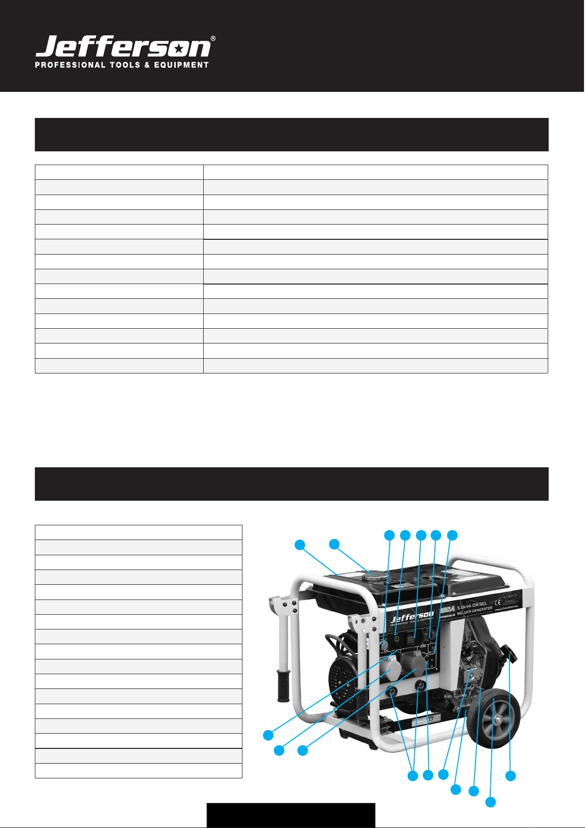
EQUIPMENT IDENTIFICATION
1. Fuel Tank
2. Fuel Cap
3. Key Ignition
4. Power Light
5. Digital Voltage Meter
6. Circuit Breaker
7. DC Reset
8. Engine / Recoil Handle
9. Wheel
10. Oil Fill / Dipstick
11. Oil Drain Plug
12. Decompression Handle
13. Current Adjustment
14. Welder Sockets
15. AC 230V Output
16. AC 110V Output
17. Voltage Switch
2
3 4 5
9
10
8
11
15
12
1
6 7
13
14
16
17
5
www.jeffersontools.com
USER MANUAL
180A •5.8kVA Diesel Welder Generator
JEFGENDIEWEL180
SAFETY GUIDELINES
Please read and ensure that you understand all of the operating instructions, safety
precautions and warnings in this Instruction Manual before operating or maintaining this
equipment. An accident can often be avoided by recognizing a potentially hazardous
situation before it occurs, and by observing the appropriate safety procedures. Hazards
that must be avoided to prevent bodily injury or machine damage are identied by warnings
on the equipment and in this Instruction Manual. Never use this equipment or modify it
in any way that has not been specically recommended by the manufacturer. Contact a
qualied electrician for advice on any issues relating to electrical safety in your working
environment.
ELECTRICAL SAFETY
Ensure that you check the equipment thoroughly to ensure it is safe and t for purpose before each
use. It is important that you inspect all plugs, sockets, power cables and electrical ttings for wear
and damage and repair or replace any defective components. The risk of electric shock can be
minimised by the correct use of the appropriate electrical safety devices.
• The Electricity at Work Act 1989 includes legislation that places legal implications on employers to ensure
the safety of electrical devices in the workplace. The regulations dictate that all portable equipment must be
inspected regularly and tested to ensure that it is safe for use. 'Portable equipment' means any electrical item
that can be moved and this is often referred to as Portable Appliance Testing (PAT). PAT testing should be
carried out regularly on this equipment by trained, authorised personnel, as required by the legislation.
• The Health and Safety at Work Act 1974 states that it is the responsibility of the owner of electrical appliances
to ensure that both the equipment and working environments are maintained to ensure safe operation at all
times.
• Check that all equipment cables are secure, correctly insulated, free from damage, and protected against short
circuit and overload before connecting to the power supply. Do not use worn or damaged cables, plugs, sockets
or other ttings.
• Do not use the generator in damp / wet conditions.
EQUIPMENT SAFETY
• The exhaust gas is poisonous, never use a generator indoors or in an attached garage. Always run your
generator outdoors in a well-ventilated area. Keep the generator at least 1 meter (3 feet) away from buildings and
other equipment during operation.
• Place generator on level ground to operate.
• The load must be kept within rating stated on generator rating plate, overloading will damage the unit or shorten
its life.
• Running the engine at excessive speeds is dangerous and will damage the engine.

6www.jeffersontools.com
USER MANUAL
180A •5.8kVA Diesel Welder Generator
JEFGENDIEWEL180
EQUIPMENT SAFETY (continued)
• Do not tamper with parts, which may increase or decrease the governed speed.
• When using extension cords, please make sure they are grounded with sufcient wire gauge for the application.
Heavy-duty outdoor rated cords will handle household appliance loads.
• The exhaust system gets hot enough to ignite some materials. Do not operate the engine near combustible
materials.
• Do not store fuel indoors or try to refuel a generator while it is still running. Clean up any spilled fuel before
restarting the engine.
• The mufer becomes very hot during operation and remains hot for a while after stopping the engine. Be careful
not to touch the mufer while it is hot. Let the engine cool before storing the generator indoors.
• Turn off all equipment powered by the generator before shutting down your generator.
• To prevent electric shock or re, never use the machine in rain or snow or connect the generator to a live circuit.
• Do not connect the generator to another power supply outlet.
• Protection against electrical shock depends on circuit breakers specically matched to the generating set. If the
circuit breakers require replacement they must be replaced with a circuit breaker having identical ratings and
performance characteristics.
• Ensure the generator does not have any damaged hoses, loose or missing clamps, damaged tank or cap before
use. All defects should be corrected before use.
• To prevent surging that may possibly damage equipment, do not allow the engine to run out of fuel when
electrical loads are applied.
• Before transporting the generator ensure that all the fuel is drained to prevent leakage.
• Unit must meet operating speed before electrical loads are connected. Always disconnect any loads before
turning off the generator.
• Keep children and pets away from the generator at all times.
• The installation and major repair of the generator should only be carried out by trained and fully qualied
engineers.
• Ensure appropriate ear protection is worn when working in close proximity to the generator.
• When using extension cables or mobile electric net use the following guidelines:
Cable Diameter Maximum Length
1.5 60m
2.5 100m
WARNING:
• Do not cover the unit when in use.
• The unit should be earthed using 4mm diameter grounding wire.
• Do not use the generator in wet or damp conditions.
• Store the generator in well-ventilated area with an empty fuel tank.

7
www.jeffersontools.com
USER MANUAL
180A •5.8kVA Diesel Welder Generator
JEFGENDIEWEL180
CHECKING THE GENERATOR PRIOR TO USE
•Check the fuel level and top up with diesel fuel if necessary. Do not overll the fuel tank (there should be no
fuel in the ller neck).
• After refuelling make sure the tank cap is closed properly and securely. Be careful not to spill fuel when refuelling
and clean up any spilled or excess fuel. Spilled fuel or fuel vapour can ignite when the engine
is started.
• The generator has a maximum fuel capacity of 15 Litres
• Do not fill above the fuel filter top.
• Check the engine oil level and top up if necessary as shown in Fig.1.
STARTING THE GENERATOR
Note: To make it easier to start the generator in cold temperatures
remove the oil plug and add 2cc of engine oil before starting.
1. Warm up the engine without the load for about 3 minutes.
2. Open the Fuel Cock.
Recoil Start:
3. Put the starting switch into the "RUN" position.
4. Hold the starting/recoil handle loosely and pull the cord out it until you
feel resistance - then return it slowly.
Key Start:
5. Turn the ignition key to the "Start" position.
CONNECTING EQUIPMENT TO THE GENERATOR
1. Connect the equipment you want to use to the AC socket.
Note: Do not exceed the load limit of the specied maximum AC output.
2. Do not connect the generator to the household network as this may
result in damage to the generator itself or to other electrical appliances
in your home.
Fig.1
WARNING:
• Make sure there is no air in the fuel pipe when using the unit for the rst time, starting the
unit or refuelling an empty tank. You can drain away air by loosening the connection
between the injection pump and pipeline then drain the air until the fuel comes out.
• Do not loosen or adjust either the engine speed limit bolt or fuel injection limit bolt. These
have been set to their optimum settings before leaving the factory.
• Never pull out the start handle when the engine is running. This is dangerous and can
damage the engine.
8www.jeffersontools.com
USER MANUAL
180A •5.8kVA Diesel Welder Generator
JEFGENDIEWEL180
STOPPING THE GENERATOR
1. Before stopping the generator, allow it to run for approximately 3 minutes with no consumers so that it can "cool
down".
2. Turn off the circuit breaker.
3. Turn the key/ignition switch to the "OFF" position.
4. Turn the fuel cock lever to the "CLOSED" position.
TRANSPORTATION AND STORAGE
• When transporting the generator, ensure the starting switch is set to the "OFF" position and that the fuel valve is
set to the "CLOSED" position.
• Keep the generator level to prevent fuel spillage. Fuel vapour or spilled fuel may ignite. Touching a hot engine can
cause serious burns or res.
• Let the engine cool before transporting or storing the generator.
• Make sure not to drop or strike the generator when transporting. Do not place heavy objects on top of the
generator during transit, storage or operation.
OPERATING ENVIRONMENT
This unit can generate rated output under the following conditions:
Altitude Ambient Temperature Relative Humidty
0m +20º 60%
The Generator should work in low output under the following conditions:
Altitude Ambient Temperature Relative Humidty
>1000m >40º90%

9
www.jeffersontools.com
USER MANUAL
180A •5.8kVA Diesel Welder Generator
JEFGENDIEWEL180
MAINTENANCE
The chart below indicates the maintenance checks you should make on your generator parts and the frequency that
these checks should generally be carried out. Note: You can contact your nearest Jefferson dealer for help and
advice and a full list of replacement parts.
Daily 20 Hours Usage 50 Hours Usage 100 Hours Usage 300 Hours Usage
Engine oil check ○
Replace engine oil ○ ○
Check air cleaner ○
Wash the air cleaner ○
Oil filter cup ○
Oil filter ○
Spark plug ○
Valve clearance ○
Clean cylinder cover wash
Fuel tank wash Wash regularly replace every three years
Check the battery and
electrolyte levels Before use
Notes:
• Checking and the engine oil: With generator on level ground: remove the oil ller cap and dipstick clean with a
clean cloth. Insert the dipstick back into the oil lter hole without turning - remove and check that the oil level is
between the minimum and maximum indicators. If level is low rell to the maximum level mark.
●Checking the fuel level: With generator on level ground: open the fuel tank cap. Check the fuel level. If level is low
refuel up to the red marker on the fuel lter. Put the fuel cap back on.
WARNING:
• Ensure that any electrical equipment is disconnected from the generator before carrying
out any maintenance work on the generator.
• The circuit breaker should be in the "OFF" position before maintenance.
• The unit should be eatherd at all times.
10 www.jeffersontools.com
USER MANUAL
180A •5.8kVA Diesel Welder Generator
JEFGENDIEWEL180
TROUBLESHOOTING
Symptom Possible Cause Action
Engine won't start
Not enough fuel oil Add fuel - see section "Checking Generator
Prior to Use"
Fuel nozzle cannot inject fuel or there
is not enough fuel
Repair the fuel injector
The speed control lever is not in the
"Run" position
Move the lever to the "Run" position
Lubricant oil level is too low Check that the oil level is topped up and sits
between the upper and lower level markers
Not enough speed or force used on
the
starter/recoil handle
See section "Starting the Generator"
The fuel nozzle is blocked or dirty Clean tthe fuel nozzle
Generator fault
Circuit breaker is not closed Turn the circuit breaker to the "On" position
Poor or faulty socket connection Adjust the socket feet
The rated generator speed cannot be
obtained
Adjust to rated speed
Carbon brush is faulty or worn Replace the carbon brush
AVR is depreciated Replace the AVR
Parts & Servicing
For Jefferson approved replacement parts contact your
nearest dealer or contact Jefferson tools
Telephone: +44 (0)1244 646 048
Fax: +44 (0)1244 241 191
Email: [email protected]

11
www.jeffersontools.com
USER MANUAL
180A •5.8kVA Diesel Welder Generator
JEFGENDIEWEL180
CIRCUIT / WIRING DIAGRAM

12 www.jeffersontools.com
USER MANUAL
180A •5.8kVA Diesel Welder Generator
JEFGENDIEWEL180
PARTS DIAGRAM - GENERATOR

13
www.jeffersontools.com
USER MANUAL
180A •5.8kVA Diesel Welder Generator
JEFGENDIEWEL180
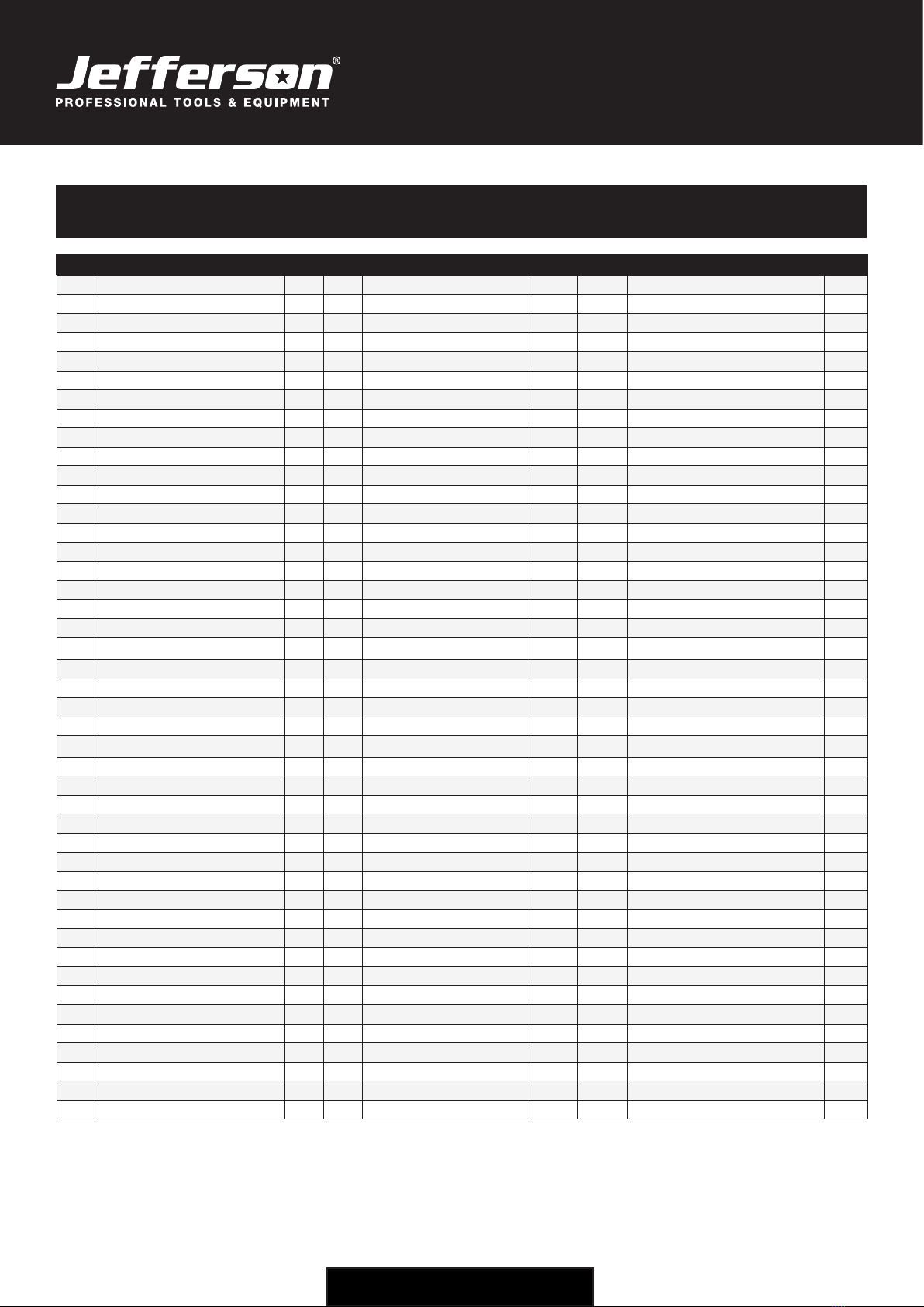
PARTS LIST - GENERATOR
# Description Qty # Description Qty
1Diesel Engine 1 40 Filter 1
2Rectier Support 1 41 Filter Gasket 1
3Rectier 4 42 Gasket B 1
4Mufer Gasket 1 43 Gasket 1
5Mufer 1 44 Screw M5×8 3
6Flat Washer Ø8 1 45 Fuel Tank Switch 1
7Spring Washer Ø8 1 46 Nut M6 2
8Nut M8 2 47 Clap Ø12 2
9Bolt M8×20 2 48 Fuel Pipe Ø7.5×13mm 0.3
10 Alternator 2 49 Clap Ø8 4
11 Bolt M8×33.5 1 50 Fuel Pipe Ø4.5mm 0.55
12 Avr Support 4 51 Top Cover 1
13 Avr 16 52 Frame Candle 1
14 Nut M5 14 53 Battery (12v 20AH) 1
15 Bolt M5×25 18 54 Battery Holder Retractor 2
16 Bolt M8×12 1 55 Fixed Plate 1
17 Base Of Frame 6 56 Nut M6 2
18 Bolt M10×40 4 57 Battery Wire, Red 1
19 Shock Absorbing 1 58 Battery Wire, Black 1
20 Flat Washer Ø10 1 59 Control Pannel 1
21 Spring Washer Ø10 1 60 Screw M6×16 4
22 Nut M10 2 61 Welding Sockets (Red) 1
23 Bolt M6×14 1 62 Welding Sockets (Black) 1
24 Spring Washer Ø6 2 63 Underlay Bracket 1
25 Flat Washer Ø6 4 64 Shock Absorbing Pad 2
26 Tooth Washer Ø6 2 65 Axle 2
27 Grounding Wire 4 66 Wheel 2
28 Tank 1 67 Nut M12 2
29 Fuel Tank Gauge 1 68 Handle Fixed Base 1
30 Fuel Tank Cap 1 69 Bolt M8×45 2
31 Filter 1 70 Bolt M8×45 4
32 Bolt M6×25 1 71 Nut M8 6
33 Flat Washer Ø6 1 72 Buckle 2
34 Air Hood Sleeve 1 73 Handle 2
35 Anti Vibration Block 1 74 Handle Sleeve 2
36 Nut M6 4 75 Handle Fixed Base 1
14 www.jeffersontools.com
USER MANUAL
180A •5.8kVA Diesel Welder Generator
JEFGENDIEWEL180
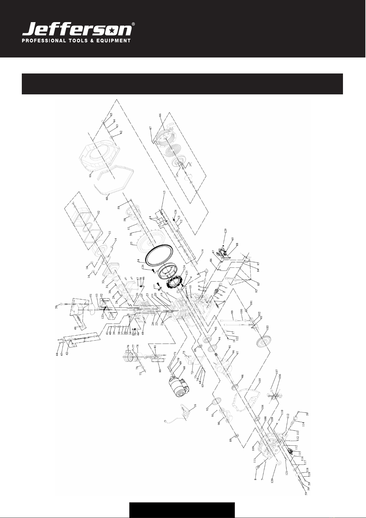
PARTS DIAGRAM - ENGINE
15
www.jeffersontools.com
USER MANUAL
180A •5.8kVA Diesel Welder Generator
JEFGENDIEWEL180
# Description Qty # Description Qty # Description Qty
1Drain Plug 1 45 Valve Lock Clamps 2 89 Bearing 6203 2
2Drain Plug Gasket 2 46 Valve Adjust Cushion Block 2 90 Balance Shaft 1
3Diesel Drain Pipe 1 47 Fuel Injector 1 91 Flat Key 5x5x7 1
4Oil Sealing B3550 1 48 Fuel Injector Platen 1 92 Balance Gear 1
5Crankcase 1 49 Nut M6 2 93 Bearing 6308 1
6Fuel Capacity Controller 1 50 Cylinder Head Nut (Long) 2 94 Balance Shaft Transmission Gear 2
7O-Type Ring 26x3.55g 2 51 Cylinder Head Nut Washer 4 95 Flat Key 5x5x14 1
8Oil Distick(Yellow) 2 52 Cylinder Head Nut (Short) 2 96 Crankshaft V2 2
9Needle Bearing 7941/8 2 53 Stud M8x34 2 97 Flat Key 5x5x12 1
10 Fuel Injection Pump Studs - Short 1 54 Cylinder Head Cover 1 98 Crankshaft Timing Gear 1
11 Fuel Injection Pump Studs - Long 2 55 Bolt M6x70 3 99 Valve Tappet 1
12 Fuel Injection Pump Sealing Board Gasket 1 56 Cylinder Head Cover Gasket 1 100 Valve Lifter 2
13 Fuel Injection Pump Sealing Board 1 57 Rocker Arm 1 101 Needle Bearing 37941/15 1
14 Tooth Flange Nut M6 5 58 Rocker Arm Bolt M8x50 2 102 Camshaft 1
15 Fuel Injection Pump Assy 1 59 Flywheel Gear 1 103 Camshaft Timing Gear 1
16 High Pressure Fuel Pipe 1 60 Flywheel 1 104 Bearing 6207 2
17 Thrust Pad 1 61 Flywheel Nut Washer 1 105 Crankcase Cover Gasket 2
18 Bolt M8x12 1 62 Flywheel Nut 1 106 Oil Pump Gear 1
19 Cylinderhead Sealing 1 63 Starting Sleeve 1 107 Speed Governing Push Dish 1
20 Cylinderhead Studs (Long) 2 64 Bolt M6x12 8 108 Sliding Bearing 1
21 Cylinderhead Studs (Short) 2 65 Wind Hood Shock Pad 0.985 109 Pin8x12 1
22 Pin 4x8 4 66 Wind Hood (Black) 1 110 Oil Absorption Pipe 1
23 Inlet Valve 1 67 Wind Hood Shockcover 4 111 Crankcase Cover 1
24 Outlet Valve 1 68 Bushing 10×10 4 112 Aluminum End Cap Ø8 1
25 Cylinderhead 1 69 Washer 6 5 113 O Ring 20×2.65f 1
26 Stud M6x75 2 70 Bolt M6x22 6 114 Oil Filter 2
27 Inlet Gasket 1 71 Recoil Starter Assy (Black) 1 115 Oil Pressure Alarm 1
28 Inlet Pipe 1 72 Bolt M6*8 4 116 Pin 4x8 3x16 1
29 Bolt M6x28 3 73 Electronic Starter 1 117 Oil Pump 3
30 Air Cleaner Bolt 1 74 Plain Washer 10 2 118 O Ring 34.5×1.8g 1
31 Air Filter Gasket 1 75 Spring Washer 10 6 119 Oil Pump Cover 1
32 Air Filter Shell 1 76 Bolt M10*35 2 120 Oil Sealing B3550 1
33 Air Filter 1 77 Arrow Board 1 121 Bolt M8x33.5 1
34 Insulation Cladding 1 78 Damping Mat 1 122 Washer 8 1
35 Stud M6x55 2 79 Bush 1 123 Easticity Washer 8 1
36 Valve Spring Washer 2 80 Cushion Strip 1 124 Fly Wheel Generator 1
37 Oil Sealing B0711 1 81 Piston Ring 1 125 Bolt M6*12 1
38 Valve Spring 2 82 Piston Pin Circlip 23 2 126 Bolt M6*18 16
39 Valve Spring Seat 2 83 Piston 1 127 Press Board 3
40 Valve Lock Clamps 2 84 Piston Pin 1 128 Nut M6 2
41 Valve Adjust Cushion Block 2 85 Connect Rod Assy 1 129 Bolt M6x14 1
42 Fuel Injector 1 86 Connect Rod Bearing 1 130 Fuel Injection Pump Gasket 1
43 Fuel Injector Platen 1 87 Fork Shaft Washer 1.5mm 1 131 Cylinderhead Gasket 1
44 Nut M6 2 88 Fork Assy 1
PARTS LIST - ENGINE

16 www.jeffersontools.com
USER MANUAL
180A •5.8kVA Diesel Welder Generator
JEFGENDIEWEL180
LIMITED WARRANTY STATEMENT
Jefferson Professional Tools & Equipment, or hereafter "Jefferson" warrants its customers that its products will be free of defects in workmanship
or material. Jefferson shall, upon suitable notication, correct any defects, by repair or replacement, of any parts or components of this product
that are determined by Jefferson to be faulty or defective.
This warranty is void if the equipment has been subjected to improper installation, storage, alteration, abnormal operations, improper care, service
or repair.
Warranty Period
Jefferson will assume both the parts and labour expense of correcting defects during the stated warranty periods below.
All warranty periods start from the date of purchase from an authorised Jefferson dealer. If proof of purchase is unavailable from the end user, then
the date of purchase will be deemed to be 3 months after the initial sale to the distributor.
1 Year
• JEFGENDIEWEL180 - 180A 5.8kVA Diesel Welder Generator (Key Start)
90 Days
• All replacement parts purchased outside of the warranty period
Important: All parts used in the repair or replacement of warranty covered equipment will be subject to a minimum of 90 days cover or the
remaining duration of the warranty period from the original date of purchase.
Warranty Registration / Activation
You can register and activate your warranty by visiting the Jefferson Tools website using the following address:
www.jeffersontools.com/warranty and completing the online form. Online warranty registration is recommended as it eliminates the need to
provide proof of purchase should a warranty claim be necessary.
Warranty Repair
Should Jefferson confirm the existence of any defect covered by this warranty the defect will be corrected by repair or replacement at an
authorized Jefferson dealer or repair centre.
Packaging & Freight Costs
The customer is responsible for the packaging of the equipment and making it ready for collection. Jefferson will arrange collection and
transportation of any equipment returned under warranty. Upon inspection of the equipment, if no defect can be found or the equipment is not
covered under the terms of the Jefferson warranty, the customer will be liable for any labour and return transportation costs incurred.
These costs will be agreed with the customer before the machine is returned.
*Jefferson reserve the right to void any warranty for damages identified as being caused through misuse
Warranty Limitations
Jefferson will not accept responsibility or liability for repairs made by unauthorised technicians or engineers. Jefferson's liability under this
warranty will not exceed the cost of correcting the defect of the Jefferson products.
Jefferson will not be liable for incidental or consequential damages (such as loss of business or hire of substitute equipment etc.) caused by
the defect or the time involved to correct the defect. This written warranty is the only express warranty provided by Jefferson with respect to its
products.
Any warranties of merchantability are limited to the duration of this limited warranty for the equipment involved.
Jefferson is not responsible for cable wear due to flexing and abrasion. The end user is responsible for routine inspection of cables for possible
wear and to correct any issues prior to cable failure.

17
www.jeffersontools.com
USER MANUAL
180A •5.8kVA Diesel Welder Generator
JEFGENDIEWEL180
Claiming Warranty Coverage
The end user must contact Jefferson Professional Tools & Equipment (Tel: +44 (0) 1244 646 048) or their nearest authorised Jefferson dealer where
final determination of the warranty coverage can be ascertained.
Step 1 - Reporting the Defect
Online Method:
• Visit our website www.jeffersontools.com/warranty and complete the Warranty Returns form. You can complete the form online and submit it
to us directly or download the form to print out and return by post.
Telephone Method:
Contact your Jefferson dealer or sales representative with the following information:
• Model number
• Serial number (usually located on the specification plate)
• Date of purchase
A Warranty Returns form will be sent to you for completion and return by post or fax, together with details of your nearest authorised Jefferson
repair centre. On receipt of this form Jefferson will arrange to collect the equipment from you at the earliest convenience.
Step 2 - Returning the Equipment
It is the customer's responsibility to ensure that the equipment is appropriately and securely packaged for collection, together with a copy of
the original proof of purchase. Please note that Jefferson cannot assume any responsibility for any damage incurred to equipment during
transit. Any claims against a third party courier will be dealt with under the terms & conditions of their road haulage association directives.
NOTE: Jefferson will be unable to collect or process any warranty requests without a copy of the original proof of purchase.
Step 3 - Assessment and Repair
On receipt, the equipment will be assessed by an authorised Jefferson engineer and it will be determined if the equipment is defective and in need
of repair and any repairs needed are covered by the warranty policy. In order to qualify for warranty cover all equipment presented must have been
used, serviced and maintained as instructed in the user manual.
Where repair is not covered by the warranty a quotation for repair, labour costs and return delivery will be sent to the customer (normally within 7
working days).
NOTE: If the repair quotation is not accepted Jefferson Professional Tools & Equipment will invoice 1 hour labour time at £30 per hour plus
return carriage costs (plus VAT).
In cases where no fault can be found with the equipment, or, if incorrect operation of the equipment is identified as the cause of the problem, a
minimum of 1 hour labour at £30 per hour plus carriage costs will be required before the equipment will be despatched back to the customer.
Any equipment repaired or replaced under warranty will normally be ready for shipment back to the customer within 7 working days upon receipt
of the equipment at an authorised Jefferson Repair centre (subject to part availability). Where parts are not immediately available Jefferson will
contact you with a revised date for completion of the repair.
General Warranty Enquiries
For any further information relating to Jefferson warranty cover please call +44 (0) 1244 646 048 or send your enquiry via email to warranty@
jeffersontools.com
Disclaimer:
The information in this document is to the best of our knowledge true and accurate, but all recommendations or suggestions are made without
guarantee. Since the conditions of use are beyond their control, Jefferson Tools® disclaim any liability for loss or damage suffered from the use of
this data or suggestions. Furthermore, no liability is accepted if use of any product in accordance with this data or suggestions infringes any patent.
Jefferson Tools® reserve the right to change product specifications and warranty statements without further notification. All images are for
illustration purposes only.
18 www.jeffersontools.com
USER MANUAL
180A •5.8kVA Diesel Welder Generator
JEFGENDIEWEL180
EC DECLARATION OF CONORMITY
We, Jefferson Professional Tools & Equipment, as the authorised European
Community representative of the manufacturer, declare that the following equipment
conforms to the requirements of the following:
Directive / Standard / Regulation Description:
2000/14/EC (as amended) Noise Emission in the Environment by Equipment for Use Outdoors
2006/42/EC (as amended) Machinery Directive
(EU) 2016/1628 (as amended) Non Road Mobile Machinery Directive
Equipment Category: Power Generator (Item 45)
Product Name/Model: JEFGENDIEWEL180 -
180A 5.8kVA Diesel Welder Generator (Key Start)
Measured Sound Power Level:
Guaranteed Sound Power Level:
103dB
103dB
The conformity assessment procedure followed was in accordance
with Annex VI of the Outdoor Noise Directive
EU type-approval number: e24 *2016 /1628 *2018 /989EC1/D*0145*00
Signed by: Stephen McIntyre
Position in the company: Operations Director
Date: 06 October 2020
Technical file holder's address as shown below
Name and address of manufacturer
or authorised representative:
Jefferson Tools, Herons Way, Chester Business Park,
Chester, United Kingdom, CH4 9QR
Telephone: +44 (0)1244 646 048 Fax: +44 (0)1244 241 191
Email: [email protected]


Jefferson Tools,
Herons Way,
Chester Business Park,
Chester,
United Kingdom,
CH4 9QR
Tel. +44 (0)1244 646 048
Email: [email protected]
IMPORTANT! SAFETY FIRST!
Before attempting to use this product please read
all the safety precautions and operating instructions
outlined in this manual to reduce the risk of fire,
electric shock or personal injury.
www.jeffersontools.com
Table of contents


