Baur SSG 500 User manual
0-1
02/2011
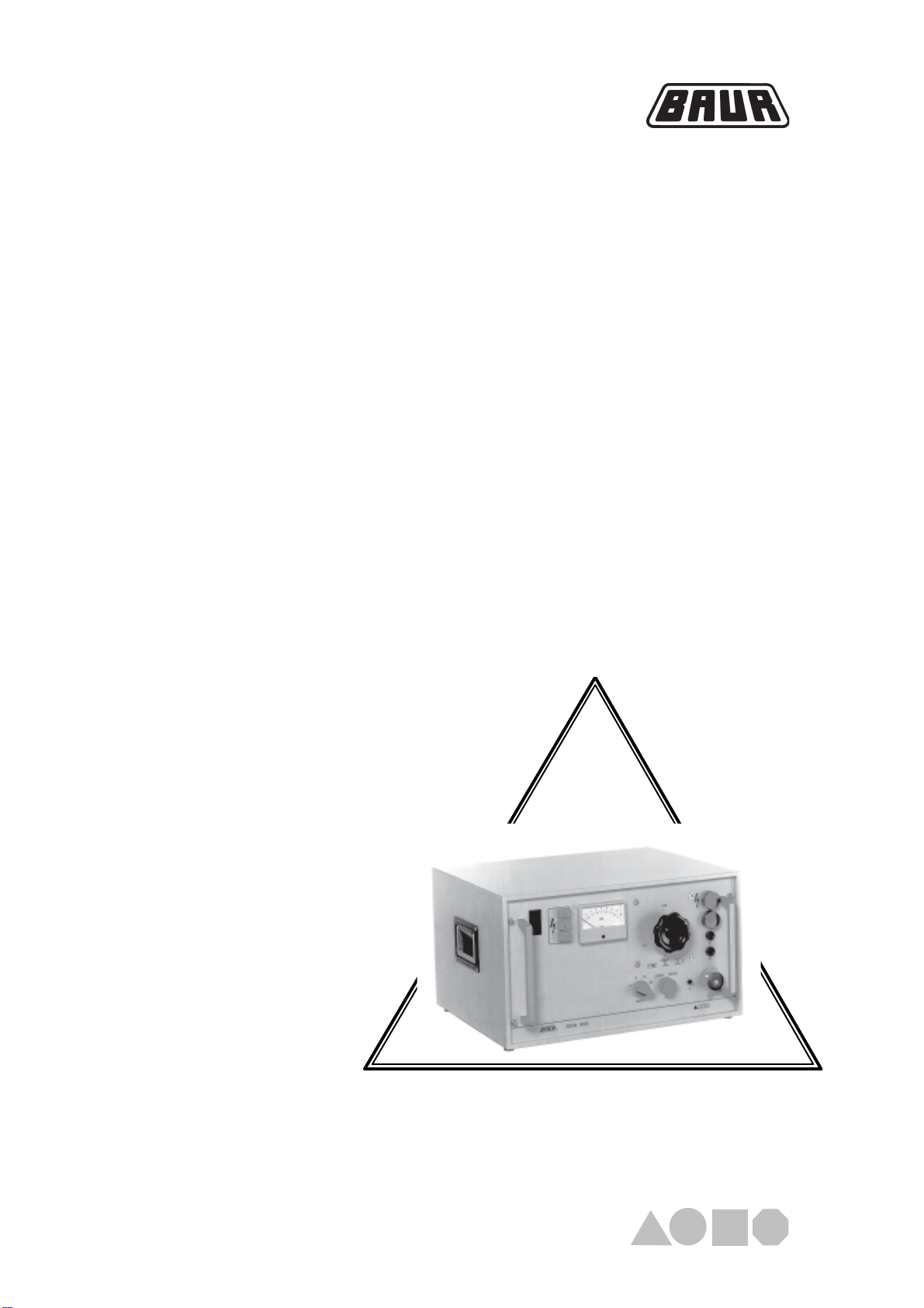
Surge Voltage Generator
SSG 500
Operating Instructions
Ident. Nr. 822-016
BAUR Prüf- und Messtechnik GmbH
Raiffeisenstrasse 8, A-6832 Sulz / Austria
Tel +43 / 55 22 / 49 41-0
Fax +43 / 55 22 / 49 4 13
e-mail: [email protected]
internet: http://www.baur.at

0-2

0-3
© BAUR Prüf- und Messtechnik GmbH,
A-6832 Sulz / Austria
All rights reserved.
No part of this publication may be reproduced, transmitted, stored
in a data processing system or translated into another language
without the written permission of BAUR / Sulz, Austria.
In the interest of our customers we reserve the rights for
modifications due to technical progress.
Illustrations, descriptions and delivery content are therefore not
binding.
For fast finding of important information the corresponding text
passages are marked with symbols (symbols not stated here are
self-explaining).
More and special information concerning the respective subject are
available from BAUR.
Important unit information!
In any case, read carefully!
Important information text.
The surge voltage generator SSG 500 is built in accordance with
today's state of engineering and is safe to operate. Individual
components and the finished unit are inspected continually by our
qualified staff within the framework of our Quality Assurance
Provisions. Each unit is subjected to thorough testing prior to
shipment.
Safety Precautions
Guide to this Operating Instruction
Observe
info signs!
Copyright
BAUR Prüf- und Messtechnik GmbH, Raiffeisenstrasse 8
A-6832 Sulz / Austria
or refer to your nearest BAUR representative.
Tel +43 / 55 22 / 49 41-0
Fax +43 / 55 22 / 49 41-3
☞
Preface This manual contains all information necessary for the correct
handling and use of the surge voltage generator SSG 500. Before
using the surge voltage generator, please read carfully this
Operating Instruction:
If you have any question, please contact directly:
Guide to this Operating Instruction, Copyright, Preface
Subject to modification!

0-4
It is imperative to every person who is involved with the installation,
start-up, operation and maintenance of the SSG 500 to have read
and understood the complete Operating Instruction.
It is the responsibility of the customer to ensure that only authorized
persons may be allowed to use the surge voltage generator
SSG 500.
The user
- is qualivied and properly instructed and has the necessary
experience.
- knows the relevant standards, accident prevention rules and
operating conditions.
- is able to carry out the necessary operations and is aware of
the possible dangers involved.
- must immediately inform his superior about any conditions of
the unit that coult affect safety.
The surge voltage generator SSG 500 is used for cable fault
location at layed power cables.
Any other or additional use is deemed to be in contravention of the
intended use. The manufacturer shall not be liable for damage
resulting from any such us. In such a case the risk shall be borne
solely by the user.
The local safety and accident prevention regulations are
always applicable to the operation of the surge voltage
generator unit.
Especially the surge voltage generators may not be used in
potentially explosive atmosphere or at test objekts which are
in service.
Garantie
Safety Precautions, Continued
At the customer's written request we undertake to repair or
replace at our discretion and as quickly as possible allparts that
become faulty or useless as the demonstrable result of poor
material, faulty design or defective execution.
We bear the costs for repairs and replaced parts, exclusive
transportation of the goods, packing and insurance.
The 12 month warranty time starts with delivery.
We shall bear the costs of any faulty parts requiring replacement,
but not the costs of transport to us an back to the customer, not the
costs of packing and insurance! We shall not be liable for any
damage resulting from normal wear and tear, improper handling,
non-observance of Operating Instruction and safety regulations. We
shall also refuse to accept any liability if the customer carries out
repairs or changes to the unit himself or has others carry out them!
The warranty does not cover damage in transit, batteries, fuses and
any readjustments in accordance with the Operating Instruction!
We draw attention in addition to the "General Terms of Sales and
Delivery".
Please read now and
avoid damage and injury later!
Sicherheitshinweise, Garantie
12 month warranty time
Only authorized personnel!
Use the SSG 500
unit as directed!
☞

0-5
Contents
1. Product Information .........................................................................1-1
Overview ......................................................... 1-1
Design and function ........................................ 1-2
Display and operating elements...................... 1-3
Technical data ................................................. 1-5
2. Packing and Delivery .......................................................................2-1
Damage during transport ................................ 2-1
3. Setting into operation ......................................................................3-1
Overview ......................................................... 3-1
Modes ............................................................. 3-2
Connection of instrument ................................ 3-4
Connection of mains ....................................... 3-6
Switch on ........................................................ 3-7
Switch off ........................................................ 3-8
EMERGENCY SWITCHING OFF ................... 3-9
4. Maintenance......................................................................................4-1
Overview ......................................................... 4-1
Safety precautions .......................................... 4-2
Fuses .............................................................. 4-2
Checking the discharge unit............................ 4-3
Replacing high voltage connection lead ......... 4-3
5. Options, Accessories and Ordering Information...........................5-1
Overview ......................................................... 5-1
Options ........................................................... 5-2
Accessories .................................................... 5-2
Ordering information ....................................... 5-3
Contents

0-6
○○○○○○○○○○○○○○○○○○○○○○○○○○○○○○○○○○○○○○
○○○○○○○○○○○○○○○○○○○○○○○○○○○○○○○○○○○○○○
○○○○○○○○○○○○○○○○○○○○○○○○○○○○○○○○○○○○○○
○○○○○○○○○○○○○○○○○○○○○○○○○○○○○○○○○○○○○○
○○○○○○○○○○○○○○○○○○○○○○○○○○○○○○○○○○○○○○
○○○○○○○○○○○○○○○○○○○○○○○○○○○○○○○○○○○○○○
○○○○○○○○○○○○○○○○○○○○○○○○○○○○○○○○○○○○○○
○○○○○○○○○○○○○○○○○○○○○○○○○○○○○○○○○○○○○○
○○○○○○○○○○○○○○○○○○○○○○○○○○○○○○○○○○○○○○
○○○○○○○○○○○○○○○○○○○○○○○○○○○○○○○○○○○○○○
○○○○○○○○○○○○○○○○○○○○○○○○○○○○○○○○○○○○○○
○○○○○○○○○○○○○○○○○○○○○○○○○○○○○○○○○○○○○○
○○○○○○○○○○○○○○○○○○○○○○○○○○○○○○○○○○○○○○
○○○○○○○○○○○○○○○○○○○○○○○○○○○○○○○○○○○○○○
○○○○○○○○○○○○○○○○○○○○○○○○○○○○○○○○○○○○○○
○○○○○○○○○○○○○○○○○○○○○○○○○○○○○○○○○○○○○○
○○○○○○○○○○○○○○○○○○○○○○○○○○○○○○○○○○○○○○
○○○○○○○○○○○○○○○○○○○○○○○○○○○○○○○○○○○○○○
○○○○○○○○○○○○○○○○○○○○○○○○○○○○○○○○○○○○○○
○○○○○○○○○○○○○○○○○○○○○○○○○○○○○○○○○○○○○○
○○○○○○○○○○○○○○○○○○○○○○○○○○○○○○○○○○○○○○
○○○○○○○○○○○○○○○○○○○○○○○○○○○○○○○○○○○○○○
○○○○○○○○○○○○○○○○○○○○○○○○○○○○○○○○○○○○○○
Notes
Notes
1-1
1. Product Information
1. Product Information
Overview
In this section you will find all necessary product information for the
Surge Voltage Generator SSG 500.
This section covers the following subjects:
Subject Page
Design and function 1-2
Display and operating elements 1-3
Technical data 1-5

1-2
1. Product Information
Instruments of the SSG family are rack mounting units in the 19"
format. Various operating and indicating elements are mounted on
the front panel, connecting elements are mounted on the back-
plate. The instruments contain their own high voltage generator,
impulse-proof surge capacitors, automatic and manually triggered
spark gaps and an internal discharge device.The instrument control
contains the necessary safety circuits also for connection of an
external Emergency Stop unit and for the operation of the SA 32
option.
The mains voltage is applied to the primary winding or a tapping of
the primary winding of the high voltage transformer via the
reduction switch (13), depending on its position.The secondary
windings of the high voltage transformer features four high voltage
windings, fully isolated of each other, which are connected each to
a partial capacitor through a half-wave rectifier. With the aid of the
range selector switch (6) the partial capacitors become connected
to each other. The series connection allows a maximum voltage of
16kV. The connection of two capacitors each in series and parallel
allows a maximum 8kV and the complete parallel connection of the
capacitors leads to a maximum voltage of 4kV. In this configuration
it can be accomplished, that the maximum surge energy of the
capacitors is available in three voltage ranges. Through the
selection of the three ranges 3 / 6 / 12kV using the reduction switch
(13) 56% of the surge energy are available.
The Surge Voltage Generator SSG 500 is designed in such a way
that it generates pulse-shaped voltages with a steep edge, which
should start to break down the cable fault. The high surge current
flowing at the cable fault generates electromagnetic and acoustic
waves which radiate from the cable fault. These waves can be
detected on the ground surface with appropriate detection devices
such as search coils or ground microphones. The SSG 500
however can also be implemented for pre-location. In this case it is
used as burn down device for short time operation or it can be used
with an echometer and the SA 32.
Design and function
Design
High voltage generation
Function

1-3
1. Product Information
Display and operating elementes
Front panel
1 Mains switch as overload protection switch with thermal
release
2 Pushbutton switch „Ready to switch on“ ( )
3 Pushbutton switch „H.V. On“ (I ) with warning lamp for
high voltage clearance. The indicator lamp serves as
feedback for the operating state „IN OPERATION“
4 Pushbutton switch „H.V. Off“ ( ) returns the instrument
into the operating condition "READY FOR OPERATION“.
5 Voltmeter of class 1.5 for display of output voltage in kV
6 w 4 / 8 / 16kV
7 Red indicator lamp for feedback of operating condition
„READY TO SWITCH ON“ and „IN OPERATION“
8 Green indicator lamp for feedback of operating condition
„READY FOR OPERATION“
9 Fuse F3 (3,15A slow-blow) for control of lifting magnet and
control of SA 32 (option)
10 Fuse F4 (3,15A slow-blow) for control of lifting magnet and
control of SA 32 (option)
11 EMERGENCY OFF SWITCH pushbutton (lockable) for
activating the EMERGENCY OFF function and to protect
against unauthorized switching on
12 Overload protection switch with thermal and magnetic
tripping
13 Reduction switch for voltage reduction to 3 / 6 / 12 kV
(56% surge energy)
14 Mode selector switch for selecting operating modes „D.C.
operation“, „Zero position“, „Impulse sequence 10/min“,
„Impulse sequence 20/min“.
11
7
8
9
10
14 13 12
1324 56
1-4
1. Product Information
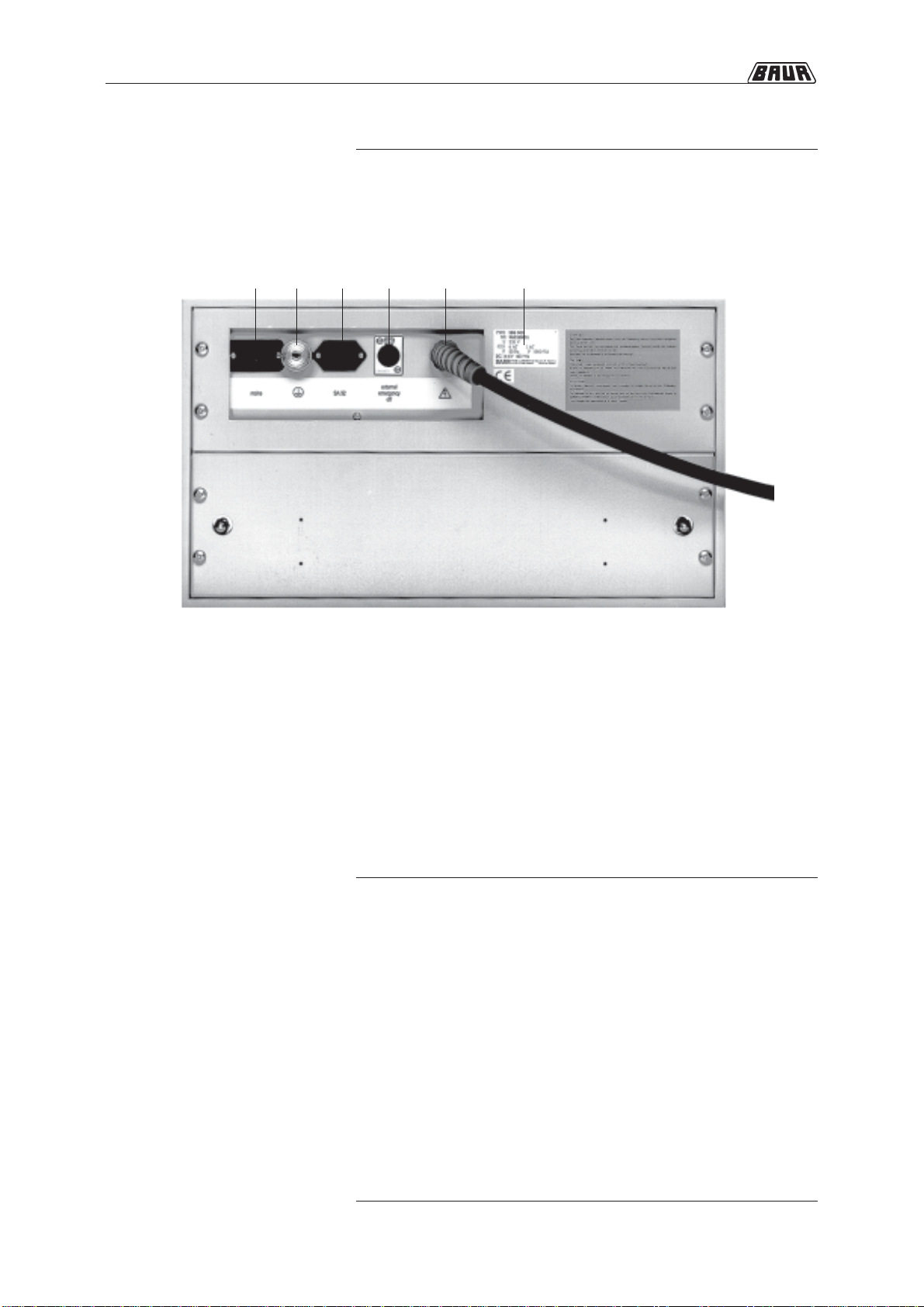
15 Connection socket for external EMERGENCY OFF unit
with jumper plug
16 Connection for mains to SA 32
17 Connection for mains
18 Terminal for connection of protective earth lead
19 Type plate
20 High voltage connecting lead
Backplate
17 15 201618 19

1-5
1. Product Information
SSG 500 unit
Mains voltage see type plate
Mains frequency 45 to 60 Hz
Max. power consumption
(at short ciruit condition) 1.500 VA
Max. output voltage 16 kV
Max. surge energy 512 Ws
Accuracy of kV-meter 1,5 %
Dimensions of housing (W x H x D) 502 x 286 x 390 mm
Weight 48 kg
Technical data

1-6
1. Product Information
○○○○○○○○○○○○○○○○○○○○○○○○○○○○○○○○○○○○○○
○○○○○○○○○○○○○○○○○○○○○○○○○○○○○○○○○○○○○○
○○○○○○○○○○○○○○○○○○○○○○○○○○○○○○○○○○○○○○
○○○○○○○○○○○○○○○○○○○○○○○○○○○○○○○○○○○○○○
○○○○○○○○○○○○○○○○○○○○○○○○○○○○○○○○○○○○○○
○○○○○○○○○○○○○○○○○○○○○○○○○○○○○○○○○○○○○○
○○○○○○○○○○○○○○○○○○○○○○○○○○○○○○○○○○○○○○
○○○○○○○○○○○○○○○○○○○○○○○○○○○○○○○○○○○○○○
○○○ ○○○○○○○○○○○○○○○○○○○○○○○○○○○○○○○○○○○
○○○ ○○○○○○○○○○○○○○○○○○○○○○○○○○○○○○○○○○○
○○○ ○○○○○○○○○○○○○○○○○○○○○○○○○○○○○○○○○○○
○○○ ○○○○○○○○○○○○○○○○○○○○○○○○○○○○○○○○○○○
○○○ ○○○○○○○○○○○○○○○○○○○○○○○○○○○○○○○○○○○
○○○ ○○○○○○○○○○○○○○○○○○○○○○○○○○○○○○○○○○○
○○○ ○○○○○○○○○○○○○○○○○○○○○○○○○○○○○○○○○○○
○○○ ○○○○○○○○○○○○○○○○○○○○○○○○○○○○○○○○○○○
○○○○○○○○○○○○○○○○○○○○○○○○○○○○○○○○○○○○○○
○○○ ○○○○○○○○○○○○○○○○○○○○○○○○○○○○○○○○○○○
○○○ ○○○○○○○○○○○○○○○○○○○○○○○○○○○○○○○○○○○
○○○ ○○○○○○○○○○○○○○○○○○○○○○○○○○○○○○○○○○○
○○○ ○○○○○○○○○○○○○○○○○○○○○○○○○○○○○○○○○○○
○○○ ○○○○○○○○○○○○○○○○○○○○○○○○○○○○○○○○○○○
○○○ ○○○○○○○○○○○○○○○○○○○○○○○○○○○○○○○○○○○
Notes

2. Packing and Shipping
2-1
2. Packing and Shipping
The instruments are shipped in robust cardboard cartons on
wooden pallets. If the instruments are not used immediately, always
keep in closed carton and store in dry rooms!
Complaints concerning damages should be made to us without
delay, using a standard transport damage claims form.
Confirmation of visible damage should immediately be obtained
from the carrier.
The extent and the probable cause of damage should be stated.
If damage is discovered during unpacking, contact the responsible
transportation company immediately. Request a written loss
assessment and make them responsible for the damage!
We also refer to the “General Terms of Sale and Delivery„ of:
Damage during
transport
BAUR Prüf- und Messtechnik GmbH,
A-6832 Sulz / Austria

2. Packing and Shipping
2-2
○○○○○○○○○○○○○○○○○○○○○○○○○○○○○○○○○○○○○○
○○○○○○○○○○○○○○○○○○○○○○○○○○○○○○○○○○○○○○
○○○○○○○○○○○○○○○○○○○○○○○○○○○○○○○○○○○○○○
○○○○○○○○○○○○○○○○○○○○○○○○○○○○○○○○○○○○○○
○○○○○○○○○○○○○○○○○○○○○○○○○○○○○○○○○○○○○○
○○○○○○○○○○○○○○○○○○○○○○○○○○○○○○○○○○○○○○
○○○○○○○○○○○○○○○○○○○○○○○○○○○○○○○○○○○○○○
○○○○○○○○○○○○○○○○○○○○○○○○○○○○○○○○○○○○○○
○○○ ○○○○○○○○○○○○○○○○○○○○○○○○○○○○○○○○○○○
○○○ ○○○○○○○○○○○○○○○○○○○○○○○○○○○○○○○○○○○
○○○ ○○○○○○○○○○○○○○○○○○○○○○○○○○○○○○○○○○○
○○○ ○○○○○○○○○○○○○○○○○○○○○○○○○○○○○○○○○○○
○○○ ○○○○○○○○○○○○○○○○○○○○○○○○○○○○○○○○○○○
○○○ ○○○○○○○○○○○○○○○○○○○○○○○○○○○○○○○○○○○
○○○ ○○○○○○○○○○○○○○○○○○○○○○○○○○○○○○○○○○○
○○○ ○○○○○○○○○○○○○○○○○○○○○○○○○○○○○○○○○○○
○○○○○○○○○○○○○○○○○○○○○○○○○○○○○○○○○○○○○○
○○○ ○○○○○○○○○○○○○○○○○○○○○○○○○○○○○○○○○○○
○○○ ○○○○○○○○○○○○○○○○○○○○○○○○○○○○○○○○○○○
○○○ ○○○○○○○○○○○○○○○○○○○○○○○○○○○○○○○○○○○
○○○ ○○○○○○○○○○○○○○○○○○○○○○○○○○○○○○○○○○○
○○○ ○○○○○○○○○○○○○○○○○○○○○○○○○○○○○○○○○○○
○○○ ○○○○○○○○○○○○○○○○○○○○○○○○○○○○○○○○○○○
Notes
3-1
3. Placing into operation
3. Placing into operation
Overview
In this section you will find all necessary information to put the
Surge Voltage Generator SSG 500 into operation.
This section describes the following subjects:
Subject Page
Modes 3-2
Connection of instrument 3-4
Connection to mains 3-6
Switch on 3-7
Switch off 3-8
Discharge 3-8
EMERGENCY OFF 3-9

3-2
3. Placing into operation
Operating modes
Impulse operation The impulse operation serves first of all for fault locating and is
divided into manual and automatic impulse triggering.The mode
selector switch (14) allows to switch between positions „Zero
position“, „Slow impulse sequence“ and „Fast impulse sequence“
even during operation and under voltage.
Manual impulse triggering is primarily intended for application of the
surge voltage generator in pre- locating, as for example in
connection with the Intercom SA 32 (option) and the echometer. By
applying the secondary impulse method in high resistance faults,
an assessment of the fault distance with one or a few impulse
trigger actions can already be made.
zIf instrument is in operating condition „IN OPERATION“ place
operating mode selector switch (14) from zero position into =
position momentarily and reset again.
Automatic impulse triggering is primarily used for pin-pointing a
cable fault.
The SSG 500 is equipped with a timer coupled to the mains
frequency which allows automatic impulse triggering with impulse
frequencies of 10/min and 20/min. The regularity of the subsequent
impulses serves to better differentiate between the signals of the
fault location and interferences.
zSwitch operating mode selector switch (14) to impulse sequence
10/min or 20/min.
If the instrument is in the operating condition „READY
TO SWITCH ON“ it closes the spark gap automatically
according to the appropriately selected impulse sequence.
Manual impulse triggering
Automatic impulse triggering

3-3
3. Placing into operation
In connection with the Intercom SA 32 (option) with mA-meter the
output current can be measured and be limited by activating the
reduction switch (13). Additionally, there is a possibility to limit the
output current by a high-power resistor.
DC Operation
Fault location
Testing
The Surge Voltage Generator can be put into D.C. operation via the
mode selector switch (14).
zTurn mode selector switch (14) to the fully left position =.
The spark gap will be permanently closed and therefore
connects the high voltage output directly with the surge
capacitor.
In D.C. operation, with the surge capacitors connected, the voltage
is increased until the cable fault breaks down. This mode of
operation is recommended especially for estimating the breakdown
voltage in order to conduct an optimal range selection for the
impulse operation. In combination with the SA 32 option and the
echometer, the D.C. operation can also be implemented in pre-
locating of cable faults.
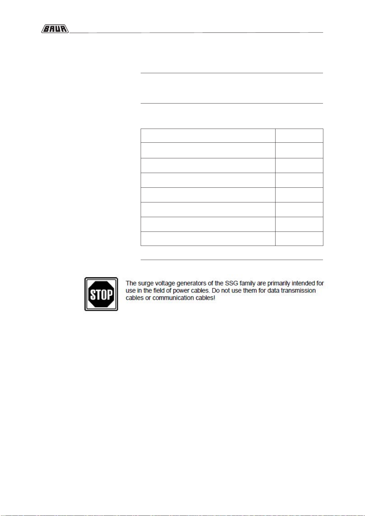
D.C. voltage tests can also be conducted in the D.C. operation.It is
however important that the connected surge capacity, in case of a
breakdown, is discharged through the fault location and that the
surge generator switches to burn down operation. The instrument
protects itself from overloads switching off automatically after a
certain time by the overload protection switch (12). During short-
term operation, maximum output currents can be found during the
burn down process according to the following table.
Range selector switch max. output current (IMAX)
in 4 kV position 480 mA
in 8 kV position 240 mA
in 16 kV position 120 mA

3. Placing into operation
3-4
Connection of instrument
Observe correct position of connection terminals!
(also see Note on page 3-5)
Connection to a single-phase shielded cable
Connection of a three-phase shielded cable
Connection to a three-phase unshielded cable with neutral
1. Rear view of device
2. High voltage connection cable
3. Protective ground cable
4. High voltage connection cable conductor
5. High voltage connection cable screen
6. Station ground
- Protective ground connection
- Operating ground connection
Pulse current flow

3. Placing into operation
3-5
Preparing test object
•Isolate the test object
•Lock against reconnection
•Make sure that zero voltage condition exists.
•Insulate nearby items which are under voltage
•It must be assured that nearby items of the station or cable system under
voltage do not result in breakovers or breakdowns, due to applying surge or
D.C. voltage of the surge generator to the test object.
•Connect all strands in the cable station, with the exception of the fault afflic-
ted strand, to the station earth.
Attention! Wire size and insulating capacity of the cable system must be in
an appropriate relationship to the amplitude of surge voltage and to the
surge energy. Otherwise, overloading to the still intact parts of the system
might occur.
Connecting the protective ground
•Connect the surge voltage generator with the station ground through the
protective ground connection on the rear plate of the device (18)
Attention! Connect the protective ground cable as close to the station
ground connection as possible (see connection examples on page 3-4).
The protective earth lead should be kept as short as possible and must
have low impedance (min. cross section 10 mm², copper).
Connecting the operating ground
The high voltage connection cable screen is used as operating ground.
The operating ground closes the electric circuit and is used for the re-
turn cable of the impulse current!
Connect the operating ground carefully because it must withstand the
full surge current. Observe the correct terminal position!
•Connect the high voltage connection cable screen (operating ground con-
nection) to the station ground. Select the location for the connection of the
screen to the station ground as follows:
- as close as possible to the location where the test object screen is
connected to the station ground and
- as close as possible to the location where the test object conductors
that will not be tested are connected to the station ground (see con-
nection examples on page 3-4

3. Placing into operation
3-6
Estabilshing H.V. connection
•Connect strand of the high voltage connecting lead with the fault afflicted
strand of the test object.
It is very important that all connections are of low resistance as possible.
Bad connections can lead to weldings or contact wear.
•Install external EMERGENCY OFF unit (option) at appropriate location and
plug in the connection plug instead of the jumper plug (15) on back plate of
surge generator.
Connection to mains
Mains operation
•Connect instrument to mains supply using appropriate mains voltage and
minimum fuse rating.
The protective conductor of the mains supply must have the same
potential as the station earth!
Operation with emergency power generator
The generator must have adequate power to meet the maximum power re-
quirements of the instrument (see technical data) without break down of voltage
or frequency, due to its load. Otherwise, it could happen that the instrument will
be switched off automatically.
•Set generator voltage according to mains voltage as indicated on type plate
and connect instrument.
The separate network may not be electrical isolated but must
be connected to protective earth!
Table of contents


