Jefferson JEFPDB0350 User manual

www.jeffersontools.com
FEATURES
User Manual
v.1.1
JEFPDB0350
JEFPDB0350
350W
BENCH
DRILL
Fitted with a heavy duty motor, capable of drilling into
wood, plastics, ceramics and many metals.
Small footprint area for workshop or portable
enough to take to the job.
Manufactured with a steel pillar, with rigid cast iron
head, table, and base to accurate holes.
Smooth and balanced performance
even at high speeds.
Predrilled base holes for mounting onto
a bench or work stand.
Slotted table allows for mounting clamps
and vises for effective work holding.
Fitted with a table height adjustment control
Supplied with a telescopic chuck guard and
a front mounted.
NVR switch for added convenience and safety.
Drilling capacity Ø13mm
Motor power 350W
Chuck capacity 1.5-13mm
Spindle Taper B16
Speeds (50Hz) 620~2620 RPM
Swing 210mm
Spindle travel 50mm
Column diameter Ø46mm
Table size 160 x 160mm
Throat depth 105mm
Height 580mm
SPECIFICATION
IMPORTANT: Please read all of the safety and operatng instructons
carefully before using this product. Please pay particular
attention to all sections of these instructions that display
warning symbols and notices.
IMPORTANT!


……………………………………………………………………………………………………………………………………
……………………………………………………………………………………………………………………………………………
……………………………………………………………………………………………………………………………………………………
……………………………………………………………………………………………………………………………………………
………………………………………………………………………………………………………………………………………………………
………………………………………………………………………………………………………………………………………………………
………………………………………………………………………………………………………………………………………………………
……………………………………………………………………………………………………………………………………………
…………………………………………………………………………………………………………………………………………………………
………………………………………………………………………………………………………………………………………………
……………………………………………………………………………………………………………………………………
…………………………………………………………………………………………………………………………………………
www.jeffersontools.com
User Manual
v.1.1
JEFPDB0350
1. Features and specication
2. Safety information
3. Maintenance
4. Parts identication
5. Unpacking
6. Assembly
7. Operation
8. Exploded diagram
9. Parts list
10. Troubleshooting
11. Declaration of conformity
12. Warranty statement
1
4
6
7
8
8
13
14
15
16
17
18
CONTENT
Please read all safety warnings and all instructions. Failure to follow the warnings and
instructions may result in electric shock, fire and/or serious injury. Store this instruction
manual in a safe place for future reference.
WARNING:

www.jeffersontools.com
User Manual
v.1.1
JEFPDB0350
1. SAFETY
GENERAL SAFETY INSTRUCTIONS FOR POWER TOOL USE
When using any type of power tool there are steps that should be taken to make sure that you, as the user, remain safe.
Common sense and a respect for the tool will help reduce the risk of injury.
1.1 Read the instruction manual fully. Do not attempt any operation until you have read and understood this manual. Most important you must
know how to safely start and stop this machine, especially in an emergency.
1.2 Keep the work area tidy and clean. Attempting to clear clutter from around the machine during use will reduce your concentration. Mess on
the oor creates a trip hazard. Any liquid spilt on the oor could result in you slipping.
1.3 Find a suitable location. If the machine is bench mounted; the location should provide good natural light or articial lighting as a replacement.
Avoid damp and dust locations as it will have a negative effect on the machine’s performance. If the machine is portable; do not expose the
tool to rain. In all cases do not operate power tools near any ammable materials.
1.4 Beware of electric shock. Avoid contact with earthed surfaces; because they can conduct electricity if there is an electrical fault with the
power tool. Always protect the power cable and route it away from danger.
1.5 Keep bystanders away. Children, onlookers and passers by must be restricted from entering the work area for their own protection. The
barrier must extend a suitable distance from the tool user.
1.6 Unplug and house all power tools that are not in use. A power tool should never be left unattended while connected to the power supply.
They must be housed in a suitable location, away locked up and from children.
1.7 Do not overload or misuse the tool. All tools are designed for a purpose and are limited to what they are capable of doing. Do not attempt to
use a power tool (or adapt it in any way) for an application it is not designed for. Select a tool appropriate for the size of the job. Overloading
a tool will result in tool failure and user injury: This covers the use of accessories.
1.8 Dress properly. Loose clothing, long hair and jewellery are all dangerous because they can become entangled in moving machinery: This can
also result in parts of body being pulled into the machine.
1.9 Clothing should be close tted, with any long hair tied back, jewellery and neck ties removed.
Footwear must be fully enclosed and have a nonslip sole.
1.10 Wear personal protective equipment (PPE). Dust, noise, vibration and swarf can all be dangerous if not suitably protected against. If the work
involving the power tool creates dust or fumes; wear a dust mask. Vibration to the hand, caused by operating some tools for longer periods
must be protected against. Wear vibration reducing gloves and allow long breaks between uses. Protect against dust and swarf by wearing
approved safety goggles or a face shield. These are some of the more common hazards and preventions; however, always nd out what
hazards are associated with the machine/work process and wear the most suitable protective equipment available.
1.11 Do not breathe contaminated air. If the work creates dust or fumes; connect the machine (if possible) to an extraction system either locally or
remotely. Working outdoors can also help if possible.
1.12 Move the machine as instructed. If the machine is hand held, do not carry it by the power supply cable. If the product is heavy; employ a
second or third person to help move it safely or use a mechanical device. Always refer to the instructions for the correct method.
1.13 Do not overreach. Extending your body too far can result in a loss of balance and you falling. This could be from a height or onto a machine
and will result in injury.
1.14 Maintain your tools correctly. A well maintained tool will do the job safely. Replace any damaged or missing parts immediately with original
parts from the manufacturer. As applicable; keep blades sharp; moving parts clean, oiled or greased; handles clean;
and emergency devices working.
1.15 Wait for the machine to stop. Unless the machine is tted with a safety brake; some parts may continue to move due to momentum. Wait for
all parts to stop; then unplug it from the power supply before making any adjustments, carrying out maintenance operations
or just nishing using the tool.
1.16 Remove and check setting tools. Some machinery requires the use of additional tools or keys to set, load or adjust the power tool. Before
starting the power tool always check to make certain they have been removed and are safely away from the machine.
1.17 Prevent unintentional starting. Before plugging any machine in to the power supply, make sure the switch is in the OFF position. If the
machine is portable; do not hold the machine near the switch and take care when putting the machine down;
that nothing can operate the switch.
1.18 Carefully select an extension lead. Some machines are not suitable for use with extension leads. If the tool is designed for use outdoors; use
an extension lead also suitable for that environment. When using an extended lead, select one capable of handling the current (amps) drawn
by the machine in use. Fully extend the lead regardless of the distance between the power supply and the tool. Excess current
(amps) and a coiled extension lead will both cause the cable to heat up and can result in re.
1.19 Concentrate and stay alert. Distractions are likely to cause an accident. Never operate a power tool if you are under the inuence of drugs
(prescription or otherwise), including alcohol or if you are feeling tired. Being disorientated will result in an accident.
1.20 Have this tool repaired by a qualied person. This tool is designed to conrm to the relevant international and local standards and as such
should be maintained and repaired by someone qualied; using only original parts supplied by the manufacturer:
This will ensure the tool remains safe to use.

SPECIFIC SAFETY INSTRUCT/ON FOR BENCH DRILLS
MECHANICAL HAZARDS:
1.21 Crushing
When setting/changing a tool or maintaining the machine avoid crushing injuries sustained between xed and
moving elements of the machine.
1.22 Cutting or Severing
At all times the workpiece shall be clamped as manual support will lead to injury.
1.23 Entanglement
Switch off the machine for maintenance, workpiece loading/unloading, swarf/chip removal, cutting/lubrication uid application as contact
with rotating spindle or tool will cause entanglement and possibly lead to injury and entrapment.
1.24 Impact
Ensure the workpiece is securely clamped at all times to avoid sudden movement (rotation) or ejection causing injury.
Ensure any special tools associated with tool exchange, i.e. chuck key are removed prior to attempting to start the machine.
1.25 Stabbing, Cutting or Puncture Wounds
Take care when handling the tools and avoid contact with swarf and burrs created during drilling as they are extremely sharp.
ELECTRICAL HAZARDS:
1.26 Hearing Loss
Wear ear defenders during operation to avoid damage to hearing, however ensure this does not interfere with
speech communications or audible warnings.
MATERIAL HAZARDS:
1.27 Contact and Inhalation
Wear personal protective equipment to avoid contact from harmful uids, gases or dust thrown or created during the drilling process.
1.28 Fire or Explosion
Do not drill or drill in the vicinity of ammable or combustible materials.
LOCATION:
1.29 Posture
Ensure when mounting the machine that the chosen location does not lead to unhealthy posture or repetitive strain during normal operation.
1.30 Lighting
Adequate lighting must be provided to ensure no operations are light impaired possibly leading to injury.
1.31 Reach
Do not reach over or around the machine at any time.
UNEXPECTED START-UP:
1.32 Remove the plug
Remove the plug from the socket before carrying out adjustment, servicing or maintenance.
ERRORS OF FITTING:
1.33 Tools
Ensure a suitable tool for the job in hand is securely and correctly tted prior to starting the machine.
Guards shall be tted and in place at all times.
STABILITY:
1.34 Toppling
The drill shall be securely bolted down to a suitable and level surface to prevent the machine from overturning leading to injury.
1.35 Slipping
Ensure the area is clean of any residue cutting/lubration uid and other materials which may lead to a slip, trip or other such hazard.
CONNECTION TO THE POWER SUPPLY
Make sure the power supply information on the machine’s rating plate are compatible with the power supply you intend to connect it to.
The Drill comes supplied with a UK standard 3 pin plug tted. It is designed for connection to a domestic power supply rated at 230V AC.
Because it is constructed mostly of metal parts, it is a Class 1 machine; meaning, it must have an earth connection in the power supply. This is to
prevent electrocution in the event of a failure. Apart from replacing the fuse in the plug, no other electrical work is recommended on this drill.
www.jeffersontools.com
User Manual
v.1.1
JEFPDB0350

www.jeffersontools.com
User Manual
v.1.1
JEFPDB0350
2. MAINTENANCE
2.1 Read this manual carefully.Learn the machine applications and limitations,as well as the specic potential hazards peculiar to it.
2. 2 ALWAYS keep guards in place and in working order. A guard or other part that is damaged should be properly repaired or replaced by an
authorized serv ice centre, unless otherwise indicated in this instruction manual.
2. 3 Remove any adjusting keys or wrenches before starting. Form the habit of checking to ensure that keys, wrenches and tools
are removed from the machine.
2.4 Don’t force the machine and use the correct tool. It will do the job better and safer, at the rate for which it was intended.
2.5 ALWAYS disconnect the machine from the power supply before carrying out any servicing or changing of accessories.
2.6 Before further use of the tool, it should be carefully checked to determine that it will operate properly and perform its intended function.
Check for alignment of moving parts, binding of moving parts, breakage of parts, mounting or other condition that may affect its operation.
2.7 Have defective switches repaired by an authorized service centre. Do not use a tool if the switch does not turn it on and off.
2.8 ALWAYS check for any damage or any condition that could affect the operation of the machine. Damaged parts should be properly repaired.
2.9 NEVER remove the cover panel unless the machine is disconnected from the power supply, and never use the machine
with cover panels removed.
2.10 Have your tool repaired by a qualied person. This tool complies with the relevant safety rules. Repairs should only be carried out by
qualied persons using original spare parts, otherwise this may result in considerable danger to the user.
2.11 NEVER use this product for any other purpose than that described in this booklet.
2.12 NEVER abuse the power cable by yanking the cable to disconnect it from the socket. Keep the cable away from heat, oil or sharp edges.
2.13 Guard against electric shock. Avoid body contact with earthed or grounded surfaces.
2.14 If the tool should be used outdoors, use only extension cables intended for outdoor use and marked accordingly.
2.15 Avoid accidental starting by making sure the power switch is off before plugging in the power cable.
MONTHLY MAINTENANCE (IF IN REGULAR USE)
2.16 Check tightness of mounting bolts, and head and column securing set screws.
2.17 Check the drive belt for wear, and replace if frayed or damaged.
2.18 Blow out with compressed air, or vacuum clean out, any dust that may have accumulated in the motor fan vents.
2.19 Apply a thin coat of wax paste or light oil to the table and column, for lubrication, and to help prevent corrosion.
2.20 If the mains lead is damaged in any way, it should be replaced immediately.
LUBRICATION
All bearings are packed with grease at the factory and require no further lubrication.
Occasionally, lubricate the quill shaft assembly and rack with light oil if required.
Fig.44 Fig.45
AFTER USE
Remove all swarf from the machine and thoroughly clean all surfaces. Components should be kept dry, with machined surfaces lightly oiled.
Always remove drill bits, and store in a safe place.

www.jeffersontools.com
User Manual
v.1.1
JEFPDB0350
3. PARTS IDENTIFICATION
1
2
3
4
5
8
9
15
6
19
1 Pulley cover 11 Base
2 Motor 12 Main housing
3 Switch 13 Column
4 Chuck guard 14 Bolts
5 Chuck 15 Depth stop lock knob
6 Feed handle 16 Table lock
7 Table 17 Table adjustment handle
8 Table holder 18 Rack collar
9 Belt tension lock knob 19 Rack
10 Column support
12
16
7
18
13
10
11
14
6
17

www.jeffersontools.com
User Manual
v.1.1
JEFPDB0350
4. UNPACKING
5.1 Carefully remove the drill from the packaging and examine it for any sign of damage that may have happened during shipping. Lay the
contents out and check them against the parts shown below. If any part is damaged or missing; please contact the Jefferson Helpline (the
telephone number appears on the Title page) and do not attempt to use the lathe.
5.2 The packaging material should be retained at least during the guarantee period: in case the machine needs to be returned for repair.
5.3 Warning! Some of the packaging materials used may be harmful to children. Do not leave any of these materials in the reach of children.
5.4 If any of the packaging is to be thrown away, make sure they are disposed of correctly; according to local regulations.
5. ASSEMBLY
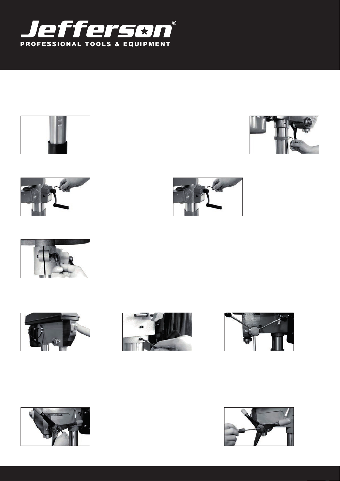
BASE & COLUMN
Select the base (Fig. 1) and align the column support over the large hole (Fig. 2).
Align the holes in the column support with those in the base and secure in place using the bolts and washers.
Using a spanner securely lighten all bots (Fig. 3).
We recommend mounting the base to stable surface for proper support. Slide the column into the column support (Fig.4).
Fig.1 Fig.2 Fig.3 Fig.4
Secure in place with 2 grub screws using the hex key (Fig. 5).
Fig.5
RACK & TABLE
2. Assemble the support and
rack onto the column, ensuring
the rack is positioned on the right
side of the column (when viewing
the product from the front)
(Fig. 7).
Fig.6 Fig.7
1. Install the rack into the table
support as shown (Fig. 6).
www.jeffersontools.com
User Manual
v.1.1
JEFPDB0350
6. ASSEMBLY
MAIN HOUSING
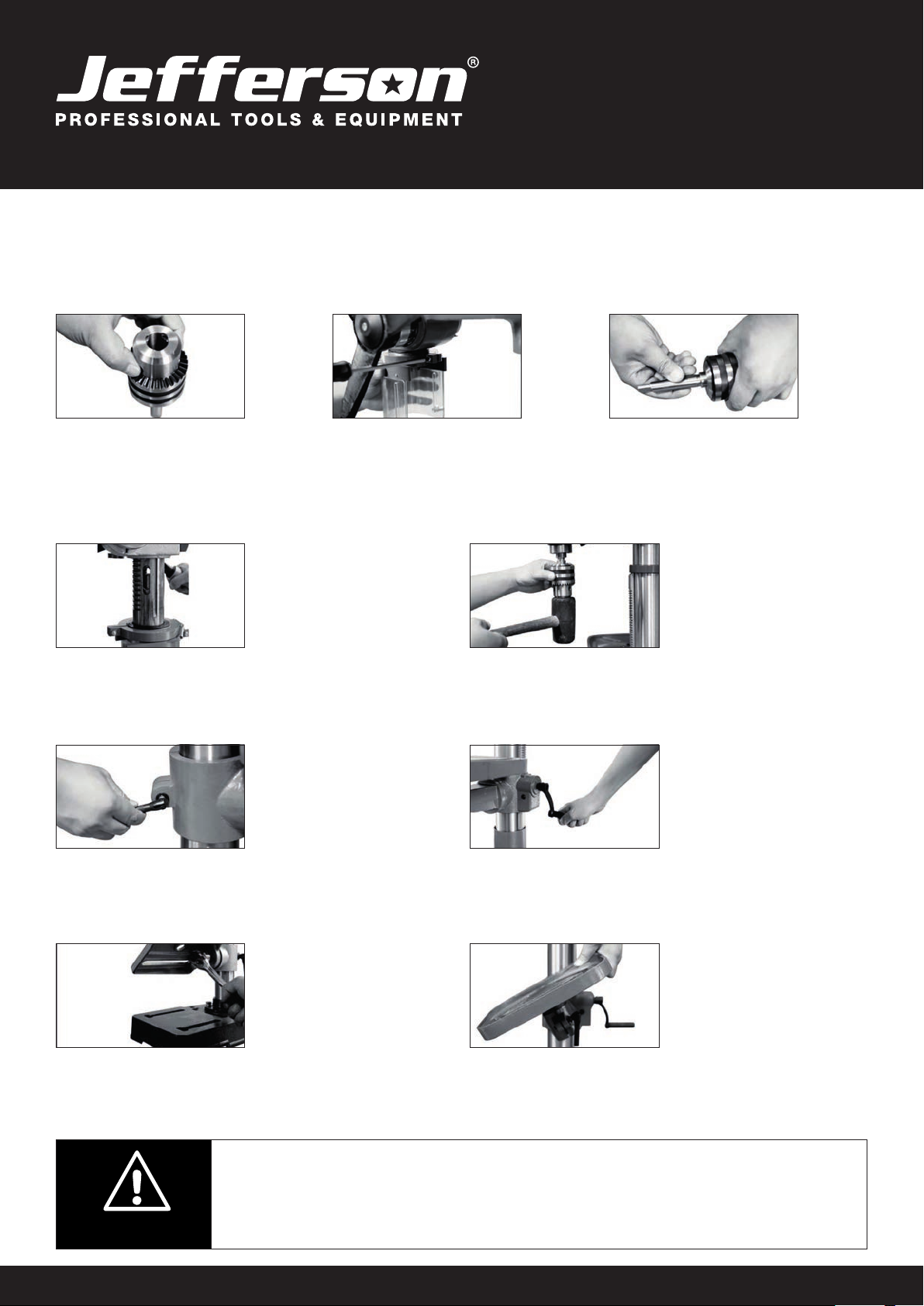
RACK & TABLE (Continued)
Fig.8 Fig.9
3. Slide the rack all the way down until it locates into the lower column
support(Fig. 8). Slide the collar, tapered side facing down, over the
column until it locates the rack.
Tighten the grub screw on upper collar (Fig.9).
Fig.10 Fig.10
4. Fix table adjustment handle on
the support (Fig. 10).
4. Fix table adjustment handle on
the support (Fig. 10).
Fig.10
5. Assemble table onto table
support, tighten in place with
table lock (Fig. 11).
1. Lift the main housing and slide
it down onto the column as far as
it will go (Fig. 12). Before securing
the housing, ensure the spindle
aligns with the table and base.
3. To t the feed wheel handles,
screw them into feed wheel hub
(Fig. 14).
2. To secure in position tighten
the grub screws on the left and
right hand sides of the housing
(Fig. 13).
4. For some cast iron feed
handle, lighten the 3 grub screws
to wheel hub (Fig.15) then x the
plastic case on cast iron feed
handle as shown Fig. 16.
Fig.12 Fig.13 Fig.14
Fig.15 Fig.16
www.jeffersontools.com
User Manual
v.1.1
JEFPDB0350
7. ASSEMBLY
CHUCK & ARBOR
Fig.17 Fig.18
1. Before any assembly, ensure the
chuck jaws are wound all the way up
(inside the chuck) to prevent them
from damage (Fig. 17).
Fig.19
Fig.20
3. Fit the tapered arbor end into the chuck by
hand, using reasonable fore (Fig. 19).
4. The arbor can then be
inserted into the quill,
twisting the arbor as you
insert, aligning the tang
into the slot. It should t
in with little resistance
(Fig. 20). Fig.21
5. Once it is located a rm tap
on the underside of the chuck
with a soft hammer is required
to secure it. The chuck & arbor
are installed correctly if they
cannot be pulley out with hand
force (Fig. 21).
2. Tighten Philip’s head screws
of the chuck guard to quill shaft
(Fig. 18).
TABLE HEIGHT & ADJUSTMENT
Fig.22
1. Loosen the table
support lock (Fig. 22).
Fig.23
2. Rotate the table
adjustment handle to set
the desired table height
and tighten the table rock
to secure the table in
position (Fig. 23).
TABLE BEVEL ADJUSTMENT
Fig.24
1. The bevel angel is
adjusted by loosening
the bolt that is located
underneath table support
with a spanner (Fig. 24).
Fig.25
2. After tilting the
working table (Fig. 25)
to appropriate position,
re-tighten the bolt to
secure its position.
When the table is angled/tilted,
ensure the workpiece is clamped
to the table.
CAUTION:

www.jeffersontools.com
User Manual
v.1.1
JEFPDB0350
8. ASSEMBLY
INSTALLING STRAIGHT SHANK DRILL BITS
Fig.26 Fig.27
1. Using the chuck key, loosen the
jaws of the chuck by rotating in an
anti-clockwise direction (Fig. 26).
Fig.28
3. Whilst holding the drill bit in one hand rotate
the top collar of the chuck in a clockwise
direction. Insert the chuck key into 1 of the
3 rotating holes and tighten until drill bit is
secure (Fig. 28).
2. Insert the drill bit into the chuck
(Fig.27)
MORSE TAPER DRILL BITS
Fig.29 Fig.30
To use Morse taper bits, remove
chuck and arbor.
1. Turn arbor until the tang aligns
with the slot in the quill (Fig. 29) .
Fig.31
3. Place tapper bit into the spindle hole,
twisting and pushing upward until bit is sung
(Fig. 31).
4. Place block of wood on the table and raise
up table until the tapered bit is.
2. 2. Insert the drill key into the
slot and tap rmly with a metal
hammer until it releases. (Ensure
the chuck jaws are wound all the
way up to prevent damage
(Fig. 30).
PRE-SETTING THE DRILLING DEPTH
BENCH TYPE
To set the depth of the hole, adjust the depth stop as follows:
1. Lower the chuck with the power OFF, until the drill bit touches the surface
of the workpiece, and hold in that position.
2. Spin down the adjuster nut so that the gap between its underside and top of bracket is the
depth of the hole required. Screw down the lock nut and lock it against the adjuster nut.
Fig.32
The drill is now set to drill holes to your pre-determined depth from that particular start point. i.e. Providing the surface of your workpiece is
at and level, you may drill a series of holes, each to the same depth. The scale and pointer can be used when drilling individual holes.
Lower the chuck until the drill bit touches the work, set the pointer against a point on the scale, and proceed to drill to the required depth,
using the scale.
www.jeffersontools.com
User Manual
v.1.1
JEFPDB0350
9. ASSEMBLY
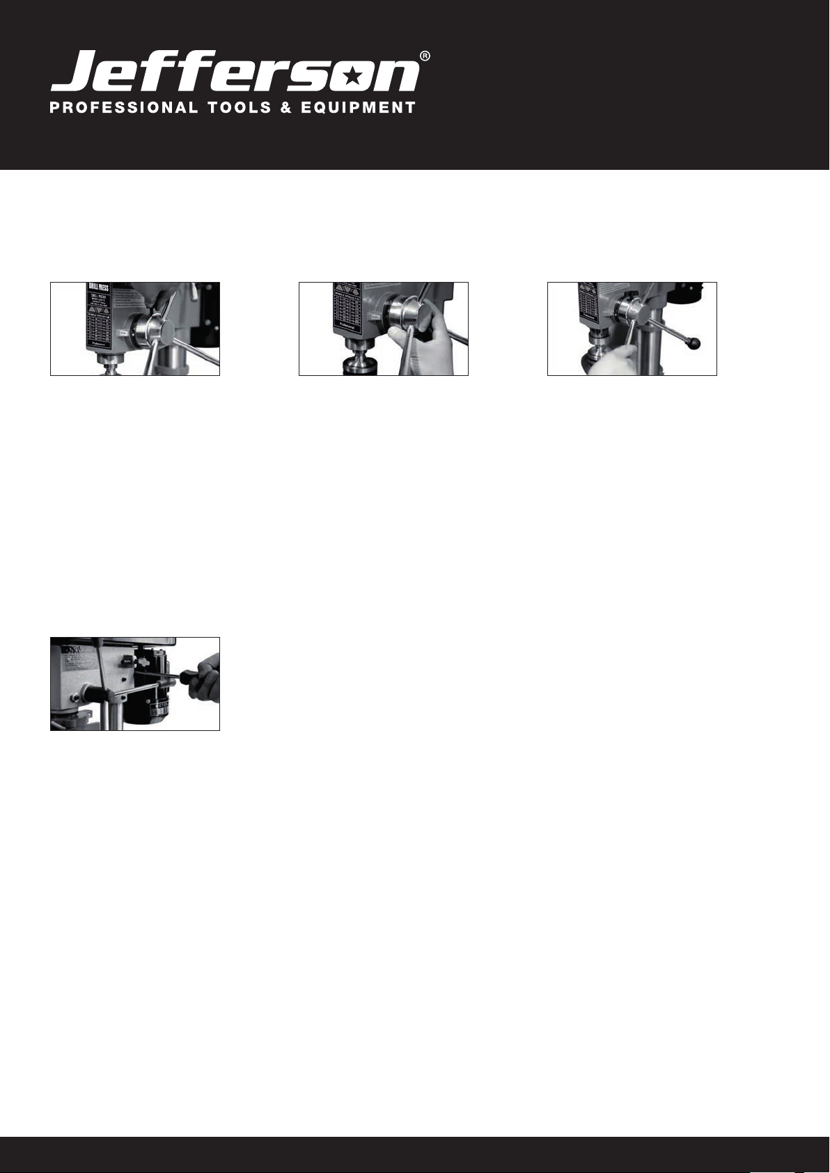
FLOOR TYPE
Fig.33 Fig.34
To stop spindle (and bit) at a desired depth:
1. Loosen depth stop lock knob by turning in an anti-clockwise direction (Fig. 33).
2. Rotate depth scale to the desired depth, then tighten half wing bolt (Fig. 34).
To hold the spindle (and bit) at a desired depth:
1. Loosen depth stop lock knob, turn feed wheel handle to lowest point (Fig.35).
2. Rotate depth scale to desired depth and re-tighten depth stop lock knob. This will hold assembly stationery at desired depth.
Fig.35
CHANGING THE SPEED
Fig.36
Before changing the speeds, ensure the machine is switched OFF, and disconnected from the power supply.
1. Open the pulley cover.
2. Slacken off the belt tension locking knob, to relieve any tension on the drive belt.
3. Consult the chart inside the pulley cover, and position the belt on the pulley’s according to the spindle speed required.
4. When the belt has been correctly positioned, re-tension by levering the motor away from the head. Lever the motor, with its bracket, away from
the head, so that tension is applied to the Fig.36 belt. Tension is correct when the belt deects by approx. ½”at its centre, when using
reasonable thumb pressure. Lock the motor in this position using the locking knob.

www.jeffersontools.com
User Manual
v.1.1
JEFPDB0350
10. OPERATION
TURNING ON AND OFF
Fig.42
Note: The pulley cover must be closed to operate the drill press.
1. Switch the drill press On by pressing the green(I)button on the switch (Fig.42-43).
2. Switch the drill press Off by pressing the red(O)button on the sw itch.
3. Secure your workpiece to the table if possible,use a vice or clamps.
DRILLING
1. Ensure the drill press is switched off and disconnected from the power supply.
2. Loosen the jaws of the chuck with the chuck key by turning in an anti-clockwise direction and
insert the selected drill bit into the as far as it will go.
3. Insert the chuck key into 1 of the 3 locating holes and tighten until drill bit is secure.
4. Select your drilling depth and secure the depth stop lock knob in position.
5. Adjust the table to your desired position.
6. Slowly rotate the feed wheel handles to bring the drill bit down towards the table and into your workpiece. After drilling a hole, release the feed
wheel handles slowly to return the chuck to its original position.
7. Continue the operation until the task is completed. When completed, switch the drill press Off by pressing the red (O) button on the switch.
Fig.43

www.jeffersontools.com
User Manual
v.1.1
JEFPDB0350
11. EXPLODED DIAGRAM OF BENCH PRESS

www.jeffersontools.com
User Manual
v.1.1
JEFPDB0350
11. PARTS LISTING FOR BENCH PRESS
1BASE 40 NUT
2COLUMN FLANGE 41 SPRING WASHER
3FLAT WASHER 42 MICRO SWITCH PRESSING CLAW
4SPRING WASHER 43 HEX. SOC SET SCREW
5OUTSIDE HEX. BOLT 44 MOTOR PULLEY
6OUTSIDE HEX. BOLT 45 CIRCLIP FOR HOLE
7SPRING WASHER 46 BEARING
8WORKING TABLE 47 KEYWAY SPINDLE
9TABLE SUPPORT 48 CIRCLIP FOR BEARING
10 ANGLE LABEL 49 SPINDLE PULLEY
11 LOCKING HANDLE 50 BELT
12 COLUMN 51 PLUG WITH CABLE
13 HANDLE TIP 52 NUT
14 HANDLE 53 SPRING COVER
15 GEAR SHAFT 54 SPRING
16 NUT 55 SCREW
17 A WORD HEAD SCREW 56 CIRCLIP FOR BEARING
18 HOUSING 57 CROSS RECESS HEAD TAPPING SCREW
19 HEX. SOC SET SCREW 58 SWITCH
20 WING KNOB 59 CALIBRATION LABEL
21 MOTOR SPRING 60 CROSS RECESSED PAN HEAD SCREW
22 MOTOR PUSH ROB 61 SWITCH BOX
23 WASHER 62 CROSS RECESSED PAN HEAD SCREW
24 MOTOR 63 GROUNDED PARTS
25 OUTSIDE HEX. BOLT 64 TOOTH LOCK WASHER
26 DAMPING WASHER 65 INDICATOR
27 CROSS RECESS PAN HD SCREW 66 NUT
28 FLAT WASHER 67 LIMITED BOLT
29 CROSS RECESS PAN HD SCREW 68 BEARING
30 FLAT WASHER 69 WASHER
31 PROTECTOR RING 70 SPINDLE SOCKET
32 CORD CLAMP 71 CIRCLIP FOR BEARING
33 NUT 72 CHUCK GUARD
34 CROSS RECESSED PAN HEAD SCREW 73 MAIN SPINDLE
35 PULLEY COVER ASSEMBLY 74 CHUCK
36 ROLL PIN 75 HEXAGON BAR WRENCH
37 PROTECTOR RING 76 HEXAGON BAR WRENCH
38 MICRO SWITCH 77 SPRING WASHER
39 FLAT WASHER

www.jeffersontools.com
User Manual
v.1.1
JEFPDB0350
TROUBLE SHOOTING
PROBLEM PROBABLE CAUSE REMEDY
Machine will not start. 1. Fuse
2. Other
1. Replace/ reset time delay fuse or circuit
breaker.
2. Return to an authorised service agent for
diagnosis.
Noisy operation (under load). a. Incorrect belt tension.
b. Dry spindle.
c. Loose pulley.
d. Loose belt.
e. Worn bearing.
a. Adjust tension.
b. Remove spindle and quill
assembly and lubricate.
c. Tighten pulley.
d. Adjust belt tension.
e. Replace bearing.
Bit burns or smokes. 1. Incorrect belt tension.
2. Swaft not coming out of hole.
3. Blunt bit.
4. Feeding too slow.
5. Not lubricated.
1. Change speed.
2. Retract bit frequency to clear swaft.
3. Sharpen or replace bit.
4. Feed fast enough to allow drill to cut.
5. Lubricate bit.
Excessive drill run-out or wobble. 1. Bent bit.
2. Worn spindle bearings.
3. Bit not properly installed in chuck.
4. Chuck not properly installed.
1. Use a straight bit.
2. Return to an authorised service agent.
3. Install bit centrally.
4. Ret chuck properly.
Drill binds for workpiece. 1. Workpiece pinching bit or
excessive feed pressure.
2. Improper belt tension.
1. Support or re-clamp workpiece.
2. Adjust tension.
For your safety always turn the main switch on the machine “off”
and remove the plug from the power supply before carrying out any
maintence or trouble shooting.
WARNING:

www.jeffersontools.com
User Manual
v.1.1
JEFPDB0350
EC Declaration of Conformity
We, Jefferson Professional Tools & Equipment, as the authorised European
Community representative of the manufacturer, declare that the following equipment
conforms to the requirements of the following Directives:
Directive: Description:
2014/30/EU (as amended) Electromagnetic compatibility
2006/42/EC (as amended) Machinery directive
2011/65/EC (as amended) Restriction of Hazardous Substance
Directive (RoHS)
Equipment Category: Bench Drill / Pillar Drill / Drill Press
Product Name/Model: JEFPDB0350
Notified Body: TÜV SÜD Product Service GmbH Zertifizierstellen
Ridlerstraße 65
80339 MÜNCHEN
Country : Germany
http://www.tuev-sued.de/ps
Notified Body Number: 0123
Signed by: Stephen McIntyre
Position in the company: Operations Director
Date: 31 January 2018
Name and address of manufacturer
or authorised representative:
Jefferson Tools, Herons Way, Chester Business Park,
Chester, United Kingdom, CH4 9QR
Telephone: +44 (0)1244 646 048
Fax: +44 (0)1244 241 191
Email: [email protected]

www.jeffersontools.com
User Manual
v.1.1
JEFPDB0350
Jefferson Professional Tools & Equipment, or hereafter “Jefferson” warrants its
customers that its products will be free of defects in workmanship or material. Jefferson
shall, upon suitable notication, correct any defects, by repair or replacement, of any
parts or components of this product that are determined by Jefferson to be faulty
or defective. This warranty is void if the equipment has been subjected to improper
installation, storage, alteration, abnormal operations, improper care, service or repair.
Warranty Period
Jefferson will assume both the parts and labour expense of correcting defects during
the stated warranty periods below.
All warranty periods start from the date of purchase from an authorised Jefferson dealer.
If proof of purchase is unavailable from the end user, then the date of purchase will be
deemed
to be 3 months after the initial sale to the distributor.
1 Year
• Jefferson 350W Bench Drill [JEFPDB0350].
90 Days
• All replacement parts purchased outside of the warranty period
Important: All parts used in the repair or replacement of warranty covered equipment
will be subject to a minimum of 90 days cover or the remaining duration of the warranty
period from the original date of purchase.
Warranty Registration / Activation
You can register and activate your warranty by visiting the Jefferson Tools website using
the following address: www.jeffersontools.com/warranty and completing the online
form.
Online warranty registration is recommended as it eliminates the need to provide proof
of purchase should a warranty claim be necessary.
Warranty Repair
Should Jefferson confirm the existence of any defect covered by this warranty the
defect will be corrected by repair or replacement at an authorized Jefferson dealer or
repair centre.
Packaging & Freight Costs
The customer is responsible for the packaging of the equipment and making it ready
for collection. Jefferson will arrange collection and transportation of any equipment
returned under warranty. Upon inspection of the equipment, if no defect can be found
or the equipment is not covered under the terms of the Jefferson warranty, the customer
will be liable for any labour and return transportation costs incurred. These costs will be
agreed with the customer before the machine is returned.
NOTE: * Jefferson reserve the right to void any warranty for damages identified as being
caused through misuse *
Warranty Limitations
Jefferson will not accept responsibility or liability for repairs made by unauthorised
technicians or engineers. Jefferson’s liability under this warranty will not exceed the
cost of correcting the defect of the Jefferson products.
Jefferson will not be liable for incidental or consequential damages (such as loss of
business or hire of substitute equipment etc.) caused by the defect or the time involved
to correct the defect. This written warranty is the only express warranty provided by
Jefferson with respect to its products.
Any warranties of merchantability are limited to the duration of this limited warranty for
the equipment involved.
Claiming Warranty Coverage
The end user must contact Jefferson Professional Tools & Equipment:
(Tel: +44 (0) 1244 646 048) or their nearest authorised Jefferson dealer where final
determination of the warranty coverage can be ascertained.
Step 1 - Reporting the Defect
Online Method:
Visit our website www.jeffersontools.com/warranty and complete the Warranty Returns
form. You can complete the form online and submit it to us directly or download the
form to print out and return by post.
Telephone Method:
Contact your Jefferson dealer or sales representative with the following information:
• Model number
• Serial number (usually located on the specification plate)
• Date of purchase
A Warranty Returns form will be sent to you for completion and return by post or fax,
together with details of your nearest authorised Jefferson repair centre. On receipt
of this form Jefferson will arrange to collect the equipment from you at the earliest
convenience.
Step 2 - Returning the Equipment
It is the customer’s responsibility to ensure that the equipment is appropriately and
securely packaged for collection, together with a copy of the original proof of purchase.
Please note that Jefferson cannot assume any responsibility for any damage incurred
to equipment during transit. Any claims against a third party courier will be dealt with
under the terms & conditions of their road haulage association directives.
NOTE: Jefferson will be unable to collect or process any warranty requests without a
copy of the original proof of purchase.
Step 3 - Assessment and Repair
On receipt, the equipment will be assessed by an authorised Jefferson engineer and it
will be determined if the equipment is defective and in need of repair and any repairs
needed are covered by the warranty policy. In order to qualify for warranty cover all
equipment presented must have been used, serviced and maintained as instructed in
the user manual.
Where repair is not covered by the warranty a quotation for repair, labour costs and
return delivery will be sent to the customer (normally within 7 working days). Note: If the
repair quotation is not accepted Jefferson Professional Tools & Equipment will invoice 1
hour labour time at £30 per hour plus return carriage costs (plus VAT).
In cases where no fault can be found with the equipment, or, if incorrect operation of the
equipment is identified as the cause of the problem, a minimum of 1 hour labour at £30
per hour plus carriage costs will be required before the equipment will be despatched
back to the customer.
Any equipment repaired or replaced under warranty will normally be ready for shipment
back to the customer within 7 working days upon receipt of the equipment at an
authorised Jefferson Repair centre (subject to part availability). Where parts are not
immediately available Jefferson will contact you with a revised date for completion of
the repair.
General Warranty Enquiries
For any further information relating to Jefferson warranty cover please call:
Disclaimer:
The information in this document is to the best of our knowledge true and accurate, but
all recommendations or suggestions are made without guarantee. Since the conditions
of use are beyond their control, Jefferson Tools® disclaim any liability for loss or
damage suffered from the use of this data or suggestions. Furthermore, no liability is
accepted if use of any product in accordance with this data or suggestions infringes any
patent. Jefferson Tools® reserve the right to change product specifications and warranty
statements without further notification. All images are for illustration purposes only.
LIMITED WARRANTY STATEMENT

www.jeffersontools.com
User Manual
v.1.1
JEFPDB0350
NOTES

www.jeffersontools.com
User Manual
v.1.1
JEFPDB0350
JEFPDB0350
350W
BENCH
DRILL
Table of contents
Other Jefferson Drill manuals

Jefferson
Jefferson JEFMGNDR40-110 User manual

Jefferson
Jefferson JEFMAGDPER35-230 User manual

Jefferson
Jefferson JEFPDB1500 User manual

Jefferson
Jefferson JEFPDB1100 User manual

Jefferson
Jefferson JEFPDB0550 User manual

Jefferson
Jefferson JEFMAGD42HD/110 User manual

Jefferson
Jefferson JEFMAGDAUT35-230 User manual


