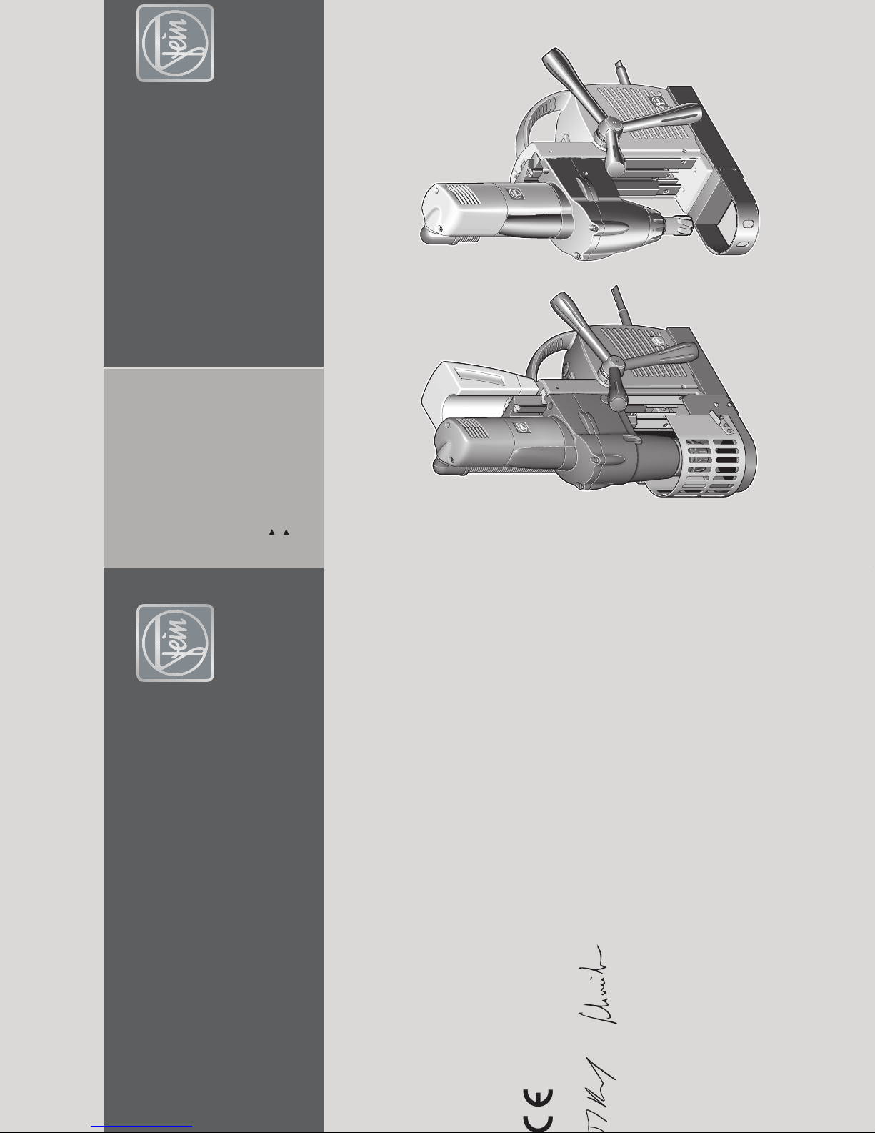
Fein KBM 52 U User manual

C. & E. FEIN GmbH. Printed in Germany. Abbildungen unverbindlich. Technische Änderungen vorbehalten. 3 41 01 063 06 0 BY 2006.06Z DE.
EN 61029, EN 55014, EN 61000-3-2, EN 61000-3-3
98/37/EG, 89/336/EWG
Hammersdorf
Quality Manager Dr. Schreiber
Manager of R&D department
FEIN Service
C. & E. FEIN GmbH
Hans-Fein-Straße 81
D-73529 Schwäbisch Gmünd-Bargau
Telefon +49 (0) 7173 183-465
Telefax +49 (0) 7173 183-844
www.fein.com
KBM52U 7 270 31
KBM50QX 7 270 33

2
Deutsch ____________ Gebrauchsanleitung________________
English _____________ Instruction manual ________________
Français ____________ Notice d'utilisation ________________
Italiano _____________ Libretto delle Istruzioni per l’uso_______
Nederlands __________ Gebruiksaanwijzing ________________
Español_____________ Instrucciones de uso _______________
Português ___________ Instrução de serviço _______________
EÏÏËÓÈο ____________ √‰ËÁ›Â˜ ¯ÂÈÚÈÛÌÔ‡ _________________
Dansk ______________ Brugsanvisning ___________________
Norsk ______________ Bruksanvisning ___________________
Svenska ____________ Bruksanvisning ___________________
Suomi ______________ Käyttöohje ______________________
Magyar _____________ Használati útmutató _______________
âesky______________ Návod k pouÏití___________________
Slovensky ___________ Návod na pouÏívanie _______________
Polski______________ Instrukcja obslugi _________________
На русском языке ___ Руководство по эксплуатации __
""
"" _____________ ##
##$$
$$%&'%&'
%&'%&'
____________________
6
14
22
30
38
46
54
62
70
78
86
94
102
110
118
126
134
142
3 41 01 063 06 0.book Seite 2 Donnerstag, 12. Mai 2005 8:42 08

3
4
2
3
6 5
1
6
a
3 41 01 063 06 0.book Seite 3 Donnerstag, 12. Mai 2005 8:42 08

4
12
8
KBM 52 U
KBM 52 U
KBM 50 Q
7
9
9
13
10
11
3 41 01 063 06 0.book Seite 4 Donnerstag, 12. Mai 2005 8:42 08

5
j
l
m
c
e
f
g
i
h
18
15
b
16
KBM 52 U
KBM 52 U
14 17
d
k
j
3 41 01 063 06 0.book Seite 5 Donnerstag, 12. Mai 2005 8:42 08

14
KBM 52 U / KBM 50 Q
EN
Instruction manual for core drill.
Symbols, abbreviations and terms
used.
The symbols used in this Instruction Manual and
where necessary on the power tool, serve to
draw your attention to possible hazards when
working with this power tool.
It is mandatory for you to understand the sym-
bols/information and to act accordingly, in order
for the power tool to be implemented more
efficiently and more safely.
The safety warnings, information and symbols
do not serve as a substitute for the measures to
be taken according to the regulations for the
prevention of accidents.
Symbol Term, meaning Explanation
➤Action Action to be taken by the user
General prohibition sign Follow the instructions in the adjacent text!
Touching prohibited Do not touch the rotating parts of the power tool.
Secure against falling Secure the power tool with the clamping strap if
there is danger of it falling.
General mandatory sign Follow the instructions in the adjacent text!
Read documentation Be absolutely sure to read the enclosed documen-
tation such as the Instruction Manual and the Gen-
eral Safety Instructions.
Open the folding page For a better understanding, unflap the folding page
at the beginning of this Instruction Manual.
Pull out mains plug Before commencing this working step, pull the
mains plug out of the socket. Otherwise there will
be danger of injury if the power tool should start
unintentionally.
Use eye-protection Use eye-protection during operation.
Wear ear protection Use ear protection during operation.
Use dust mask Use a dust mask during operation.
Use protective gloves Use protective gloves during operation.
Danger warning Observe the information in the adjacent text!
Hot surface warning An exposed surface is very hot if touched and
therefore dangerous.
European conformity symbol Confirms the conformity of the power tool with
the directives of the European Community.
3 41 01 063 06 0.book Seite 14 Donnerstag, 12. Mai 2005 8:42 08

KBM 52 U / KBM 50 Q
15
EN
For your safety.
Do not use this power tool before you
have thoroughly read and completely
understood this Instruction Manual and the
enclosed “General Safety Instructions” (docu-
ment number 3 41 30 054 06 1), including the
figures, specifications, safety regulations and the
signs indicating DANGER, WARNING and
CAUTION.
Please also observe the relevant national
industrial safety regulations
(e.g. in Germany: BGV A2).
Non-observance of the safety instructions in the
said documentation can lead to an electric shock,
burns and/or severe injuries.
This Instruction Manual and the enclosed “Gen-
eral Safety Instructions” should be kept for later
use and enclosed with the power tool, should it
be passed on or sold.
DANGER This sign warns of a directly imminent, dangerous
situation. A false reaction can cause a severe or
fatal injury.
WARNING This sign indicates a possible dangerous situation
that could cause severe or fatal injury.
CAUTION This sign warns of a possible dangerous situation
that could cause injury.
It is forbidden to dispose of
the product in the unsorted
household waste.
Worn out power tools and other electrotechnical
and electrical products should be sorted sepa-
rately for environment-friendly recycling.
Class of protection I Product with basic insulation and additional con-
nection to the earth conductor of all touchable
and conductive parts.
mm Millimeter Unit of measure for length, width, height or depth
kg Kilogram Unit of measure for the mass
V Volt Unit of measure for the electric voltage
A Ampere Unit of measure for the electric current intensity
W Watt Unit of measure for the output
N Newton Unit of measure for the force
min Minutes Unit of measure for the time
~ or a. c. Current type Alternating current
or d. c. Current type Direct current
1 ~ Power supply type Alternating current single-phase
noNo-load speed Revolution speed at no-load
1/min per minute Unit of measure for number of revolutions,
strokes, impacts or oscillations per minute
ØDiameter Diameter of a round part
Symbol Term, meaning Explanation
3 41 01 063 06 0.book Seite 15 Donnerstag, 12. Mai 2005 8:42 08

16
KBM 52 U / KBM 50 Q
EN
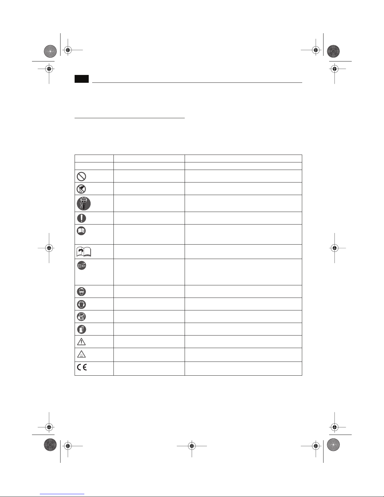
Special safety instructions.
Secure the power tool with the clamping strap
supplied if there is danger of it falling, especially
for work carried out at a height, on vertical con-
struction elements or above the head. If there is a
power cut, or the mains plug is pulled out, the
magnetic holding power is not maintained.
If work is carried out on vertical construction ele-
ments or above the head, prevent any fluid (cool-
ant) from penetrating the power tool. There is
danger of an electric shock. Work here using a
coolant spray.
Avoid touching the drilled core that is automati-
cally ejected by the centering pin when the work-
ing procedure is finished. Contact with the core
when it is hot, or if it falls, can cause personal
injuries.
Operate the power tool only from earthing contact
sockets that comply with the specifications. Do
not use any connection cables that are damaged;
use extension cables with an earthing contact that
are checked at regular intervals. A earth conduc-
tor without continuity can cause an electric
shock.
Do not rivet or screw any name-plates or signs
onto the power tool. If the insulation is damaged,
protection against an electric shock will be inef-
fective. Adhesive labels are recommended.
Wear personal protective equipment. Depending
on the application, use a face shield, safety gog-
gles or safety glasses. Wear ear protection. The
safety glasses must be capable of protecting
against flying particles generated by the various
different operations. Prolonged exposure to
high intensity noise may cause loss of hearing.
Do not use accessories which are not specifically
designed and recommended by the power tool
manufacturer. Safe operation is not ensured
merely because an accessory fits your power
tool.
Clean the ventilation openings on the power tool at
regular intervals. The motor blower draws dust
into the housing. An excessive accumulation of
metallic dust can cause an electrical hazard.
The guard protecting against chippings and acci-
dental contact must always be mounted during
operation. Hot, sharp chippings can cause per-
sonal injuries.
At a glance.
The following numbering used for the
operating elements relates to the figures
at the beginning of this Instruction Manual.
1 Coolant container
For storing coolant.
2 Capstan handle
For moving the drill motor up and down.
3 Depth scale
1 segment represents an upward or down-
ward movement of the drill motor of 1 mm.
4 Magnetic foot
For fastening the core drill to a magnetizable
base.
5 Slit for the clamping strap
Secure the core drill using the clamping
strap.
6 Guard protecting against chippings and acci-
dental contact
For preventing accidental contact with the
rotating parts.
Hook for locking (6a).
7 Gear switch
For setting the gear level to slow or fast
speed.
8 Fixation screw for coolant container
For fastening the coolant container.
9 Motor switch
For starting and stopping the motor.
10 “Slow” button
For reducing the speed.
11 Main switch
For switching the magnet ON and OFF.
12 Coolant stopcock
For setting the quantity of coolant.
13 Lever for setting the stroke range
For setting the variable stroke range of the
motor.
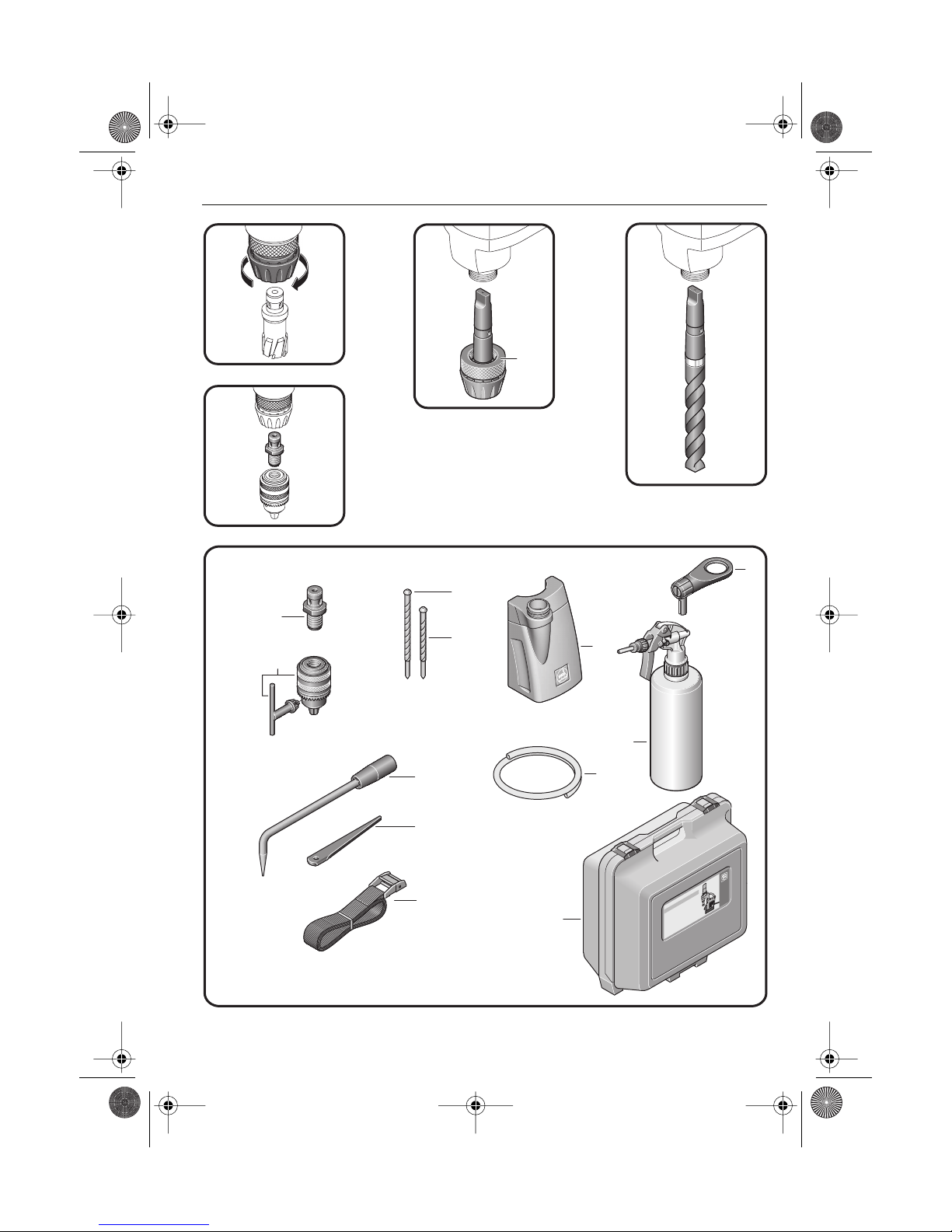
14 Tool holder (Quick IN)
For clamping the tool.
3 41 01 063 06 0.book Seite 16 Donnerstag, 12. Mai 2005 8:42 08

KBM 52 U / KBM 50 Q
17
EN
15 Adapter for geared drill chuck with core drill
thread (M 18x6/P 1.5)
For clamping the twist drill and core drill
bits.
16 Adapter with securing nut (16b)
Adapter for Quick IN tool holder.
17 Use of spiral bits MK 3
18 Standard accessories
Adapter (M 18x6/P 1.5) (18c),
Geared drill chuck with drill-chuck
wrench (18d),
Long centering pin (119 mm) (18e),
Short centering pin (104 mm) (18f),
Chip hook (18g),
Drift (18h),
Clamping strap (18i),
Coolant container (18j),
Pump holder (18k),
Coolant tube (18l),
Power tool carry case, plastic (18m).
Only part of the accessories described or shown
in this instruction manual will be included with
your power tool.
For all the parts applicable for your power tool,
please see the spare parts list.
Intended use of the power tool.
This power tool is intended for commercial use
as a core drill for drilling materials with a mag-
netizable surface using core drill bits or twist
drill bits, and for reaming, countersinking and
tapping in a weather-protected environment
using the application tools and accessories rec-
ommended by FEIN.
The power tool can be used horizontally, verti-
cally or overhead.
Instructions for putting into
operation.
Please make sure that the contacting surface for
the magnetic foot is level, clean and rust-free.
Remove any varnish or primer.
When working on materials that are not mag-
netizable, suitable fixation devices, obtainable as
accessories from FEIN, e. g. suction plate, vac-
uum plate or pipe-drilling device must be used.
When work on steel materials with a material
thickness of less than 12 mm, the workpiece
must be reinforced with an additional steel plate
in order to guarantee the magnetic holding
power.
Mounting the guard protecting against
chippings and accidental contact (Figure 6).
The guard protecting against chippings and
accidental contact must always be mounted
during operation.
➤Mount the guard protecting against chip-
pings and accidental contact (6).
➤To remove any accumulated chippings,
open the guard protecting against chip-
pings and accidental contact (6).
➤Before commencing operation, fasten
the guard protecting against chippings and
accidental contact (6) with the hook (6a).
Mounting the coolant container
(Figures 1 + 8 + 12).
➤Place the filled coolant container (1) into
the holder provided on the motor housing.
Only use cooling lubricant that is capable of
being pumped.
➤Fasten the coolant container (1) using
the fixation screw (8).
➤Connect the coolant tube (18l).
3 41 01 063 06 0.book Seite 17 Donnerstag, 12. Mai 2005 8:42 08

18
KBM 52 U / KBM 50 Q
EN
Operating instructions.
Adjustments.
Set the stroke range (Figure 13).
For changing the tool easily and fast, the setting
of the stroke range is infinitely variable.
➤Loosen the lever (13) and set to the
required stroke range.
➤Before commencing operation, tighten
the lever (13) firmly again.
Changing the tool.
Core bit (Figure 14).
➤Push the centering pin (18e) through the
core bit.
➤Turn the Quick IN clamping collar (14)
of the tool holder anti-clockwise and insert
the core bit with the centering pin.
➤Let go of the Quick IN clamping col-
lar (14) and turn the core bit in the tool
holder until the catch notches.
Twist drill and core drill bits with M 18x6/P 1.5
(Figure 15).
➤Screw the adapter (15) onto the geared
drill chuck.
➤Turn the Quick IN clamping collar (14)
of the tool holder anti-clockwise and insert
the adapter (15) in the same way as the
core bit.
The adapter can also be used for suitable core
bits.
Twist drill bit with morse taper arbor
(KBM 52 U, Figures 16 + 17).
➤Loosen the securing nut (16b) of the
tool holder. The securing nut has a left-
handed thread.
➤Knock the adapter (16) out using the
drift (18h).
➤Clean the inner taper of the drift shaft
and insert the MK 3 spiral bit (17).
General operating instructions.
Selecting the gear level (Figure 7).
Set the gear level to setting “I” for operations
requiring a low speed and a high torque. This
setting is suitable for drilling with large drilling
diameters (26 mm–50 mm) and for tapping.
Set the gear level to setting “II” for operations
requiring a high speed and a low torque. This
setting is suitable for drilling with small drilling
diameters (12 mm–26 mm).
Only switch over the gear level when the motor
is at a standstill.
Putting into operation.
First check that the mains supply lead and
mains plug are not damaged.
Secure the power tool with the clamping
strap (18i) if there is danger of it falling.
KBM 52 U: Note: If permissible, open the coolant
stopcock (12).
➤Switch on the main (magnet) switch (11)
for the magnet to clamp and hold the core
drill.
Starting and stopping the motor (KBM 52 U):
Starting the motor in clockwise rotation, full
speed:
➤Briefly tap the “R” on the motor
switch (9) (clockwise rotation).
Stopping the motor during clockwise rotation:
➤Briefly tap “L/OFF” on the motor
switch (9).
Starting the motor in anti-clockwise rotation:
➤Continuously press “L/OFF” (anti-clock-
wise rotation) on the motor switch (9).
Stopping the motor during anti-clockwise rota-
tion:
➤Let go of the motor switch (9).
Starting and stopping the motor (KBM 50 Q):
Starting:
➤Switch on the motor switch (9).
Stopping:
➤Switch off the motor switch (9).
3 41 01 063 06 0.book Seite 18 Donnerstag, 12. Mai 2005 8:42 08

KBM 52 U / KBM 50 Q
19
EN
Reducing the speed (KBM 52 U, Figure 10):
Changing the speed is only effective for clock-
wise rotation. In anti-clockwise rotation the
motor runs at a constant reduced speed.
➤Start the motor in clockwise rotation.
Reducing the speed:
➤Press the “slow” button (10).
For maintaining the speed:
➤Let go of the “slow” button (10).
For further reducing the speed:
➤Press the “slow” button (10) once again.
Storing the set speed value:
The value of the speed last set is automatically
stored.
Starting with the stored speed value:
➤Press the “slow” button (10) and briefly
tap the “R” (clockwise rotation) on the
motor switch (9).
Putting out of operation:
➤Switch the magnet off by pressing the
main switch (11).
Instructions:
– The magnetic foot (4) is monitored by a cur-
rent sensor. If the magnetic foot is defective
the motor will not start.
– The motor automatically switches off in the
case of overload. It can be restarted with
motor switch (9).
– If the current supply is interrupted while the
motor is running, a protection circuit prevents
the motor from restarting automatically. The
motor has to be restarted with motor
switch (9).
Working instructions for core drilling.
➤Punch-mark the drilling place marked.
➤Position the drill bit with the centering
pin (18e) on the punch-mark.
➤Carefully start boring until a circular cut
is formed.
Do not stop the drill motor during the
drilling procedure.
Only remove the core bit from of the drill-
ing hole while the motor is running.
➤If the core bit should remain stuck in the
material, stop the drill motor and carefully
turn the core bit out anti-clockwise.
Remove the chippings and the bored core
after each drilling process.
Do not touch the chippings with your bare
hand. Always use a chip hook.
Do not damage the cutters when changing
the bit.
➤When core drilling layered material,
remove the core and the chippings after
drilling each layer.
Repair and customer service.
Regular cleaning.
Carry out the following steps once a week, or
more often if used frequently:
➤Clean the cooling air vents.
Use non-metallic tools to clean the air vents.
➤Blow out the interior of the power tool
from outside through the air vents with
dry, compressed air.
If required, you can change the following parts
yourself:
– Application tools
– Coolant container (18j)
– Coolant tube (18l)
For repairs, we recommend our FEIN customer
service centre, the FEIN authorised service cen-
tres and FEIN agencies. For addresses, see the
enclosed “General Safety Instructions”.
When carrying out your own repairs by quali-
fied electricians we supply the repair documen-
tation upon request.
Repairs may only be carried out by quali-
fied electricians in conformity with the
valid regulations.
Please always hand this Instruction Manual
to the those carrying out the repair.
3 41 01 063 06 0.book Seite 19 Donnerstag, 12. Mai 2005 8:42 08

20
KBM 52 U / KBM 50 Q
EN
If the supply cord of this power tool is
damaged it must be replaced by a specially
prepared cord available through the FEIN cus-
tomer service centre.
Accessories.
Only use accessories recommended by FEIN.
Warranty and liability.
The warranty for the product is valid in accord-
ance with the legal regulations in the country
where it is marketed.
In addition, FEIN also provides a guarantee in
accordance with the FEIN manufacturer’s guar-
antee. For further details on this, please contact
your specialist dealer, your national FEIN repre-
sentative, or the FEIN customer service centre.
Declaration of conformity.
FEIN declares itself solely responsible for this
product conforming with the documents and
standards given on the last page of this Instruc-
tion Manual.
Environmental protection, disposal.
Packaging, worn out power tools and accesso-
ries should be sorted for environment-friendly
recycling. Further information can be obtained
from your specialist dealer.
3 41 01 063 06 0.book Seite 20 Donnerstag, 12. Mai 2005 8:42 08

KBM 52 U / KBM 50 Q
21
EN
Specifications.
Emission values for sound and vibration
(Two-figure – specifications as per ISO 4871)
Type KBM 52 U KBM 50 Q
Reference number 7 270 31 7 270 30
Power input 1200 W 1200 W
Output 640 W 680 W
Speed, full load
Clockwise
1st gear 130 –260 rpm 260 rpm
2nd gear 260 –520 rpm 520 rpm
Anti-clockwise
1st gear 160 rpm –
2nd gear 320 rpm –
Power supply type 1 ~ 1 ~
Weight 13.7 kg 12.0 kg
Class of protection I I
Drilling-Ø Steel max.
Core bit 50 mm 50 mm
Spiral bit 23 mm 16 mm
Tap M 16 M 16
Magnetic holding power 11 000 N 11 000 N
Max drilling depth with core bits 50 mm 50 mm
Height of drill jig 368 mm 368 mm
Stroke 135 mm 135 mm
Total stroke range 310 mm 310 mm
Magnetic foot plate dimensions 180 x 90 mm 180 x 90 mm
Sound emission
Measured A-weighted sound power level LwA
(re 1 pW), in decibels 96 96
Measuring inaccuracy KwA, in decibels 3 3
A-weighted emission pressure power level measured
at the workplace LpA (re 20 µPa), in decibels 83 83
Measuring inaccuracy KpA, in decibels 3 3
Vibration emission
Rated acceleration, in m/s20.6 0.6
Inaccuracy K, in m/s21.5 1.5
REMARK: The sum of the measured emission value and respective measuring inaccuracy represents
the upper limit of the values that can occur during measuring.
Wear ear protection!
For measurement values obtained according to the respective product standard, see the last page of
this Instruction Manual.
3 41 01 063 06 0.book Seite 21 Donnerstag, 12. Mai 2005 8:42 08
Other manuals for KBM 52 U
2
This manual suits for next models
1
Table of contents
Other Fein Drill manuals

Fein
Fein HandyMaster ABS 9V User manual

Fein
Fein DSk658-1 User manual

Fein
Fein ABOP6 User manual

Fein
Fein HandyMaster ASB 14V User manual

Fein
Fein MBS 16 User manual

Fein
Fein ASKEU 636 Kin User manual

Fein
Fein Handy Master ABS9 User manual

Fein
Fein KBM 65 U User manual

Fein
Fein kbb38x Setup guide

Fein
Fein ASge636 User manual

Fein
Fein ABS18 Q User manual

Fein
Fein DSk 672 User manual

Fein
Fein Tapper ASge 636 User manual

Fein
Fein ABS 14 Setup guide

Fein
Fein Slugger JHM Magforce X User manual

Fein
Fein BOP6 User manual

Fein
Fein KBU 35 Q User manual

Fein
Fein KBH25 User manual

Fein
Fein KBM 52 U User manual

Fein
Fein DDSk 111 User manual