Jegs 81426 User manual

Installation Instructions for 81426
Hydraulic Lift Cart
500 lb. Capacity
Specifications
Capacity
500 lb.
Lift Range
9-1/4” to 28-1/2”
Table Size
27-3/4” x 17-3/4”
Important Safety Information
Assembly Precautions
1. Wear ANSI-approved safety goggles and heavy-duty gloves during assembly and use.
2. Keep assembly area clean and well lit.
3. Assemble only according to these instructions. Improper assembly can create hazards.
4. Keep bystanders out of the area during assembly.
5. Do not assemble when tired or when under the influence of drugs or medication.
Use Precautions
1. Do not exceed 500 lb. max weight capacity. Be aware of dynamic loading! Sudden load movement may briefly create
excess load causing product failure.
2. Use only on flat, level and hard surface capable of supporting the Lift Table and any item(s) placed on table. Evenly
distribute load on table to avoid tipping.
3. Use as intended only. Do not use Lift Table to lift or transport people.
4. Follow all hydraulic bleeding instructions specified in this manual.
5. This product is not a toy. Do not allow children to play with or near this item.
6. Use as intended only.
7. Do not adjust Safety Valve.
8. Keep clear of load while lifting and lowering.
9. Lower load slowly.
10. Do not use for aircraft purposes.
11. Inspect before every use; do not use if parts are loose or damaged.
12. Maintain product labels and nameplates. These carry important safety information.
Assembly Instructions
Read the entire IMPORTANT SAFETY INFORMATION section at the
beginning of this document including all text subheadings therein
before setup or use of this product.
1. With assistance, grip the Base (9) of the Hydraulic Lift Table and
lift it from the box. Do not just grip the Table. Doing so will leave the
unit's frame in the packaging. Wheels (12)
2. Alternative: set the packaging sideways, grip the Base, and slide Lock Nuts (11)
the Lift Table out of the box
Washers (29)
3. Turn the Lift Table on its side.
Bushings (13)
Bolts (14)
Figure A
1-800-345-4545 jegs.com

4. Slide Bushing through center hole in front Wheel (12).
5. Set Wheel in the Wheel frame of the Base (9).
6. Slide the Bolt (14) through the Washer (29), Wheel Frame,
and Bushing (13).
Wrench
7. Use a wrench (sold separately) to fasten Lock Nut onto Bolt,
until the Front Wheel is secured in place.
8. Repeat steps 3-7 for other front Wheel.
9. Slide Pump Lever (23) into Connecting Rod (22), aligning the Washer
installation holes.
10. Slide the Bolt (35) through the Washer (15) and through the
installation holes. Wheel Frame
11. Use the wrench to fasten the Lock Nut over the Bolt, securing
Pump Lever (23) in place. See Figure C.
12. Slide the ends of the Handle (31) into the handle slots on the Base.
13. Use the wrench to tighten the Bolts (20) until the Handle is Front Wheel
fastened in place. See Figure D.
14. Test the Lift Table to make sure it functions properly
before using it to lift a load. Lock Nut
Figure B
Connecting Rod (22)
Handle (31)
Bolt (35)
Wrench
Pump Lever
Wrench (23)
Figure C
Bolt (20)
Base (9)
Figure D
1-800-345-4545 jegs.com
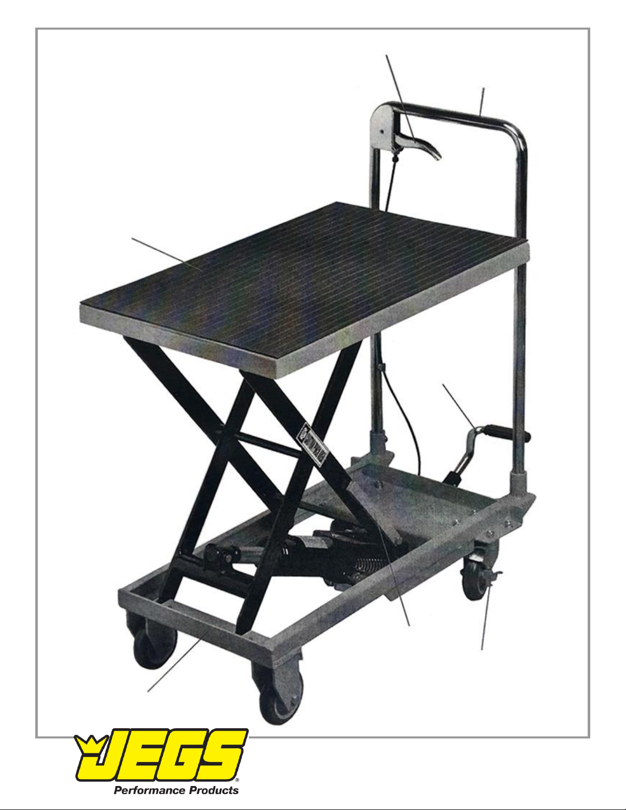
Operating Diagram Control Lever
Handle
Lift Table
Pump Lever
Safety Bar
Locking Caster
Base
1-800-345-4545 jegs.com
Operating Instructions
Read the ENTIRE IMPORTANT SAFETY INFORMATION section at the beginning of this manual including all
text under subheadings therein before set up or use of this product.
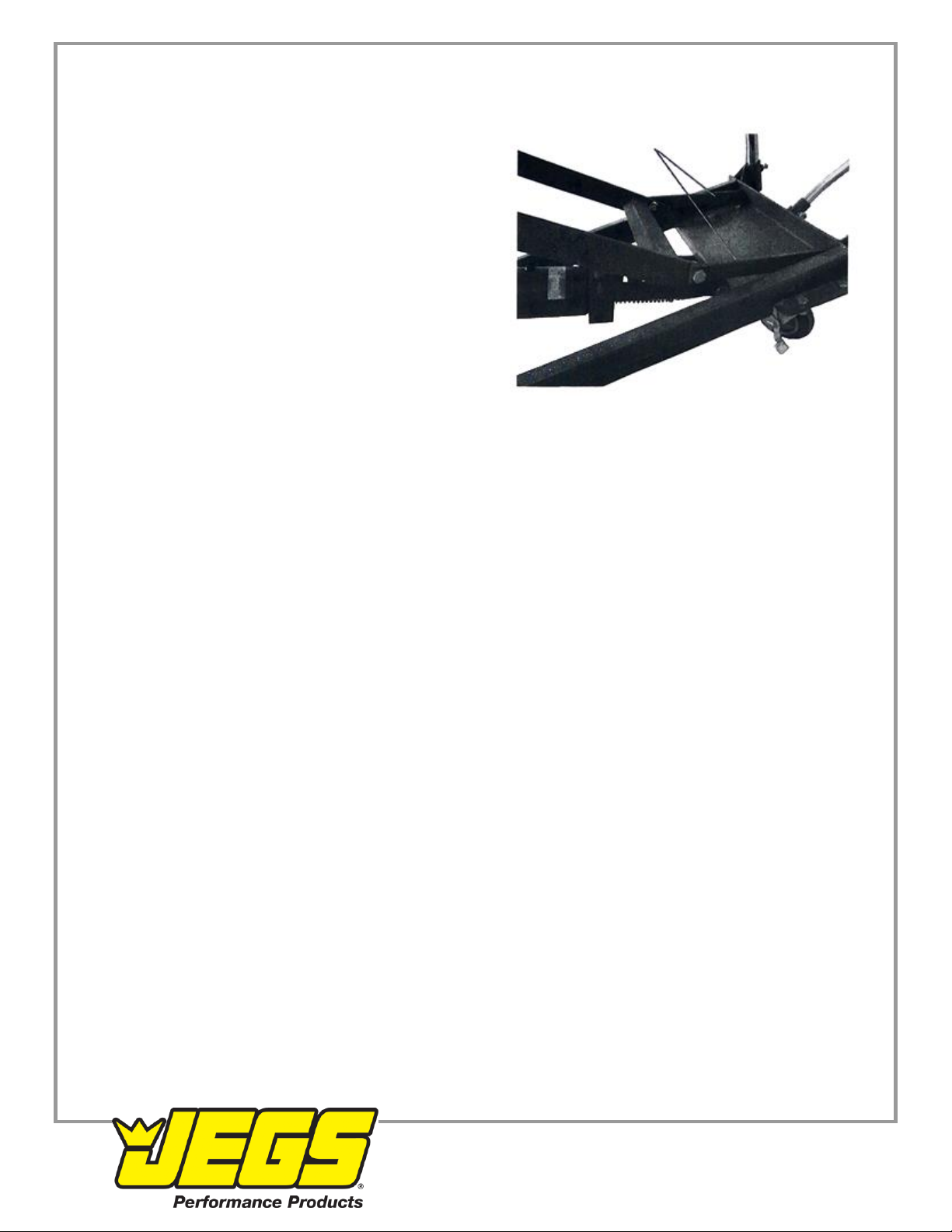
1. Lock the back Casters to prevent the Lift Table from moving. Safety Bars
2. Raise the Lift Table by pumping the Pump Lever.
3. Once the desired height is reached, engage the Safety Bars
on sides of the Lift Frame by swinging them back towards the
handle. Lower the table slightly and make sure the bars lock
in place. See Figure E. This helps prevent uncontrolled Lift
Table drop.
4. To lower the Lift Table, pump the table up until the Safety
Bars can be disengaged.
5. Swing the Safety Bars up away from the Handle, towards
their original position.
6. Squeeze the Control Lever (33) to slowly lower the Lift Table.
Figure E
Maintenance
Procedures not specifically explained in this manual must be performed only by a qualified technician.
WARNING! TO PREVENT SERIOUS INJURY FROM TOOL FAILURE: Do not use damaged equipment. If
abnormal noise or vibration occurs, have the problem corrected before further use.
Cleaning, Maintenance, and Lubrication
1. BEFORE EACH USE, inspect the general condition of the tool.
Check for:
•loose hardware
•misalignment or binding of moving parts
•caster brake function
•hydraulic fluid leakage (hydraulic components not user-serviceable)
•cracked or broken parts
•any other condition that may affect its safe operation
2. AFTER USE, wipe external surfaces of the tool with clean cloth.
3. If the Control Lever does not lower the Lift Table easily, adjust the Pull Rod (32).
WARNING! Press the Control Lever only halfway down during adjustment. This will allow the Lift Table to lower slowly
for safety purposes.
a. With assistance, tip over Table Cart.
b. Loosen the Bolt (35) and Nut (25) and adjust the Pull Rod until it is tight.
c. Re-fasten the Nut and Bolt. Then test the Control Lever, making sure it is pressed halfway down.
Bleeding Instructions
If the Lift Table is not performing properly, it may be due to air in the hydraulic system. Follow these steps to bleed air
from the system.
1. Raise the Lift Table to its highest position.
2. Swing down the two Safety Bars so that they both rest on the top platform of the Base Assembly.
3. Carefully remove the rubber Fluid Plug (4a).
4. After the Fluid Plug is removed, swing the two Safety Bars back against their stops.
5. Squeeze the Control Lever to lower the Lift Table. This should purge the air out of the hydraulic system.
1-800-345-4545 jegs.com
6. Raise the Lift Table to its highest position and swing both Safety Bars down onto the Base Assembly (17).
7. Fill the Fluid Tank (5a) with new Hydraulic Fluid (not included).
8. Replace the Fluid Plug by firmly pressing it into the fluid hole while twisting it.
PLEASE READ THE FOLLOWING CAREFULLY
THE MANUFACTURER AND/OR DISTRIBUTOR HAS PROVIDED THE PARTS LIST AND ASSEMBLY DIAGRAM IN
THIS DOCUMENT AS A REFERENCE TOOL ONLY. NEITHER THE MANUFACTURER OR DISTRIBUTOR MAKES
ANY REPRESENTATION OR WARRANTY OF ANY KIND TO THE BUYER THAT HE OR SHE IS QUALIFIED TO
MAKE ANY REPAIRS TO THE PRODUCT, OR THAT HE OR SHE IS QUALIFIED TO REPLACE ANY PARTS OF
THE PRODUCT. IN FACT, THE MANUFACTURER AND/OR DISTRIBUTOR EXPRESSLY STATES THAT ALL
REPAIRS AND PARTS REPLACEMENTS SHOULD BE UNDERTAKEN BY CERTIFIED AND LICENSED
TECHNICIANS, AND NOT BY THE BUYER. THE BUYER ASSUMES ALL RISK AND LIABILITY ARISING OUT OF
HIS OR HER REPAIRS TO THE ORIGINAL PRODUCT OR REPLACEMENT PARTS THERETO, OR ARISING OUT
OF HIS OR HER INSTALLATION OF REPLACEMENT PARTS THERETO.
Record Serial Number Here:
Note: If product has no serial number, record month and year of purchase instead.
Note: Some parts are listed and shown for illustration purposes only, and are not available individually as
replacement parts.
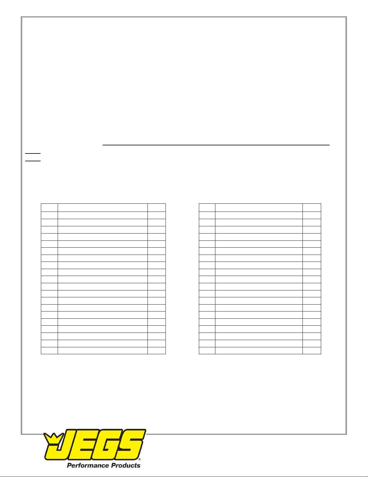
Parts Lists & Diagrams
Main Parts List
Part
Description
Qty.
Part
Description
Qty.
1
Protective Mat
1
21
Hex Bolt M8 x 35
3
2
Lift Table
1
22
Connecting Rod
1
3
Scissor Arm
1
23
Pump Lever
1
4
Roller
4
24
Foot Pedal
1
5
Retaining Ring 12
8
25
Hex Nut M8
10
6
Pin
2
26
Rubber Pad
1
7
Pin
1
27
Locking Swivel Caster 4”
2
8
Retaining Ring 14
2
28
Spring Washer 8
8
9
Base
1
29
Washer 8
8
10
Pin
2
30
Hex Bolt M8 x 16
8
11
Lock Nut M8
2
31
Handle
1
12
Wheel 4"
2
32
Pull Rod
1
13
Bushing
2
33
Control Lever
1
14
Hex Bolt M8 x 60
2
34
Roll Pin
3
15
Ram
1
35
Bolt M8 x 25
1
16
Pin
1
36
Jacket
1
17
Retaining Ring 16
2
37
Spring
1
18
Pin 8 x 40
1
38
Hex Bolt M10 x 30
2
19
Cotter Pin
1
39
Safety Bar
2
20
Bushing
2
40
Hex Nut M10
2
1-800-345-4545 jegs.com
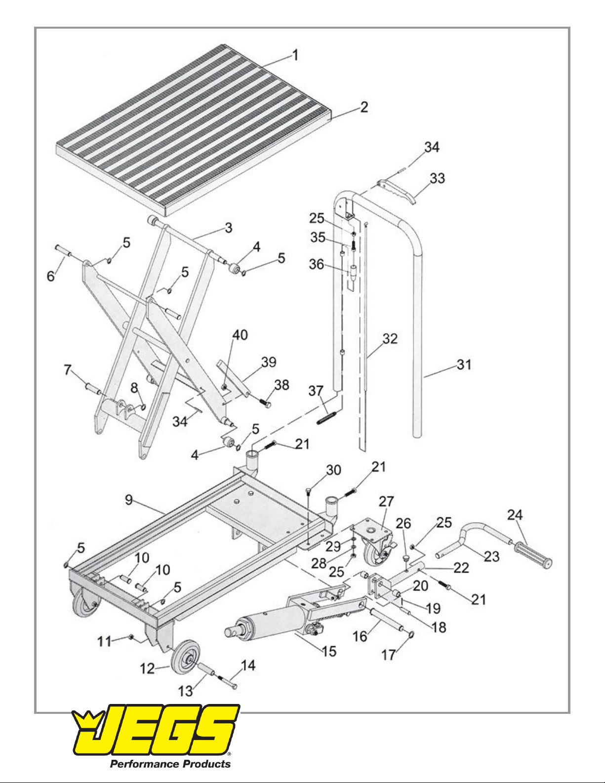
Main Assembly Diagram
1-800-345-4545 jegs.com

Parts List A –Ram
Part
Description
Qty.
Part
Description
Qty.
1a
O-Ring
1
24a
Bolt M8 x 25
1
2a
Top Nut
1
25a
Seal Washer
1
3a
Sealing Gasket
1
26a
Pump Cylinder
1
4a
Fluid Plug
1
27a
U-Cup
1
5a
Fluid Tank
1
28a
O-Ring
2
6a
T-Ring
1
29a
Retainer Ring
1
7a
Cylinder
1
30a
Pump Piston
1
8a
Copper Washer
1
31a
Linkage
1
9a
Ram
1
32a
Pin 8 x 24
1
10a
O-Ring Retainer
1
33a
Spring Cap
1
11 a
O-Ring
1
34a
Spring
1
12a
Base
1
35a
Bolt M8 x 25
1
13a
Spring
1
36a
Plug
1
14a
Release Valve
1
37a
Spring
1
15a
Seal Washer 20
2
38a
Pumping Valve Spindle
1
16a
Axle Sleeve
1
39a
Pumping Valve Seat
1
17a
O-Ring
2
40a
Steel Ball 6.35
1
18a
Screw M8 x 20
1
41a
Steel Ball 5
1
19a
Nut M8
3
42a
Ball Seat
1
20a
Cotter Pin 2.5 x 24
2
43a
Spring
1
21a
Pin
1
44a
O-Ring
1
22a
Release Valve Link
1
45a
Adjusting Bolt
1
23a
Washer 8
2
1-800-345-4545 jegs.com
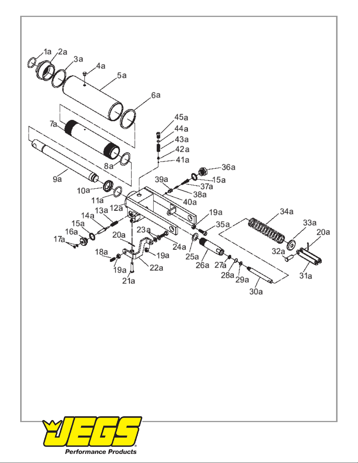
Assembly Diagram A - Ram
1-800-345-4545 jegs.com
Other Jegs Outdoor Cart manuals


