Salford Farm Machinery Ltd. 05-2011
AC2000 Assembly Manual 2011
Table of Contents
General Information
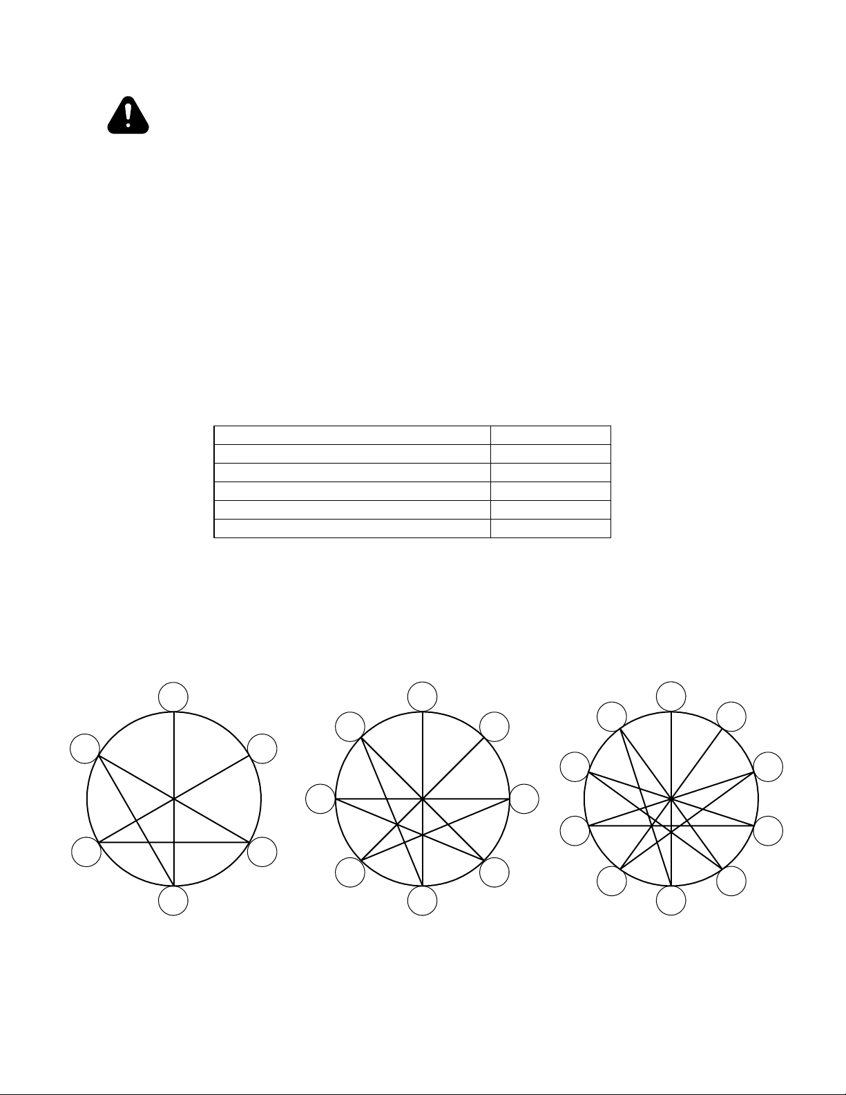
Salford Recommended Torque Values .........................................................................................................5
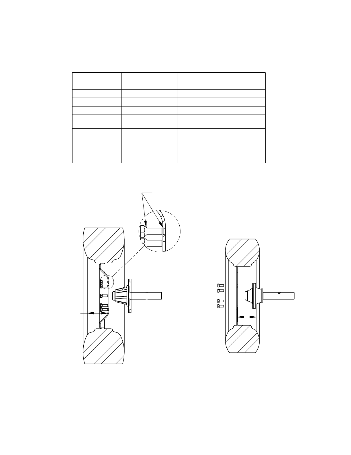
Wheel Torque Specications .......................................................................................................................6
Tire Pressure Ratings ...................................................................................................................................7
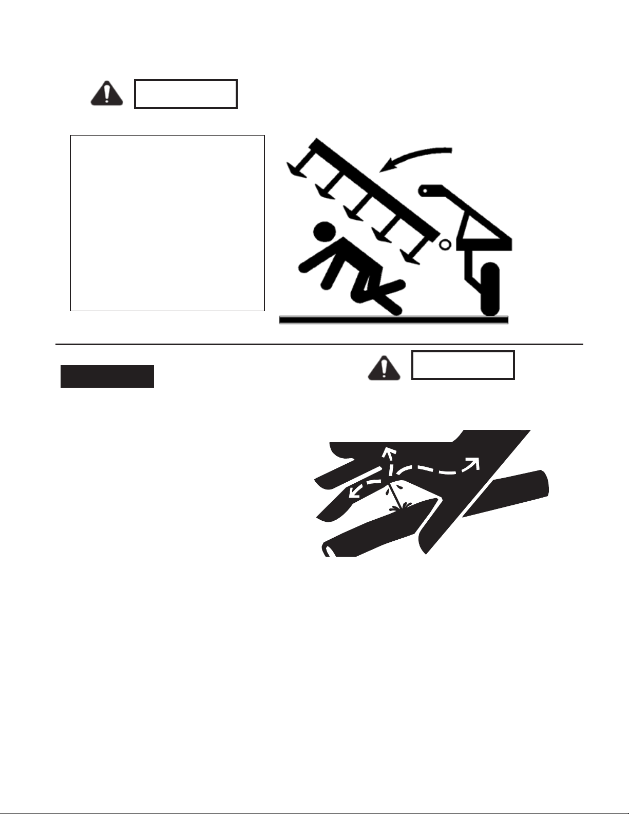
General Safety Precautions ..........................................................................................................................8
Frame Assembly and Wheels
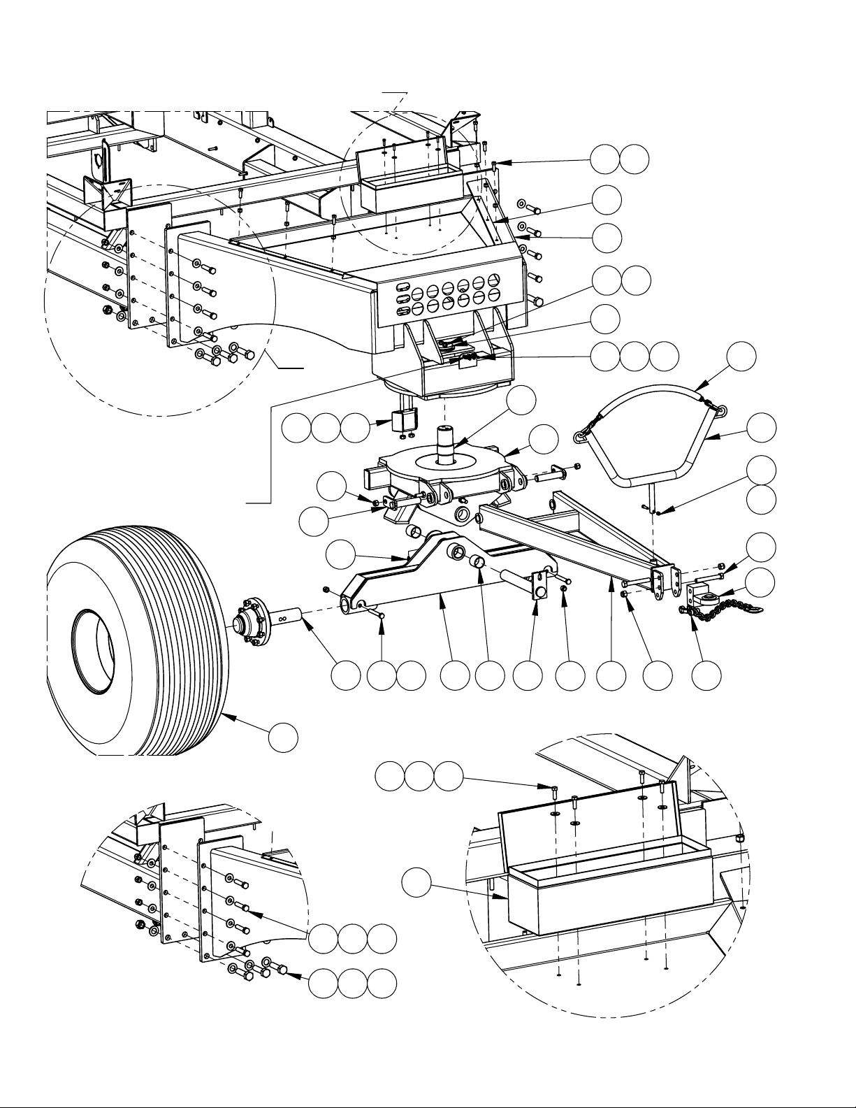
Tow Behind Front End Assembly ..............................................................................................................10
Tow Between Tongue Assembly................................................................................................................12
Hose Holder Assembly ..............................................................................................................................14
Tow Between Toolbox Installation ............................................................................................................15
Tow Behind Rear Tow Hitch......................................................................................................................16
Tow Between Rear Tow Hitch ...................................................................................................................18
Wheels and Axles
16,000 LB Axle Assembly .........................................................................................................................19
20,000 LB Axle Assembly .........................................................................................................................20
8,000 LB Hub and Spindle Assembly........................................................................................................22
16,000 LB Hub and Spindle Assembly......................................................................................................24
20,000 LB Hub and Spindle Assembly......................................................................................................26
Tanks and Platforms
Platform and Ladder ..................................................................................................................................28
Plastic Tank Cradle Assembly....................................................................................................................30
Plastic Tank Inner Ladder Parts .................................................................................................................32
Steel Lid Assembly ....................................................................................................................................34
Meterbox and Drive Installation
Meterbox Installation.................................................................................................................................36
Meterbox Assembly ...................................................................................................................................37
Transmission Mounting .............................................................................................................................40
Zero-Max Handle Installation....................................................................................................................42
Locking Collar Procedures ........................................................................................................................43
Ground Drive Installation ..........................................................................................................................44
Ground Drive Chain Routing.....................................................................................................................47
Hydraulic Drive Installation ......................................................................................................................48
Air Distribution
Tow Between 13” Fan Mounting...............................................................................................................50
Tow Between 17” Fan Mounting...............................................................................................................51
Tow Behind 13” Fan Mounting .................................................................................................................52
Tow Behind 17” Fan Mounting .................................................................................................................53
Tow Behind Air Distribution .....................................................................................................................54
Tow Between Air Distribution ...................................................................................................................56
Loading Augers
8” Auger Installation ..................................................................................................................................58
10” Auger Installation ................................................................................................................................60
8” Auger Parts ............................................................................................................................................62
Sensor Installation
Sensor Installation......................................................................................................................................64