JEHNERT SOUND DESIGN 65400 User manual

JEHNERT Sound Design | Im Michelreis 14 |D-72124 Pliezhausen |Tel. 07127 / 93457-0 |Fax 07127 / 93457-10 |[email protected] |www.jehnert.de
Assembly instruction
Status: 02.11.2023
VW Bus T6
cab system 65400-2
Art. N0. 65400
1
3-Way-Cab system 65400-2
Radio Adjustment Notice:
To achieve the best sound, all settings on the radio (bass, treble, loudness, etc.) should be set to
should be set to zero or neutral.
Installation note:
To avoid vibration noise, secure all wiring harnesses with insulating tape or similar.
Warranty:
As the manufacturer, we warrant these sound systems for 2 years from the date of purchase from the dealer. Within this warranty period, we will, at our
option, repair or replace free of charge all defects that are based on material or manufacturing defects. Excluded from the warranty are damages caused
by improper use or installation, wear and tear or interventions by third parties. The warranty does not cover consequential damage or defects that
only insignificantly impair the value or usability of the sound systems. A warranty obligation is not triggered in the case of damage caused by external
influences. Systems with additional or incorrect mounting holes are excluded from exchange. These are damages to the components that cannot be
repaired.
Installation instructions: Sound system VW Bus T6 Article 65400
Packing List:
2x XE 26 - neodymium tweeter ø 26mm
2x XE 80 - high-end midrange driver, ø 80mm
1x midrange module (right + left) cover: imitation leather in gray or anthracite
2x XM 165 - low-midrange driver„Power-Woofer“ ø 165mm
2x adapter ring for XM 165 part no. 271320-24
2x 3-way crossover VW T6 - item no. 65400 plug&play 2-piece
1x Mounting template for A-pillar
1x mounting kit woofer: 12x countersunk screw M4 x 16 (hexagon)
12x washer 5mm
12x M5 polystop nut
8x pan-head screw 3,9x16
1x mounting kit mid-high: 2x screw M 4 x 25
4x screw M 4 x 40
4x screw M 4 x 45
12x washer ø 12mm
12x nut M4
Optional on order: Vehicle specific radio connection cable for factory VW radio

JEHNERT Sound Design | Im Michelreis 14 |D-72124 Pliezhausen |Tel. 07127 / 93457-0 |Fax 07127 / 93457-10 |[email protected] |www.jehnert.de
Assembly instruction
Status: 02.11.2023
VW Bus T6
cab system 65400-2
Art. N0. 65400
2
1. disassembly of the door panels
1.3. switch unit, starting at the door lock switch,
lever out
1.1. lower the window pane completely.
1.4. remove the screw in the middle of the door panel.
1.9. disconnect original loudspeaker connection and remove factory woofer
(Drill out and remove fastening rivets
->> make sure that the metal pieces do not fall into the inner area of the door.
Tip: stick adhesive tape behind the rivet).
1.2 Unclip the door handle
1.5. lower edge of the door trim:
Unscrew 2x plastic rivets
1.6 Unclip the door trim starting from the bottom by pulling and lift it upwards.
(Clamping strip on the lower edge of the window is still attached).
1.7. unclip door release bowden cable - pull 1cm on the cable sheathing at the opening lever - then unhook.
1.8. unplug connector„alarm light, window regulator and mirror adjustment“.

JEHNERT Sound Design | Im Michelreis 14 |D-72124 Pliezhausen |Tel. 07127 / 93457-0 |Fax 07127 / 93457-10 |[email protected] |www.jehnert.de
Assembly instruction
Status: 02.11.2023
VW Bus T6
cab system 65400-2
Art. N0. 65400
3
2. crossover assembly
The radio must be removed to adapt the input of the crossover.
2.1 Use a plastic wedge to lever off the radio bezel (incl.
ventilation nozzles). lever off with a plastic wedge.
2.2 Remove the 4 Torx screws (TX20) underneath.
Pull out the radio and disconnect the quadlock connector.
2.5. lead the woofer cable to the woofer installation location
through the rubber grommet to the vehicle door.
2.6 Route the mid-range and tweeter cables under the dashboard to
the A-pillar.
2.4. connect speaker cables for tweeter, midrange and woofer to the
to the labeled crossover output (with 6.3mm
crimp connector), mark midrange and tweeter cables.
Wrap crossover with damping fleece or similar, insert right and left
under the dashboard on the right and left side and make sure
and ensure a tight fit (e.g. with cable ties).
Zur Vermeidung von Vibrationsgeräuschen alle Kabelstränge mit Isolierband o.ä. sichern.
2.3 Adapting the loudspeaker cable with the radio
(Radio connections: „Front left“ and„Front right“).
Route cable to crossover mounting location
right and left under the dashboard. Connect cable to
Connect crossover input.

JEHNERT Sound Design | Im Michelreis 14 |D-72124 Pliezhausen |Tel. 07127 / 93457-0 |Fax 07127 / 93457-10 |[email protected] |www.jehnert.de
Assembly instruction
Status: 02.11.2023
VW Bus T6
cab system 65400-2
Art. N0. 65400
4
3. woofer mounting - original installation location in the vehicle doors.
To protect the woofer and adapter ring from water ingress, we recommend attaching a„Rainstop mat“.
(see Fig. 3.1, gray mat under the mounting ring, included in delivery).
3.1. Cut the Rainstop mat to the size of the mounting ring.
and make a circular cut in the lower area.
Place the mounting ring with the Rainstop mat on the factory
opening with the 6 screws supplied (M4 x 20
(M4 x 20 - hexagonal). At the front and rear, shim with
12 mm washers at the front and rear.
Note: After all woofers are connected to the crossover,
the polarity of all woofers should be checked at a 9 volt battery
(on crossover input cable on radio/power amp side):
Pole of FW input + to + of 9 V battery.
Pole of FW input - to - of 9 V battery
Both woofers must resonate evenly during this check!
A reversed polarity of the woofer can cancel the entire bass response!
To avoid vibration noise, secure all cable harnesses with insulating tape or similar.
ATTENTION!!!
The cable connections of the woofer must not come into contact with the inner door panel --> insulate if necessary.
3.2 Connecting the woofers to the crossover network
Low frequency crossover
Connection woofer
Original speaker terminal
3.1 Fasten the mounting ring with 6x M5 x 30 screws, 5mm washers and M5 polystop nuts each (Fig. C). Then fasten the
loudspeaker to the mounting ring with 4x 3.9 x 16 raised countersunk head screws each and connect the original
loudspeaker connector with the JEHNERT loudspeaker connector and the JEHNERT loudspeaker.
C

JEHNERT Sound Design | Im Michelreis 14 |D-72124 Pliezhausen |Tel. 07127 / 93457-0 |Fax 07127 / 93457-10 |[email protected] |www.jehnert.de
Assembly instruction
Status: 02.11.2023
VW Bus T6
cab system 65400-2
Art. N0. 65400
5
4. Dämmung der Fahrzeugtüren und Türverkleidungen
5. mounting the door panels on the vehicle doors.
Important recommendation:
The use of woofers in the door panel causes vibrations due to the oscillations of the bass,
which can lead to rattling noises in the vehicle door:
Measures against vibration noise:
4.1. insulation of the vehicle doors
- Cover the back of the door trim with insulating fleece (Order No. 27000) or foam material.
or
- Stabilize rear side of door trim with stiffening compound (GRP fiber filler or similar).
IMPORTANT: Make sure to leave the cut-outs for the door airbag and speakers free!
- Cover the *backside of the door panel inside (=outer door skin) with self-adhesive
bitumen mats / tar mats (see example below).
- by tapping the vehicle door, vibration noises of door mechanism parts (e.g. Bowden cables etc.)
and localize cable harnesses and wrap them with foam / felt, foam rubber or similar.
- cut off protruding cable ties (rattling noises!)
- glue felt or foam under the original wiring harness
4.2. insulation of the rear side of the door panel
- Apply insulation fleece (Order No. 27000) to the back of the door trim.
or foam
or
- Stabilize the rear side of the door trim with stiffening compound (GRP fiber filler or similar).
IMPORTANT: Make sure to leave the cut-outs for the door airbag and speakers free!
5.1 Hook the door panel into the top of the door shaft strip.
5.2 Reattach the door trim in reverse order.
Ensure that the clips are unlocked, see Fig.
1. first insulation layer with alubutyl mats
2. second insulation layer with insulation fleece mats
Final check after door panel assembly:
Check all functions of controls such as seat adjustment, glove box opening, window regulator, etc.
ATTENTION / Danger !!!
No insulating material behind side airbags
IMPORTANT:
No insulating material behind speakers and door releases. Leave out
fastening clips
!

JEHNERT Sound Design | Im Michelreis 14 |D-72124 Pliezhausen |Tel. 07127 / 93457-0 |Fax 07127 / 93457-10 |[email protected] |www.jehnert.de
Assembly instruction
Status: 02.11.2023
VW Bus T6
cab system 65400-2
Art. N0. 65400
6
6. mounting mid-high module on the A-pillar
6.1 Dismantle the A-pillar.
Tip: To protect the A-pillar against scratches, mask the surface all around with adhesive tape.
10mm
50mm
6.2 Drill holes (5mm Ø) on the back of the A-pillar for the screw anchored in the molded part. The drilling points are located on the refe-
rence point of the factory tweeter mounting.
Bore 5mm
Bore 5mm
Bore 5mm
6.3 Place the enclosed template on the A-pillar, mark the spea-
ker openings and cut them out with a jigsaw. Caution: do not
cut away too much
Screw M4x30
Screw M4x30
Nut and washer
6.4 Align the module on the A-pillar and mount it with
the supplied screws as shown in the illustration. Insert the
screws through the holes previously drilled in the A-pillar
-->> Screw the screws with washer and self-locking nut
and tighten carefully! (Illustration for better representati-
on without speakers)

JEHNERT Sound Design | Im Michelreis 14 |D-72124 Pliezhausen |Tel. 07127 / 93457-0 |Fax 07127 / 93457-10 |[email protected] |www.jehnert.de
Assembly instruction
Status: 02.11.2023
VW Bus T6
cab system 65400-2
Art. N0. 65400
7
Screw M4x20
Screw M4x45
Screw M4x40
6.5 Use the remaining screws to fix the molded part to the A-pillar.
6.6. connect midrange and tweeter to crossover (red or
marked cable =).
6.7 Reassemble the A-pillar trim and
Attach cover panel

JEHNERT Sound Design | Im Michelreis 14 |D-72124 Pliezhausen |Tel. 07127 / 93457-0 |Fax 07127 / 93457-10 |[email protected] |www.jehnert.de
Assembly instruction
Status: 02.11.2023
VW Bus T6
cab system 65400-2
Art. N0. 65400
8
Our team in Pliezhausen will be happy to provide you with advice and assistance at any time:
JEHNERT Sound Design
»Development and production of car audio systems«
Inh. Hans-Peter Jehnert
Im Michelreis 14
72124 Pliezhausen
Tel.: 07127-93457-0
Fax: 07127-93457-10
www.jehnert.de
Notes:
This manual suits for next models
1
Table of contents
Popular Automobile Accessories manuals by other brands

Automatic
Automatic Blue Ox BX1821 installation instructions
DV8
DV8 RBBR-02 installation manual
Thule
Thule Kit 1012 Fitting instructions

American muscle
American muscle 71324 manual
Pyle view
Pyle view PLCM103 instruction manual
Harbor Freight Tools
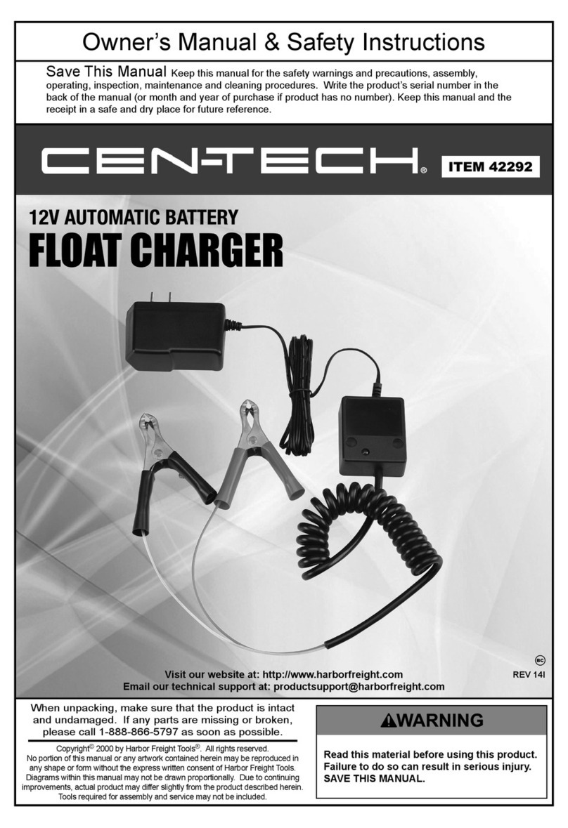
Harbor Freight Tools 42292 Owner's manual and safety instructions
