9
INSTALLATION, WIRING & PROGRAMMING GUIDE
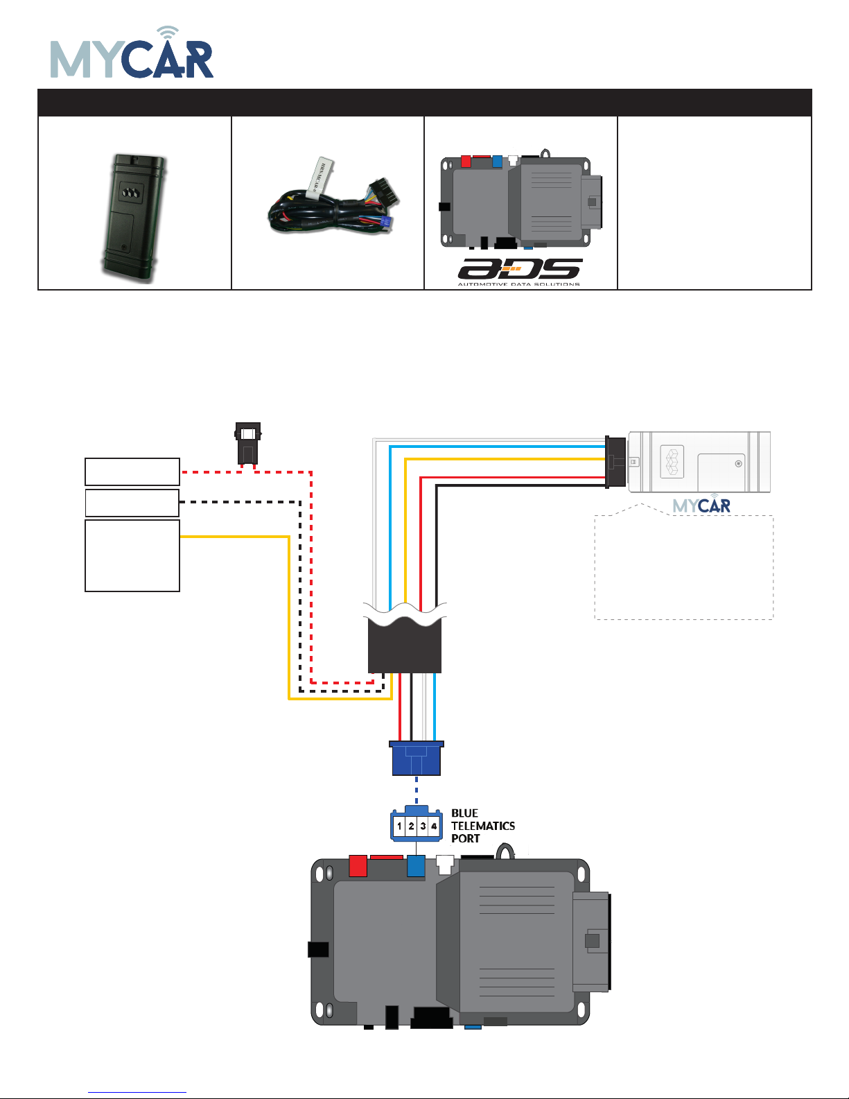
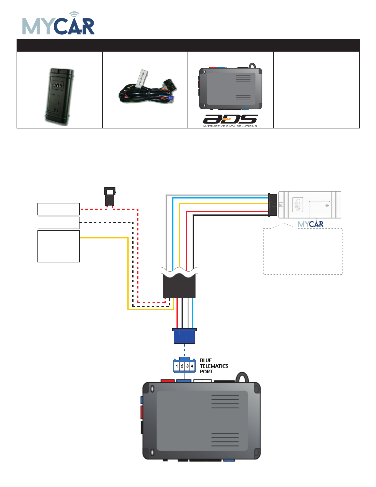
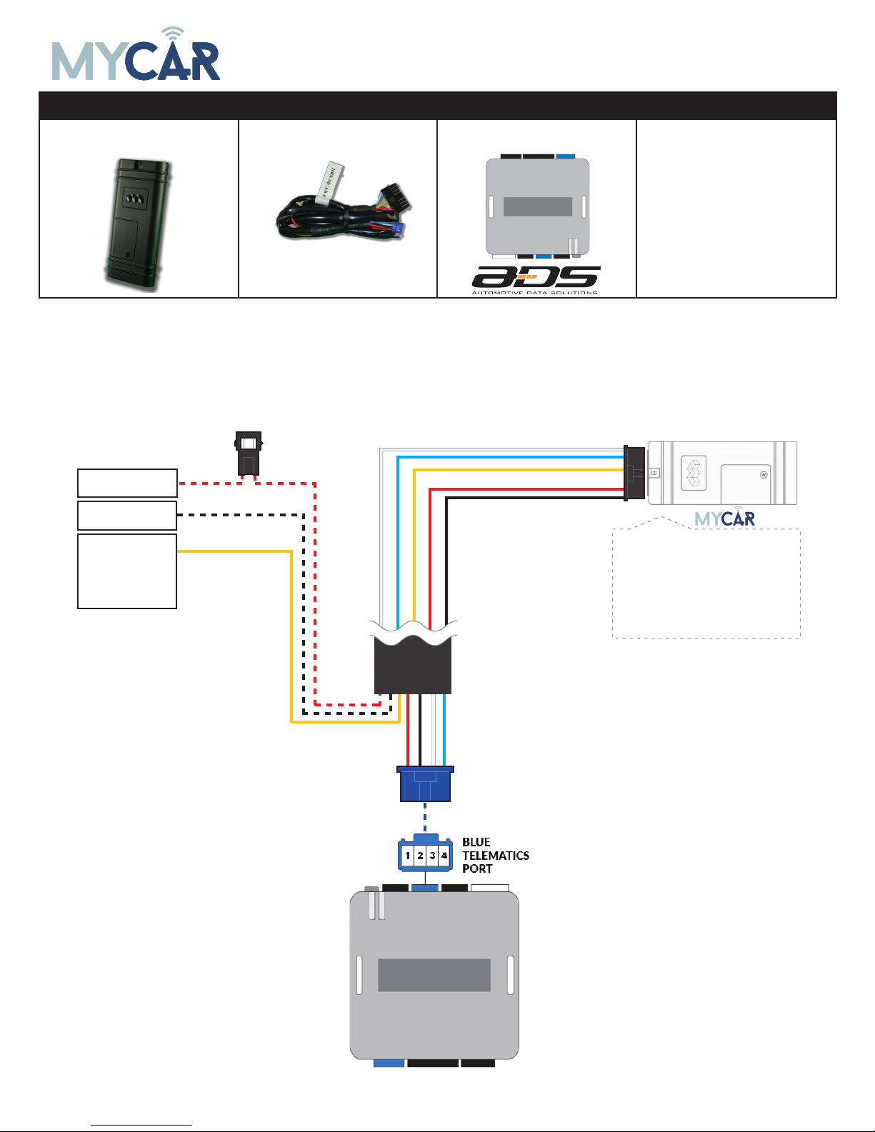
STEP 3. NETWORK CONNECTIVITY
Once the telematics module is connected into the remote starter, two LED’s will display to which networks
you are connected to. (See LED Status Reference Chart on last page for details). NOTE: The vehicle may
need to be outside in an open area in order to connect to a cellular and/or GPS network.
STEP 4. ADD A DEVICE/VEHICLE TO AN ACCOUNT
a. Click the “+” sign at the bottom right of the Application screen. This will allow you to temporarily add
your customers device/vehicle to your personal account.
b. Enter the 16 digit “Serial Number” found at the back of the device (SN: XXXXXX-XXXXXXXXXX) and
Click “Submit the code”.
c. You are now in “Test Mode”. Test Mode will allow you up to 4 hours for you to test the newly in-
stalled device. At any time during this 4 hour period, you can exit testing mode and make unit “Ready
for Customer Delivery” by “Releasing the vehicle” or by “Transfering the vehicle” from your account.
NOTE: If you do NOT remove the vehicle from your account, it will automatically be removed from your
account and make the unit “Ready for Customer Delivery”.
STEP 5. PRE-CONFIGURE MYCAR APPLICATION EXPERIENCE FOR YOUR CUSTOMER
a. Click on the newly added vehicle from the vehicle list to enter the control screen (the screen that will al-
low you to control the vehicle’s remote start functions). This will automatically take you to the “Vehicle
Configuration” page for this vehicle. You will be prompt to “Set a Bypass Protocol” to use this device.
Click “Ok”.
b. Now you must set the protocol for the MyCar device. When combined with the iDatastart BM or BZ
remote starter previously installed, you must set the protocol to “ADS” and click “ACCEPT” then click
“Done” at the top right corner.
c. Now please allow a moment (About 5 minutes) for the MyCar device to update your protocol selection
and reboot. After this wait period it will be available to accept commands from the App. In the vehicle
control screen, the Device Signal icon located above the Stop button will display the connectivity status
of your MyCar device. If the icon is Grayed out, Please wait, Device is still Oine. If icon is Green, Device
is Online and Ready to go.
d. Then from the top right click on of the Settings section edit the Vehicle name, configure the Auxiliaries
that might have been added if applicable and click ACCEPT when done. Then choose the vehicle to dis-
play in the control panel in the VEHICLE IMAGE section and click ACCEPT once done.
e. When your configurations are all completed, click “Done” at the top right corner. All Configurations will
take eect.
STEP 6. TEST YOUR DEVICE
When the system is Online you start testing the unit from the vehicle control panel. Test all the application
functions (Start, Stop, Lock, Unlock, Auxiliaries, ETC.) When done with the testing, from the vehicle list you
can “Release” the vehicle. There are 2x dierent method to release it to the new owner. Choosing “release”
will simply remove it from your account and make it “Ready for Customer Delivery”. Choosing “transfer”
will transfer the device to the new owner’s account.
Also make sure that the MyCar Owners Card is handed to the New Owner of the vehicle. Doing this will
ensure that the instructions on how to setup their App, Account and Vehicle is done correctly by using the
device serial number located on the sticker axed by the installer at the time of installation.