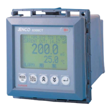
JENCO 6309 POT User manual

OPERATION MANUAL
JENCO MODEL 6309 POT
MICROCOMPUTER BASED
pH /ORP/ Temperature
CONTROLLER
JENCO ELECTRONICS,LTD.

2
CONTENTS Page
I. INITIAL INSPECTION and ASSEMBLY 3
MOUNTING PROCEDURE 3
II. GENERAL INTRODUCTION 4
III. USING THE JENCO MODEL 6309 POT 5
A. FRONT PANEL (Key function illustration) 5
B. MAIN DISPLAY MODE 6
C. REAR CONNECTORS 8
D. TURNING ON/OFF THE INSTRUMENT 10
IV. MODEL 6309 POT MODES 11
A. NORMAL MODE 11
B. CALIBRATION/SETTING MODE 11
How to use the keys 12
a. CHECK PASSWORD 13
b. USER SETTING 14
c. pH CALIBRATION 14
Step by step pH calibration 15
d. pH CONTROL SETTING 16
e. ORP CALIBRATION 17
f. ORP CONTROL SETTING 18
g. CURRENT SETTING 19
h. TEMP. CONTROL SETTING 19
I. RS485-RTU/PASSWORD SETTINGS 20
V. CONTROLLING THE RELAYS 21
A.ISOLATION VOLTAGE 21
B.OUTPUT LOAD 21
C.RELAY ACTION, RELAY SETPOINT,
HYSTERESIS MODE & HYSTERESIS VALUE 21
D. pH RELAYS 22
E. ORP RELAYS 23
F. TEMPERATURE RELAY 23
VI. 4-20 mA OUTPUT 23
A. ISOLATION VOLTAGE 23
B. OUTPUT LOAD 23
C. pH LINEAR TRANSMITTER (mA) OUTPUT 24
D. ORP LINEAR TRANSMITTER (mA) OUTPUT 25
E. pH ANTILOG (mA) OUTPUT 26
VII. RS485 INTERFACE OPERATION 27
A. INTRODUCTION 27
B. PREPARING THR METER 27
VIII.ERROR DISPLAYS AND TROUBLESHOOTING 28
IX. pH BUFFERS 30
X. SPECIFICATIONS 31
XI. WARRANTY 33

3
I. INITIAL INSPECTION and ASSEMBLY
Carefully unpack the instrument and accessories. Inspect for
damages made in shipment. If any damage is found, notify your
Jenco representative immediately. All packing materials should be
saved until satisfactory operation is confirmed.
MOUNTING PROCEDURE
1. Make a cutout on
any panel, with a
thickness of 1/16 in.
(1.5 mm) to 3/8 in.
(9.5mm).
2. Remove the
mounting assembly
from the controller
and insert the
controller into the
cutout.
3. Replace the
mounting bracket
assembly onto the
controller and
secure the
controller to the mounting panel.
Warning:
If the equipment is used in a manner not specified by the
manufacturer, the protection provided by the equipment may be
impaired.
Cleaning the instrument:
1. Be sure to remove the power before attempting to clean the
meter.
2. Use a lint free cloth and clean water or neutral detergent.
3. Wipe the outer surface of the instrument only.
4. Wipe-dry the instrument before powering again.

4
II. GENERAL INTRODUCTION
The Jenco Model 6309 POT (pH, ORP and Temperature) System is
a rugged microprocessor based instrument assembled in a
watertight ¼ DIN case, designed for use in laboratories and process
control applications.
The model 6309 POT microprocessor performs a self-diagnostic
routine every time you turn on the unit providing you with basic
information on the stability of the instrument.
The system simultaneously displays pH, ORP, Temperature, relay
status and current output in one LCD graphic screen.
The model 6309 POT is equipped with 5 relays (2 programmable
high or low relay for pH, 2 programmable high or low relay for ORP
and one programmable high or low relay for temperature); all relays
are hysteresis driven and configurable to CENTER or EDGE mode.
The system also has a isolated 4-20mA analog output, offset and
span configurable for the pH or ORP display.
The model 6309 POT comes with a RS485 interface that can easily
let the user log all data (from multiple model 6308 or 6309) with an
IBM©PC/AT compatible computer. For advanced users, the model
6309 POT may also be remotely controlled from main display mode
to all calibration/setting modes.

5
III. USING THE JENCO MODEL 6309 POT
A. FRONT PANEL
1. The [MODE/-]MODE or CURSOR key.
1a. In Normal mode this key will change the ORP display to
ORP ABS(olute)orORPREL(ative).
1b. In Calibration/ Setting mode this key will move to the
next digit of the current active parameter.
1c. In Calibration/ Setting mode, pressing this key for two
seconds will move you back to the previous parameter.
2.The[CAL / VIEW]key.
2a. Pressing this key for about two seconds, during main
display mode will switch to Calibration/Setting mode.
2b. During Calibration/Setting mode this key will switch to the
next available Calibration/Setting page. Pressing this key at
TEMP. CONTROL SETTING will place the display back to
the MAIN DISPLAY MODE.
MODE CAL.
VIEW
CURSOR
pH RECAL.
6309POT
JENCO

6
1
2
3
4
5
6
7
8
9
1
0
3. The []UP key.
During Calibration/Setting mode this key will increment the
current blinking digit of the active parameter.
4. The [/pH Recal.]DOWN or pH RECALIBRATE key.
4a.During Calibration/Setting mode this key will decrement
the blinking digit of the active parameter.
4b. During pH calibration, you can press this key to
recalibrate the stand (offset) or slope buffer again and again.
5. The []ENTER key.
During Calibration/Setting mode, this key will save the current
modified parameter and move the cursor to the next
parameter.
6. The [ ] LIGHT key.
This key will turn on or turn off the backlight of the LCD.
The backlight will automatically turn off if there is no key
activity after two minutes.
B. MAIN DISPLAY MODE
1. RELAY -
this will show
the status of
the relays. At
Power-ON a
“DISABLED”
message will
be displayed
for about 3
seconds
before going
to “NORMAL”
or “CHECK
STATUS” operation. After exiting the Calibration/Setting pages
and the unit is not password locked, a “FROZEN” message
will be displayed for about three seconds before returning to

7
NORMAL or CHECK STATUS operation. IF no relay is ON then
the “NORMAL” message will be displayed. IF any relay is ON
then the “CHECK STATUS” will be displayed.
2. CURRENT OUT - this will display the actual output of the 4-20
mA output. At POWER-ON this will show “OFF” for about three
seconds before going to normal operation. After exiting the
Calibration /Setting pages a “FROZEN” message will be
displayed for about three seconds before returning to normal
operation.
3. REL or ABS – this text will indicate if the present ORP reading
is ABSolute or RELative value.
4. annunciator - This will be displayed if Calibration/Setting
pages are password locked, meaning the user will not be able
to change the calibration/setting values unless the correct 4 digit
number has been entered.
5. H,Lannunciators - one or both of these annunciators will be
displayed if the left side reading (LARGE FONT DISPLAY)
triggered the respective relay settings. The rightmost character
will indicate RELAY 1 if the display is pH or RELAY 3 if the
display is ORP. The leftmost character will indicate RELAY2 if
the display is pH or RELAY 4 If the display is ORP. If the display
is ORP the annunciators will only indicate the unit selected at the
RELAY/mA option in the ORP CALIBRATION .
6. LARGE FONT DISPLAY - this reading uses the biggest font
and the reading here is the only one that will affect the analog
output. You can select the pH or ORP reading only to be shown
here by changing the Transmitter Output (pH LINEAR, pH
ANTILOG or ORP LINEAR) option.
7. H,Lannunciators - one or both of these annunciators will be
displayed if the left side reading (MEDIUM FONT DISPLAY)

8
triggered the respective relay settings. The rightmost character
will indicate RELAY 1 if the display is pH or RELAY 3 if the
display is ORP. The leftmost character will indicate RELAY2 if
the display is pH or RELAY 4 If the display is ORP. If the display
is ORP the annunciators will only indicate the unit selected at the
RELAY/mA option in the ORP CALIBRATION .
8. MEDIUM FONT DISPLAY- this is the secondary reading and no
analog output is supplied.
9. Hor Lannunciator - one of these annunciators will be displayed
if the temperature reading triggered the temperature relay
setting. Only one RELAY is available for the temperature.
10. Temperature - the current temperature of the solution where the
temperature probe is immersed.
C. REAR CONNECTORS
Before connecting the probes, relays, analog output, RS485 and
power cord be sure that you are inserting to the right terminal as
shown below. Remember that the unit is ON once the user plugs
in the power cord to an AC power supply.

9
1. Connect the AC line to the rear of the instrument. The model
6309 POT can be used with 115 or 230VAC 50/60 Hz. Power
consumption is 6 watts. Make sure the EARTH connector is
connected to the earth lead of the AC power line.
2. Connect the proper load to the output relays. Make sure that the
load does not exceed the relay rating, 5 Amp at 115VAC and
2.5Amp at 230 VAC.
5. Set the proper load to the 4-20mA-output connector. Make sure
that the load impedance is less than 500 Ohms.
CAUTION:
1. MAKE SURE THAT THE POWER IS UNPLUGGED BEFORE
WIRING YOUR PROBES, RELAY ETC.

10
2. MAKE SURE YOU CONNECT THE AC POWER CORD TO THE
CORRECT AC TERMINALS. CONNECTING INCORRECTLY
MAY DAMAGE THE UNIT PERMANENTLY.
D. TURNING ON/OFF THE INSTRUMENT
By just plugging the unit to a correct AC voltage the unit will be
ready for use. There is no Power key so unplugging or plugging the
unit will turn OFF or turn ON the unit respectively.
After the unit is turned on, it will
perform some basic self diagnostics
and will display “OK” or “BAD”. If you
received any “BAD” messages turn
OFF the unit and turn it ON again.
(See VIII. ERROR DISPLAYS AND
TROUBLESHOOTING).
If the message persists then you might
need to call your distributor. (See XI. WARRANTY).
After the self-diagnostic is complete the temperature will be
displayed on the lowest part of the screen and you are ready to
make pH/ORP/Temperature measurements. Just immerse the
probes half way to the liquid. If possible do not allow the probes to
touch any solid object in the solution. There should be no air
bubbles around the probes either. Shaking or moving the probes
vigorously before recording any measurement will dislodge any
bubbles formed in the probes.

11
IV. MODEL 6309 POT MODES
A. NORMAL MODE
Turning ON the unit will always display
main display mode.
This instrument is designed to provide
four distinct measurements:
1. Temperature - current temperature
of the solution, which is always
displayed.
2. pH - the degree of acidity or alkalinity
of the solution (with automatic
temperature compensation).
3. ORP-ABS - a measurement of absolute ORP mV.
4. ORP-REL - a measurement of relative ORP mV. The OFFSET
value at the ORP CALIBRATION will be added to the ORP absolute
value to display the ORP relative value.
You can select which ORP unit to display by pressing the [MODE/-]
key.
ORP (Absolute or Relative), pH and Temperature are always
simultaneously displayed in the graphic LCD screen in normal
mode.
B. CALIBRATION/SETTING MODE
Pressing the [CAL/VIEW] key for about two seconds during main
display mode will bring-up the first page of seven pages of the
Calibration/Setting mode. Pressing [CAL/VIEW] key will switch to
the next page until the last page, where pressing [CAL/VIEW] again
will return the user to main display mode.

12
Below is a simple flowchart showing the path of the [CAL/VIEW]
key:
How to use the keys
1. At MAIN DISPLAY you need to press and hold the [CAL/VIEW]
key for two seconds to change the display to VIEW SETTING PAGE
or if the instrument is password locked the display will be
PASSWORD CHECK page.
(PRESS CAL/VIEW
KEY 2 SECONDS)
MAIN DISPLAY
VIEW/CHANGE PAGE
pH CALIBRATION PAGE
MAIN DISPLAY
CORRECT
PASSWORD
PASSWORD
LOCKED?
pH CONTROL SETTING PAGE
TEMP. CONTROL SETTING PAGE
YES NO
YES
NO
ENTER
PASSWORD
YES
TEMP. CONTROL SETTING PAGE
CONTROLFROZEN
CONTROLNOTFROZEN
CURRENT OUT SETTING PAGE
CURRENT OUT SETTING PAGE
pH CONTROL SETTING PAGE
pH CALIBRATION PAGE
ORP CALIBRATION PAGE
ORP CONTROL SETTING PAGE
ORP CONTROL SETTING PAGE
ORP CALIBRATION PAGE

13
2. At MAIN DISPLAY pressing the [MODE/-] key will toggle
between ABSolute ORP and RELative ORP.
3. You can change any blinking options or digit by pressing the
[]or []keys.
4. For options in digit format you need to press the [MODE/-]
key to move the cursor to the next digit .
5. If you are satisfied with the selection you made you need to
press the []ENTER key to save the changes and move to the
next option.
6. If you don’t need to change the current blinking option just press
the [ ]ENTER key to move to the next selection.
7. You also can press and hold [MODE/-] key for two seconds and
will move back the cursor to the previous option.
a. CHECK PASSWORD
You will only see this page if the
unit is password locked. To change
any settings or calibration you need
to unlock the system to remove the
“PASSWORD LOCKED” message.
You need to enter the correct four
digit number on the “ENTER
PASSWORD” input. You can still
view all the pages of
Calibration/Setting mode if the system is password locked by just
pressing the [CAL/VIEW] key on this page. If the unit is
“PASSWORD LOCKED” going to Calibration/Setting mode will
not affect the function of the relays and analog output.
CAUTION: If the unit is not locked then every time the user enters
the Calibration/Setting mode the relays and analog out will be
frozen.

14
b. USER SETTING
You will only see this page if the unit is
not password locked. This page is just
aWARNING, informing that all relays
and analog output are frozen, and that
you can calibrate and change the
settings.
NOTE: FROZEN MEANS ALL THE RELAYS AND THE ANALOG
OUT WILL MAINTAIN THEIR LAST STATE UNTIL THE USER
RETURNS TO MAIN DISPLAY MODE.
c. pH CALIBRATION
ATC TEMP. – the current
temperature of the solution.
1. BUFFER 1 - in this option you
can select which buffer to use for
the standardization calibration.
You can choose 7.00 pH or
6.86 pH by using the []and
[/pH-Recal.] keys and pressing
the [] key to save your choice.
2. BUFFER 2 - after you selected the buffer 1 this option will let you
select the second buffer to use to calibrate the slope. You can
choose 4.00 pH, 4.01 pH, 9.18 pH or 10.01 pH by using []and
[/pH-Recal.] keys and pressing the [] to save your choice.
3. STAND - this is the actual pH calibration process, this line will
display the buffer to be used for STAND (OFFSET) calibration ,
depending on the choice you made on BUFFER 1 .(SeeStepby
step pH Calibration.)

15
4. SLOPE - this is part 2 of the pH calibration process, this line will
display the buffer to be used for SLOPE calibration, depending on
the choice you made on BUFFER 2. (See Step by step pH
Calibration.)
EFFICIENCY -After saving the SLOPE a new efficiency will be
displayed for about 4 seconds and then will move to the next page.
Efficiency = (new slope/ ideal slope) x 100%
We recommend that you use a new electrode, if the electrode
efficiency is lower than 80%.
Step by step pH calibration
1. Press the [CAL/VIEW] key to go to pH Calibration page. If the unit
is password locked, remove the password lock first.
2. Select buffer 1 (7.00 or 6.86), by using the []or[/pH-Recal.]
keys, then press the [] key to save your selection.
3. Select buffer 2 (4.00,4.01,9.18 or 10.01), by using the []or
[/pH-Recal.] keys, then press the []key to save your selection.
4. Clean the pH electrode and temperature probe with de-ionized or
distilled water.
5. Place the pH electrode and Temperature probe into buffer 1.
6. Press the []key. A “WAIT” message will blink indicating that the
instrument is waiting for a stable reading. The display will be locked
to the buffer value corresponding to the temperature of buffer 1 (See
IX. pH Buffers). When a stable reading is reached, the unit will blink
a“SAVE” message.
7. Press the []key to save the STAND calibration and prepare to
do a SLOPE calibration or press the [/pH-Recal.] key to
recalibrate buffer 1 and repeat from step 6.
If “OVER”or“UNDER”(SeeVIII. ERROR DISPLAYS AND
TROUBLESHOOTING) is displayed or a blinking “SAVE” does not
show after more than few minutes then something is wrong with
your buffer 1 or electrode. Be sure your buffer 1 is correct or change
a new electrode and repeat from step 4.

16
8. Clean the pH electrode and temperature probe with the de-
ionized/distilled water.
9. Place the pH electrode and Temperature probe into buffer 2.
10. Press the []key. A “WAIT” message will blink indicating that
the instrument is waiting for a stable reading. The display will be
locked to the buffer value corresponding to the temperature of buffer
2(SeeIX. pH Buffers). When a stable reading is reached, the unit
will blink a “SAVE” message.
10. Press the [] key to save the SLOPE calibration or press the
[/pH-Recal.] key to recalibrate buffer 2 and repeat from step 8.
If “OVER”or“UNDER”(SeeVIII. ERROR DISPLAYS AND
TROUBLESHOOTING ) is displayed or a blinking “SAVE” does not
show after more than few minutes then something is wrong with
your buffer 2 or electrode. Be sure your buffer 2 is correct or change
a new electrode and repeat from step 4.
11. Set-up your Relay, mA OUT and Temperature control.
12. The unit is ready for measurement and control.
d. pH CONTROL SETTING
1. RELAY1 - The control action
for this relay is changeable, you
can choose “HI”-action or “LO”
action. (In HI-action the relay will
turn ON if the pH is greater than
the RELAY1 set point, in LO-
action the relay will turn ON if the
pH is less than the RELAY1 set
point, which is modified by the
hysteresis value and hysteresis
mode.)(See chapter V. CONTROLLING THE RELAYS .) Use []
and [/pH-Recal.] to change the RELAY1 action then press []
to save. After you select the RELAY1 action you can now select the
RELAY1 set point. Use [] and [/pH-Recal.] keys to change

17
the blinking digit; use the [MODE/-] key to select another digit and
the [] key to save the new set point.
2.RELAY2 - The control action for this relay is changeable, you can
choose “HI”-action or “LO” action. (In HI-action the relay will turn ON
if the pH is greater than the RELAY2 set point, in LO-action the
relay will turn ON if the pH is less than the RELAY2 set point, which
is modified by the hysteresis value and hysteresis mode.)(See
chapter V. CONTROLLING THE RELAYS .) Use [] and [/pH-
Recal.] to change the RELAY2 action then press []to save. After
you select the RELAY2 action you can now select the RELAY2 set
point. Use []and[
/pH-Recal.] keys to change the blinking
digit; use the [MODE/-] key to select another digit and the []keyto
save the new set point.
3. HYSTERESIS (mode) -this is the hysteresis mode for pH
RELAY1 and pH RELAY2. You can choose “CENTER”or
“EDGE”. (See chapter V.CONTROLLING THE RELAYS.)
4. HYSTERESIS (value) - this is the actual value of the hysteresis.
You can change this value from 0.01 pH (Don’t set to 0.00 pH) to
3.99 pH (See V. CONTROLLING THE RELAYS.)
e. ORP CALIBRATION
1. OFFSET - The value here will be
subtracted to the absolute ORP
reading to display the relative ORP
reading.
RmV=AmV-OFFSET
2. RELAY/mA UNIT – this is the unit
that the ORP RELAY3 and ORP
RELAY4 will be based upon. The
ORP Relay 3 and ORP Relay 4 values
for ABS and REL are saved in different eeprom location.
Note: AmV = Absolutue mV, RmV = Relative mV

18
f. ORP CONTROL SETTING
1.RELAY3 - The control action for this
relay is changeable, you can choose
“HI”-action or “LO”action.(InHI-
action the relay will turn ON if the
ORP is greater than the RELAY3 set
point, in LO-action the relay will turn
ON if the ORP is less than the
RELAY3 set point, which is modified
by the hysteresis value and hysteresis
mode.)(See chapter V. CONTROLLING THE RELAYS .) Use []
and [/pH-Recal.] to change the RELAY3 action then press []to
save. After you select the RELAY3 action you can now select the
RELAY3 set point. Use []and[
/pH-Recal.] keys to change the
blinking digit; use the [MODE/-] key to select another digit and the
[]key to save the new set point.
2. RELAY4 - The control action for this relay is changeable, you
can choose “HI”-action or “LO” action. (In HI-action the relay will
turn ON if the ORP is greater than the RELAY4 set point, in LO-
action the relay will turn ON if the ORP is less than the RELAY4 set
point, which is modified by the hysteresis value and hysteresis
mode.)(See chapter V. CONTROLLING THE RELAYS .) Use []
and [/pH-Recal.] to change the RELAY4 action then press []to
save. After you select the RELAY4 action you can now select the
RELAY4 set point. Use [] and [/pH-Recal.] keys to change the
blinking digit; use the [MODE/-] key to select another digit and the
[]key to save the new set point.
3. HYSTERESIS (mode) -this is the hysteresis mode for ORP
RELAY3 and ORP RELAY4. You can choose “CENTER”or
“EDGE”. (See chapter V.CONTROLLING THE RELAYS.)
4. HYSTERESIS (value) - this is the actual value of the hysteresis.
You can change this value from 1 (Don’t set to 0 mV) to 999 AmV or
RmV. ( See chapter V. CONTROLLING THE RELAYS .)

19
g. CURRENT SETTING
1. TRANSMITTER OUTPUT –
This option would let you choose
if the current output type is pH
LINEAR, pH ANTILOG or ORP
LINEAR. If the user chooses
“ORP LINEAR”, the ORP analog
output will be based on the
RELAY/mA UNIT.
2. 4mA OUT – This value will be used in conjunction with 20 mA to
plot the current output. (See chapter VI.4-20 mA OUTPUT.)
3. 20mA OUT – This value will be used in conjunction with the 4 mA
value to plot the output. (See chapter VI.4-20 mA OUTPUT.)
Example: For ORP LINEAR: If 4mA OUT is set at 200AmV, 20mA
OUT is set at 1000AmV, the analog out at 400AmV=
ANALOG OUTPUT = 4mA + (16mA)/(1000AmV-200AmV)
=6mA
h. TEMP. CONTROL SETTINGS
1. RELAY 5 –
The temperature has only
one relay to control you need
to set what control type it will
use, HIGH or LOW type. (In
HIGH-type, RELAY5 will turn
ON if the temperature is
greater than the RELAY5
setting, in LOW-type, the
RELAY5 will turn ON if the
temperature is less than the
RELAY5 setting, which is modified by the hysteresis value and
hysteresis mode.
TEMP.CONTROL SETTINGS
1.RELAY 5 :HIGH
2.SET POINT :100.0 C
3.HYSTERESIS:EDGE
*
SAVING
*
4.HYSTERESIS:
1.0C

20
2. SET POINT -ThisistheRELAY5 control set point.
Note: The user can set the SET POINT from 0.0 to 199.9°C, but
be reminded that the range of the temperature is –10.0 to 120°C.
3. HYSTERESIS - This is the hysteresis mode for temperatur relay.
You can choose “CENTER”or“EDGE”.
4. HYSTERESIS -This is the actual value of the hysteresis. You can
change this value from 0.1 to 19.9°C.
i. RS485-RTU/PASSWORD SETTINGS
1. PARITY –
This option would let you
choose if the current RS-485
type is “EVEN”, “NONE” or
“ODD”.
2. RS485-RTU ID –Thisis
the unique ID/Address for
the unit. If you are
connecting multiple model
6309PDTF or other Jenco models for logging purposes then this
ID/Address must be unique for each connected unit. This
ID/Address is the same address that must be used by the PC
program to communicate with this unit.
3. PASSWORD - This is your security code if the unit is locked
(protected) the value here will not be available. You need to input
the correct code in the PASSWORD CHECK page.
CAUTION: The user is responsible for remembering their
password number, otherwise the user would not be able to
calibrate or change all the settings.
RS485-RTU/PASSWORD
1.PARITY :NONE
SETTINGS
2.RS485-RTU ID:01
3.PASSWORD :0000
Table of contents
Other JENCO Temperature Controllers manuals
Popular Temperature Controllers manuals by other brands
Helios
Helios EHR-R TR Series Fitting and operating instructions
Cisco
Cisco Meraki MT10 installation guide

Siemens
Siemens QAX30.1 quick start guide
Heimeier
Heimeier Multibox K-RTL Installation and operating instructions

White Rodgers
White Rodgers 1050 installation instructions

Rollei
Rollei Smart Temperature and Humidity Sensor user manual

