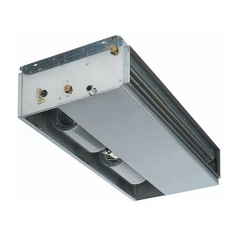
MAXA i-SHWAK V4 06 Use and care manual

INVERTERAIR/WATERCHILLERSANDHEATPUMPS
WITHFLOOR‐STANDINGINDOORUNITANDREMOTECONDENSING
OUTDOORUNIT
USER’SANDINSTALLER’SMANUAL
Models
i‐SHWAKV406/i‐SHWAKV408
i‐SHWAKV410/i‐SHWAKV412
i‐SHWAKV414/i‐SHWAKV414T
i‐SHWAKV416/i‐SHWAKV416T
IndoorunitMod.MAR/MARPOutdooruniti‐SHWAKV4
Thismanualhasbeencreatedforinformativepurpose.Thecompanydeclinesanyresponsibilityfortheresultsofanyprojectingoranyinstallationbasedontheexplanationsand/oronthetechnicalspecifications
providedinthismanual.Itisbesidesforbiddenthereproductionunderanyformofthetextsandofthefigurescontainedinthismanual.
"Thismanualisatranslationfromtheofficialitalianlanguageversion.ForreasonsofenvironmentalrespecttheCompanywillnotprovidethehardcopyintheoriginallanguagewhichcouldbedirectlyrequestedor
downloadedfromtheCompanywebsiteatanytime.Incaseofanydispute,theoriginallanguagemanualwillbethetrustedone".

i‐SHWAKV4Inverterair/waterchillersandheatpumpswithfloor‐standingandremotecondensingunits
1
0709‐2020AL.BA.R.Updateofdiagramscircuits
0605‐2020A.P.A.R.Variedpipes“HPcounter‐current”.Correctionofperformancedata
0512‐2019A.R.A.R.Updateofparagraph8.6–Refrigerantpipingconnections
0407‐2008AL.B.A.R.Updateoftechnicaldataandcharacteristics
0305‐2018AL.B.A.R.UpdateofsolarspecificationsandDHW‐Rkit
0210‐17AL‐BP.FUpdatingoftechnicaldataandaddingthenewmodeli‐SHWAKV416
0106‐2017AL.BP.F.Updatingofexpansionvesselskitandtechnicaldata
0002‐2017AL.B.A.B. ‐‐
RevDateAuthorSupervisorNotes
Catalogo/Catalogue/Katalog/Catalogue
MUI14110H8020‐07
Serie/Series/Serie/Serie/Série
INVERTERAIR/WATERCHILLERSANDHEATPUMPSWITH
FLOOR‐STANDINGANDREMOTECONDENSINGUNITS
Possiblewastedelectricalorelectronicdevices/productsshouldnotbelocatedtogetherwithnormaldomesticwaste,butdisposedaccordingtothe
currentWEEElawincompliancewiththeEuropeanDirective2012/19/UE.PleaseinformyourselfatyourlocalAdministrationoratyourresellerincase
theproductwillbereplacedwithasimilarone.

i‐SHWAKV4MinichillerInverterDuo
2
CECONFORMITYDECLARATION
DICHIARAZIONEDICONFORMITÁCE
THECOMPANYADVANTIXS.P.A–VIASANGIUSEPPELAVORATORE,24–LOC.LAMACIAZ.A.I.–37040–ARCOLE‐VERONA‐ITALY
LASOCIETÀADVANTIXS.P.A–VIASANGIUSEPPELAVORATORE,24–LOC.LAMACIAZ.A.I.–37040–ARCOLE‐VERONA‐ITALY
DECLARES
DICHIARA
thattheunit:
chelamacchina:
Definition
Definizione:
Airtowaterreversibleheatpumpwithremotecondenserunit/
Pompadicalorearia‐acquareversibileconunitàcondensanteremota
ModelN°:
N°modello:
i‐SHWAK/V406/08/10/12/14/16
MAR/MARS/MARP/MARPS
SerieN°:
N°diserie:
MEETSTHEREQUIREMENTSOFDIRECTIVE2006/42/CE
ÈCONFORMEAIREQUISITIDELLADIRETTIVA2006/42/CE
1. TheunitisinCAT.I,soit’sfreefromtheapplicationofDirective2014/68/UE(ReferencetoArt.I,paragraph2,pointf)
L’attrezzaturaapressionerientranellaCAT.I.L’unitàèquindiesentedall’applicazionedellanormativaPED2014/68/UE(RiferimentoArt.I,paragrafo2puntof).
2. Harmonizedstandardsappliedtodesigningandmanufacture:UNIEN378‐1,UNIEN378‐2,UNIEN12735‐1
Normearmonizzateapplicateallaprogettazioneedallacostruzione:UNIEN378‐1,UNIEN378‐2,UNIEN12735‐1
3. OthersEuropeanDirectivesandharmonizedstandardsappliedtotheequipment:2014/35/UE,2014/30/UE,2011/65/UE,2012/19/UE,CEIEN60335‐2‐40,CEI
EN55014‐1,CEIEN55014‐2,CEIEN61000‐3‐2,CEIEN61000‐3‐3,CEIEN62233
EventualialtreDirettiveEuropeeenormearmonizzateapplicateall’attrezzatura:2014/35/UE,2014/30/UE,2011/65/UE,2012/19/UE,CEIEN60335‐2‐40,CEIEN
55014‐1,CEIEN55014‐2,CEIEN61000‐3‐2,CEIEN61000‐3‐3,CEIEN62233
Themanufacturerstates,also,thatthetechnicalfileiscompiledandkeptatADVANTIXSpAandthattheTechnicalManagerPaoloFerroliisthepersonauthorized
tocompileit.
IlfabbricanteinoltredichiaracheilfascicolotecnicodellamacchinaècostituitoecustoditopressoADVANTIXSpAecheilDirettoreTecnicoPaoloIng.Ferrolièla
personaautorizzataacostituiretalefascicolo.
NOME / NAME / VORNAME / NOM / NOMBRE PAOLO
COGNOME / SURNAME / NACHNAME / PRENOM / APELLIDO FERROLI
POSIZIONE / COMPANY POSITION / POSITION / FONCTION / POSICION RESP. TECNICO
Arcole, Gennaio/January 2019

i‐SHWAKV4Inverterair/waterchillersandheatpumpswithfloor‐standingandremotecondensingunits
3
INDEX
1PURPOSESANDCONTENTSOFTHEMANUAL.........................................................................................5
1.1CONSERVATIONOFTHEMANUAL.......................................................................................................................................................5
1.2GRAPHICSYMBOLS..............................................................................................................................................................................5
2SAFETYLAWS.........................................................................................................................................5
3PERMITTEDUSES....................................................................................................................................5
4GENERALSAFETYGUIDELINES................................................................................................................6
4.1HEALTHANDSAFETYOFWORKERS.....................................................................................................................................................6
4.2PERSONALPROTECTIONEQUIPMENT.................................................................................................................................................6
4.3SAFETYSYMBOLS.................................................................................................................................................................................7
4.4REFRIGERANTSAFETYDATASHEET.....................................................................................................................................................7
5GENERALCHARACTERISTICS...................................................................................................................8
5.1AVAILABLEMODELS............................................................................................................................................................................8
5.2MAR.....................................................................................................................................................................................................8
5.3MARP...................................................................................................................................................................................................8
5.4MARS/MARPS......................................................................................................................................................................................9
6TECHNICALCHARACTERISTICS................................................................................................................9
6.1FRAME.................................................................................................................................................................................................9
6.2REFRIGERANTCIRCUIT........................................................................................................................................................................9
6.3COMPRESSORS....................................................................................................................................................................................9
6.4AIRSIDEEXCHANGERS.........................................................................................................................................................................9
6.5FANS..................................................................................................................................................................................................10
6.6USERHEATEXCHANGERS..................................................................................................................................................................10
6.7ELECTRICBOX....................................................................................................................................................................................10
6.8CONTROLSYSTEM.............................................................................................................................................................................10
6.9MONITORINGANDPROTECTIONDEVICES........................................................................................................................................10
6.10HYDRAULICCIRCUIT..........................................................................................................................................................................10
6.11FANSPEEDCONTROLLER...................................................................................................................................................................10
7DESCRIPTIONOFTHEINDOORUNITCODE...........................................................................................11
7.1OPTIONALACCESSORIES...................................................................................................................................................................15
8INSTALLATION......................................................................................................................................16
8.1GENERALITY.......................................................................................................................................................................................16
8.2LIFTINGANDHANDLING....................................................................................................................................................................16
8.2.1Indoorunit........................................................................................................................................................................16
8.2.2Outdoorunit.....................................................................................................................................................................17
8.3LOCATIONANDMINIMUMTECHNICALCLEARANCES.......................................................................................................................17
8.3.1Indoorunit........................................................................................................................................................................17
8.3.2Outdoorunit.....................................................................................................................................................................17
8.4HYDRAULICCONNECTIONS...............................................................................................................................................................18
8.4.1Plant’swatercharacteristics............................................................................................................................................19
8.4.2Hydrauliccircuit................................................................................................................................................................19
8.4.3Connections’positions......................................................................................................................................................20
8.4.3.1Indoorunit.....................................................................................................................................................................................20
8.4.3.2Outdoorunit..................................................................................................................................................................................20
8.4.4Drainagesystemconnection............................................................................................................................................20
8.4.4.1Indoorunit.....................................................................................................................................................................................20
8.4.4.2Outdoorunit..................................................................................................................................................................................21
8.4.5Connectionofthereliefvalve’sdischarge........................................................................................................................21
8.4.6Plantcircuitloading..........................................................................................................................................................21
8.4.7Plantcircuitunloading......................................................................................................................................................22
8.5INDICATIVEDIAGRAMSOFTHEPLANTCIRCUIT................................................................................................................................22
8.5.1Standardschematicdiagramoftheplant........................................................................................................................22
8.5.2SchematicdiagramoftheplantwithDHWrecirculation.................................................................................................23
8.5.3Particularschematicdiagramtypeoftheplantwithhydraulicseparatorandmixingvalve...........................................23
8.6REFRIGERANTCONNECTIONS............................................................................................................................................................24
8.6.1Refrigerantdiagrami‐SHWAKV406,08..........................................................................................................................26
8.6.2Refrigerantdiagrami‐SHWAKV410,12..........................................................................................................................26
8.6.3Refrigerantdiagrami‐SHWAKV414,14Tand16T..........................................................................................................27
8.7ELECTRICALCONNECTIONS...............................................................................................................................................................27
8.7.1Indoorunit........................................................................................................................................................................28
8.7.1.1Connectionterminals.....................................................................................................................................................................29
8.7.2Outdoorunit.....................................................................................................................................................................30
8.7.2.1Connectionterminals.....................................................................................................................................................................30
8.7.3Wiringbetweenindoorandoutdoorunits.......................................................................................................................31
8.7.4Removaloftheoutdoorunit’stopcoverforgettingaccesstotheterminalblockandelectricbox................................31
8.7.5Safetythermostats...........................................................................................................................................................31

i‐SHWAKV4Inverterair/waterchillersandheatpumpswithfloor‐standingandremotecondensingunits
4
9STARTUP..............................................................................................................................................32
10INDICATIONSFORTHEUSER.................................................................................................................32
11SHUTDOWNSFORLONGPERIODS........................................................................................................33
12MAINTENANCEANDPERIODICCHECKS................................................................................................33
12.1ENVIRONMENTALPROTECTION........................................................................................................................................................34
13DISPOSAL.............................................................................................................................................34
14TECHNICALDATA..................................................................................................................................35
14.1PERFORMANCEDATA........................................................................................................................................................................35
14.2OUTDOORUNITS...............................................................................................................................................................................36
14.3INDOORUNITS...................................................................................................................................................................................37
14.3.1ModelsMAR/MARS..........................................................................................................................................................37
14.3.2ModelsMARP/MARPS......................................................................................................................................................38
15ELECTRICDATA.....................................................................................................................................39
15.1MAXIMUMPOWERCONSUMPTION/MAXIMUMINPUTCURRENTOFTHEINDOORUNITS06‐08...................................................39
15.1MAXIMUMPOWERCONSUMPTION/MAXIMUMINPUTCURRENTOFTHEINDOORUNITS10‐12...................................................40
15.2MAXIMUMPOWERCONSUMPTION/MAXIMUMINPUTCURRENTOFTHEINDOORUNITS14‐16....................................................41
16PLANTSIDEHYDRAULICCIRCUITAVAILABLEHEADPRESSURES............................................................42
17READINGOFTHEINDOORUNITMANOMETERS...................................................................................44
18DHWINSTANTANEOUSPREPARER.......................................................................................................44
18.1SECONDARYCIRCUITLOADLOSSES(TODHW‐R)...........................................................................................................................................45
19SOLARGROUP(MODELS:MARS/MARPS).............................................................................................45
19.1CIRCULATORCURVES........................................................................................................................................................................46
19.2LOADINGOFTHEPLANTCIRCUIT......................................................................................................................................................46
19.3MAINTENANCEOFTHECIRCULATOR................................................................................................................................................47
19.4REGULATIONOFTHEFLOWRATEOFHEATTRANSFERFLUIDINTHEPANELS...................................................................................47
19.5TECHNICALCHARACTERISTICS...........................................................................................................................................................47
19.6INTEGRATEDSECURITYSYSTEMSINTHECONTROL...........................................................................................................................47
20OPTIONALDHWTECHNICALSIDEBOILERKIT.......................................................................................48
21OPERATIONLIMITS...............................................................................................................................48
21.1EVAPORATORWATERFLOWRATE...............................................................................................................................................................48
21.2CHILLEDWATERPRODUCTION(SUMMEROPERATION)....................................................................................................................................48
21.3HOTWATERPRODUCTION(WINTEROPERATION)...........................................................................................................................................49
21.4AMBIENTAIRTEMPERATURE.....................................................................................................................................................................49
22CORRECTIONFACTORSFOROPERATIONWITHGLYCOL........................................................................50
23DIMENSIONS........................................................................................................................................50
23.1INDOORUNITS...................................................................................................................................................................................50
23.2OUTDOORUNITS...............................................................................................................................................................................51
23.2.1Models:i‐SHWAKV406/08..............................................................................................................................................51
23.2.2Models:i‐SHWAKV410/12..............................................................................................................................................51
23.2.3Models:i‐SHWAKV414/14T/16/16T...............................................................................................................................51
24ACCESSPROCEDURETOINTERNALPARTS............................................................................................52
24.1INDOORUNIT....................................................................................................................................................................................52
24.2OUTDOORUNIT.................................................................................................................................................................................52
24.2.1Models:i‐SHWAKV406/08............................................................................................................................................52
24.2.2Models:i‐SHWAKV410/12............................................................................................................................................53
24.2.3Models:i‐SHWAKV414/14T/16/16T..........................................................................................................................53
25COMPONENTSOFINDOORANDOUTDOORUNITS...............................................................................54
25.1INDOORUNITMODELSMAR/MARSANDADDITIONALKIT.....................................................................................................................54
25.2INDOORUNITMODELSMARP/MARPSANDADDITIONALKIT.........................................................................................................................55
25.3INDOORUNITTEMPERATURESENSORS.........................................................................................................................................................57
26FILTERCLEANING..................................................................................................................................57
27WIRINGDIAGRAMS..............................................................................................................................58
27.1INDOORUNITELECTRICBOXLAYOUT................................................................................................................................................58
28CONTROLLOGICS.................................................................................................................................58
29HANDBOOKFORSOMECONFIGURATIONSOFINSTALLATION..............................................................58

i‐SHWAKV4Inverterair/waterchillersandheatpumpswithfloor‐standingandremotecondensingunits
5
Thismanualcollectsallthenecessaryinformationforthebetteruseoftheequipmentundersafetyconditionsfortheoperator
thusmeetingtherequirementslistedinthe2006/42/CEEquipmentDirectiveandfollowingamendments.
Note:Allthepicturesinthismanualareforexplanationpurposeonly.Theymaybeslightlydifferentfromtheunityoupurchased.
Theactualshapeshallprevail.
1PURPOSESANDCONTENTSOFTHEMANUAL
Thismanualprovidesbasicinformationasfortheselection,installation,operationandmaintenanceofthe“i‐SHWAKV4”units.It
isaddressedtotheinstallerandtheuseroftheunit:itallowsthisequipmenttooperateefficiently,eveniftheuserdoesnothave
anypreviousspecificknowledgeofit.
Thismanualdescribesthecharacteristicsoftheequipmentwhenitwasbeingputonthemarket;therefore,itmaynotcapture
latertechnologicalimprovementsintroducedbythecompanyaspartofitsconstantendeavourtoenhancetheperformance,
ergonomics,safetyandfunctionality.
Thecompanyintroducesalsotechnologicalimprovementsandisnotconstrainedtoupdatethemanualsforpreviousversionsof
appliancesthatcouldnotbecompatible.Somakesuretouse,fortheinstalledunit,thesuppliedmanual.
It’srecommendedthat,theusermustfollowtheinstructionscontainedinthisbooklet,especiallythoseconcerningthesafetyand
routinemaintenance.
1.1 CONSERVATIONOFTHEMANUAL
Themanualhastobealwayskeptbytheuserforfuturereferences.Ithastobestoredinasafeplace,awayfromthedustand
moisture.Ithastobeaccessibletoalluserswhoshallconsultitanytimetheyareindoubtonhowtooperatetheequipment.
Thecompanyreservestherighttomodifyitsproductsandrelatedmanualswithoutnecessarilyupdatingpreviousversionsofthe
referencematerial.Itdeclinesalsoanyresponsibilityforpossibleinaccuraciesinthemanualifduetoprintingortranscription
errors.
Thecustomershallstoreanyupdatedcopyofthemanualorpartsofitdeliveredbythemanufacturerasanattachmenttothis
manual.
Thecompanyisavailabletogiveanydetailedinformationaboutthismanualandtogiveinformationregardingtheuseandthe
maintenanceofitsownunits.
1.2 GRAPHICSYMBOLS
Indicatesoperationsthatcanbedangerousforpeopleand/ordisruptsthecorrectoperationoftheequipment.
Indicatesprohibitedoperations.
Indicatesimportantinformationthattheoperatorhastofollowinordertoguaranteethecorrectoperationofthe
equipmentincompletesafety.Itindicatesalsogeneralnotes.
2SAFETYLAWS
The“i‐SHWAKV4”units weredesignedincompliancewiththefollowingDirectivesandHarmonisedNorms:
2006/42/CE,2014/35/UE,2014/30/UE,2011/65/UE,2012/19/UECommunityDirectives
UNIEN378‐1,378‐2,UNIEN12735‐1Norms
CEIEN60335‐2‐40Norm
CEIEN55014‐1,CEIEN55014‐2,CEIEN61000‐3‐2,CEIEN61000‐3‐3,CEIEN62233Norms
Andthefollowingdirectivesandregulationsconcerningtheenergylabellingandtheeco‐friendlyproducts:
Communitydirective2009/125/CEandsubsequenttranspositions
Communitydirective2010/30/UEandsubsequenttranspositions
RegulationUENo811/2013
RegulationUENo813/2013
3PERMITTEDUSES
Thecompanyexcludesanycontractualandextra‐contractualliabilitiesfordamagescausedtopersons,animalsorobjects,by
incorrectinstallation,settingandmaintenance,improperuseoftheequipment,andthepartialorsuperficialreadingofthe
informationcontainedinthismanual.
Theseunitshavebeendesignedonlyforheatingand/orcoolingwater.Anyotherusenotexpresslyauthorizedbythe
manufacturerisconsideredimproperandthereforenotallowed.
Thelocationoftheplant,thehydraulicandelectricalcircuitsmustbeestablishedbytheplantingdesignerandmusttakeinto
accountbothtechnicalrequirementsaswellasanyapplicablelocallawsandauthorizedspecifications.
Theexecutionofallworksmustbeperformedbyskilledandqualifiedpersonnelandcompetentintheexistingrulesinthe
countryinwhichtheappliancewillbeinstalled.

i‐SHWAKV4Inverterair/waterchillersandheatpumpswithfloor‐standingandremotecondensingunits
6
4GENERALSAFETYGUIDELINES
Beforebeginningtooperateoni‐SHWAKV4unitseveryuserhastobeperfectlyknowledgeableaboutthefunctionsofthe
equipmentanditscontrolsandhastohavereadandunderstoodtheinformationlistedinthismanual.
It’sstrictlyforbiddentoremoveand/ortamperwithanysafetydevice.
Childrenorunassisteddisabledpersonsarenotallowedtousetheappliance.
Donottouchtheappliancewhenbarefootorpartsofthebodyarewetordamp.
Donotcleantheunit
w
henthepowersupplyis‘ON’.
Donotpull,removeortwisttheelectricalcablescomingoutfromtheunit,evenifitisdisconnectedfromthemain
powersupply.
Donotstepwithyourfeetontheappliance,sitdownand/orplaceanytypeofobject.
Donotsprayorpourwaterdirectlyontheunit.
Donotdisposeof,abandonorleavewithinreachofchildrenpackagingmaterials(cardboard,staples,plasticbags,
etc)astheymayrepresentanenvironmentalandlifehazard.
Anyroutineand
/
ornot‐routinemaintenanceoperationshallbecarriedoutwhentheequipmenthasbeenshutdown,
disconnectedfromelectricandpneumaticpowersourcesandafteritspneumaticsystemhasbeendischarged.
Donotputneitheryourhandsnorinsertscrewdrivers,spannersorothertoolsintomovingpartsoftheequipment.
Theequipmentsupervisorandthemaintenancemanhavetoreceivesuitabletrainingfortheperformanceoftheir
tasksinsafety.
Operatorshavetoknowhowtousepersonalprotectivedevicesandhavetoknowtheaccident‐preventionguidelines
containedinnationalandinternationallawsandnorms.
4.1 HEALTHANDSAFETYOFWORKERS
TheEuropeanCommunityhasadoptedanumberofdirectivesonworkplace’shealthandsafety,whichinclude89/391/CEE,
89/686/CEE,2009/104/CE,86/188/CEEand77/576/CEEdirectives.Everyemployershallimplementsuchprovisionsandensure
thatworkersrespectthem:
Donottamperwithorreplacepartsoftheequipmentwithoutthespecificconsentofthemanufacturer.The
manufacturershallhavenoresponsibilitywhatsoeverincaseofunauthorisedoperations.
Usingcomponents,expendablematerialsorsparepartsthatdonotcorrespondtothoserecommendedbythe
manufacturerand/orlistedinthismanualmaybedangerousfortheoperatorsand/ordamagetheequipment
Theoperator’sworkplacehastobekeptclean,tidyandfreefromobjectsthatmaypreventfreemovements.
Appropriatelightingoftheworkplaceshallbeprovidedsoastoallowtheoperatortocarryouttherequired
operationssafely.Poorortoostronglightingcancauserisks.
Ensurethatworkplacesarealwaysadequatelyventilatedandthataspiratorsareworking,ingoodconditionandin
compliancewiththerequirementsofthelawsinforce.
TheunitoperateswithR410Arefrigerantgas,whichisagreenhousegasaccordingtotheF‐gasRegulation(EU)517/2014
(mandatoryintheEuropeanarea).ThisRegulation,amongtheprovisions,requiresalloperatorsinterveningingreenhousegas
systemstobeinpossessionofacertificateissuedorrecognizedbythecompetentauthority,attestingtoasuccessfulcompletion
ofanexaminationentitlingthemtocarryoutsuchwork.Inparticular:
Devicecontainsupto3kgofthetotalamountofrefrigerantgas:CategoryIIcertificate.
Devicecontains3kgormorethan3kgofthetotalamountofrefrigerantgas:CategoryIcertificate.
TherefrigerantR410Aingaseousformisheavierthanairandtendstoconcentratehighlyinlittleventilatedenvironmentswhena
leakoccurs.Itsinhalationcancausedizziness,suffocationandcandeveloplethalgasifitbecomesincontactwithopenflamesor
hotobjects,(pleaseseeparagraph4.4“REFRIGERANTSAFETYDATASHEET”).
WearappropriatePersonalProtectiveEquipment(PPE)specifically,glovesandgoggles
Ensurethattheworkplaceiswellventilated.Donotworkinclosedroomsorditcheswithweakaircirculation.
Donotworkontherefrigerantnearopenflamesornearhotparts.
Avoidanyrefrigerantleakageintotheenvironmentandpayparticularattentiontoleakagefrompipesand/or
fittingsafterevacuatingtherefrigerantcircuit.
4.2 PERSONALPROTECTIONEQUIPMENT
Whenoperatingandmaintaining,the“i‐SHWAKV4”units,pleaseadoptthefollowingpersonalprotectiveequipment.
Protectiveclothing:Maintenancemenandoperatorshavetowearprotectiveclothingthatcomplieswiththebasic
safetyrequirementscurrentlyinforce.Incaseofslipperyfloors,usershavetowearsafetyshoeswithnon‐slipsoles.
Gloves:Duringmaintenanceorcleaningoperationprotectiongloveshavetobeused
Maskandgoggles:Respiratoryprotection(mask)andeyeprotection(goggles)shouldbeusedduring
cleaningandmaintenanceoperations.

i‐SHWAKV4Inverterair/waterchillersandheatpumpswithfloor‐standingandremotecondensingunits
7
4.3 SAFETYSYMBOLS
Thesafetysignsindicatedontheunitwhichshouldberespected:
Generalhazard.
Electricshockhazard.
Presenceofmovingorgans.
Presenceofsurfacesthatmaycauseinjures.
Presenceofhotsurfaceswhichcancauseburns.
4.4 REFRIGERANTSAFETYDATASHEET
Name:R410A(50%Difluoromethane(R32);50%Pentafluoroethane(R125).
RISKSINDICATIONS
Majorrisks:Asphyxia
Specificrisks:Therapidevaporationcancausefreezing.
FIRSTAID
Generalinformation:Nevergiveanythingbymouthtoanunconsciousperson.
Inhalation:Outdoorsopenstransport.
Useoxygenorartificialrespirationifnecessary.
Donotgiveadrenalineorsimilardrugs
Eyescontact:Rinsecarefullywithwaterforatleast15minutesandconsultadoctor.
Contactwithskin:Washimmediatelywithplentyofwater.
Takeoffimmediatelythecontaminatedclothes.
FIREPREVENTION
ExtinguishingMedia:Whatever.
Specificrisks:Increaseinpressure.
Specificsmethods: Usewaterspraytocoolcontainers
MEASURESAGAINSTACCIDENTALLEAKAGE
Personalprecautions:Evacuatepersonneltosafeareas.
Provideadequateventilation.
Usepersonalprotectiveequipment.
Environmentalprecautions:Evaporate.
Cleaningmethod:Evaporate.
MANIPULATIONANDSTORAGE
Manipulation:
Action/technicalprecautions:Providesufficientairexchangeand/orexhaustinworkrooms.
Recommendationsforsafeuse:Donotbreathevapoursorspraymist.
Storage:Closetightlyandstoreinacool,dryandwellventilatedplace.
Storeinoriginalcontainer.Incompatibleproducts:explosive,flammablematerials,Organicperoxide
EXPOSURECONTROL/PERSONALPROTECTION
Controlparameters: AEL(8‐he12‐hTWA)=1000ml/m³foreachofthetwocomponents.
Respiratoryprotection:Forrescueandmaintenanceoperationinstoragetanksuseself‐containedrespiratorapparatus.
Thevapoursareheavierthanairandcancausesuffocationbyreducingoxygenavailableforbreathing.
Eyesprotection: Safetyglasses.
Protectionofhands:Rubbergloves.
Hygienemeasures:Donotsmoke.
PHYSICALANDCHEMICALPROPERTIES
Colour:Colourless.
Odor:Light.
Boilingpoint:‐52.8°Catatmosphericpressure.
Lightingpoint:donotignite.
Density:1.08kg/lat25°C.
Solubilityinwater:Negligible.
STABILITYANDREACTIVITY
Stability:Noreactivitywhenusedwiththeappropriateinstructions.
Materialstoavoid:Highlyoxidizingmaterials.Incompatiblewithmagnesium,zinc,sodium,potassiumandaluminium.
Theincompatibilityismoreseriousifthemetalispresentinpoweredformorifthesurfaceswere,recently,unprotected.
Decompositionproducts:Theseproductsarehalogenatedcompounds,hydrogenfluoride,carbonoxides(CO,CO2)andcarbonylhalides.
Risks:
TOXICOLOGICALINFORMATION
Acutetoxicity:(R32)LC50/inhalation/4hours/onrat>760ml/l
(R125)LC50/inhalation/4hours/onrat>3480mg/l
Localeffects:ConcentrationssubstantiallyabovetheTLVmaycausenarcoticeffects.
Inhalationofdecomposedproductsofhighconcentrationsmaycauserespiratoryfailure(pulmonaryedema).
Longtermtoxicity:Didnotshowcarcinogenic,teratogenicormutageniceffectsinanimalexperiments.
ECOLOGICALINFORMATION
Globalwarmingpotential2088
GWP(R744=1):
Potentialdepletion0
OzoneODP(R11=1):
Disposalconsiderations:Usablewithreconditioning.

i‐SHWAKV4Inverterair/waterchillersandheatpumpswithfloor‐standingandremotecondensingunits
8
5GENERALCHARACTERISTICS
5.1 AVAILABLE MODELS
ModelMAR1,1‐phaseFLOORSTANDINGversionwithtechnicalwaterpufferof250ltforDHW.
ModelMARS1,1‐phaseFLOORSTANDINGversionwithtechnicalwaterpufferforDHWof250ltequippedwithsolarcoil.
ModelMARP1,1‐phasefloorstandingversion,withtechnicalwaterpuffertankof190ltforDHWandtechnicalwaterpuffer
tankof40ltforplantside.
ModelMARPS1,1‐phasefloorstandingunit,withtechnicalwaterpuffertankof190ltforDHWequippedwithsolarcoiland
technicalwaterpuffertankof40ltforplantside.
ModelMAR3,3‐phasefloorstandingversionwithtechnicalwaterpuffertankof250ltforDHW.
ModelMARS3,3‐phasefloorstandingversion,withtechnicalwaterpuffertankof250ltforDHWequippedwithsolarcoil.
ModelMARP3,3‐phasefloorstandingversion,withtechnicalwaterpuffertankof190ltforDHWandtechnicalwaterpuffer
tankof40ltforplantside.
ModelMARPS3,3‐phasefloorstandingversion,withtechnicalwaterpuffertankof190ltforDHWequippedwithsolarcoil
andtechnicalwaterpuffertankof40ltforplantside.
5.2 MAR
Asstandard:
1) Technicalwaterpuffertankin250ltforDHW,coatedwitha50mmthickpolyurethane.
2) PumpcirculatorandrapidpreparerofhighefficiencyaccordingtoErPuptothevaluesEEI≤0,21.
3) ExchangersoftheheatpumpandoftheDHWrapidproducerinstainlesssteelAISI304.
4) AnincludedY‐filterwithimpuritiesdischargevalve.
5) Tapofwaterloading/unloadingonDHWtechnicalside.
6) AutomaticairventvalvesmountedonDHWtechnicside.
7) Doublemanometer6bartomeasurethewaterflow/loadlosses.
8) 8‐litersexpansionvesselmountedonheatpumpside.
9) 3barPressurereliefvalvestoconnecttothecollectingsystem.
10) 3‐wayvalveforcommutationbetweenplantsideandDHWtechnicalside.
11) Flowswitchforheatexchangerprotection.
12) FlowmeterformanagingtherapidproductionofDHW.
13) Single‐phaseorthree‐phaseelectricpowersupply.
14)Controllerlogicforelectricheateroftheplantsideinintegrationand/orsubstitution.
15) ControllerlogicforboilerorsimilarsourceforbothplantandDHWtechnicalsidesinintegrationand/orsubstitutionof
theheatpump(digitalcontact).
16) Integratedclimaticsystemforplant.
17) Controllerlogicforremotetemperaturesensoroftheplantside.
18) Integratedcontrollerlogicfordoubleset‐pointoftheplantside.
19) Integratedcontrollerlogicforintelligentenergyresources.
Accessories:
1) Expansionvesselof8litresonplantside(optionalkit,factory‐mounted,mod.VE8AT)(notavailableincaseofinstallation
ofboilerorelectricheaterkit).
2) Singleandthree‐phaseelectricheatersof1,2‐3‐4,5kW(dependingonavailability–checkthepossibilityinchapter7),
commontotheplantandDHWtechnicalsides(iftheoptionaldivertervalvekitispresent),managedinintegration
and/orsubstitutionmode.Doublesafetylevelwithautomaticandmanualresetthermostatforprotectingthesystemand
theuser(optionalkit,factory‐fittedmod.RExxxx).
3) DHWrecirculationcontrollerlogic.Mixer’scontrollerlogicforplantsideinbothheatingandcoolingoperations.
controllerlogicforsolarintegration.Controllerlogicforrelaunchingcirculator(secondary)plantside(optionalkit,
installedinthefactorymod.GI2).
4) BoilerkitonDHWtechnicalside:allowsyoutoconnecttheunitwithadditionalenergysource(boilerorotherssimilar)to
manageinintegrationand/orsubstitutionoftheheatpump(KCACSkit).
5.3 MARP
Asstandard:
1) Pufferfortechnicalwaterof190ltforDHW(domestichotwater)andplanttechnicalpufferof40lt,withpolyurethane
coatingof50mmthick.
2) CirculatoroftheheatpumpandtherapidpreparerofhighefficiencyaccordingtoErPdirectiveuptovaluesofEEI≤0.21.
3) ExchangersoftheheatpumpandoftheDHWrapidproducerinstainlesssteelAISI304.
4) IntegratedYfilterwithimpuritiesdischargevalve.
5) Tapofwaterloading/unloadingforbothDHWtechnicalsideandplantside.
6) AutomaticairventvalvesmountedontheplantsideandontheDHWtechnicside.
7) Doublemanometer6bartomeasurethewaterflow/loadlosses.
8) Doubleexpansionvessels,oneontheplantcircuitside(8litres)andtheotheronDHWtechnicside(10litres).
9) 3barpressurereliefvalvetobeconnectedwithtoacollectingsystem.
10) Flowswitchforheatexchangerprotection.
11) FlowmeterformanagingtherapidproductionofDHW.
12) Singleorthreephaseelectricpowersupply.
13) Electricheatercontrollerlogicforplantsideinintegrationand/orsubstitution.
14) ControllerlogicforboilerorsimilarsourceforbothplantandDHWtechnicalsidesinintegrationand/orsubstitutionof
theheatpump(digitalcontact).

i‐SHWAKV4Inverterair/waterchillersandheatpumpswithfloor‐standingandremotecondensingunits
9
15) Integratedclimaticsystemforplant.
16) Controllerlogicforplantremotetemperaturesensor.
17) Integratedcontrollerlogicfordoubleset‐pointofplantside.
18) Integratedcontrollerlogicforintelligentenergyresources.
Accessories:
1) Singleandthreephaseelectricheatersof2‐3‐4,5kW,commontotheplantandDHWtechnicalsides(iftheoptional
divertervalvekitispresent),managedinintegrationand/orsubstitutionmode.Doublesafetylevelwithautomaticand
manualresetthermostatforprotectingthesystemandtheuser(optionalkit,factory‐fittedmod.RExxxx).
2) Mixer’scontrollerlogicforplantsideinbothheatingandcoolingoperations.Controllerlogicforsolarintegration.
Controllerlogicforrelaunchingcirculator(secondary)plantside(optionalkit,installedinthefactorymod.GI2).
3) BoilerkitonDHWtechnicalside:allowsconnectingtheunitwithadditionalenergysource(boilerorotherssimilar)to
manageinintegrationand/orsubstitutionoftheheatpump(KCACSkit).
5.4 MARS/MARPS
Inadditiontotheaboveindicatedcharacteristics:
1) GI2moduleforsolarintegrationmanagementlogicalreadyincluded.Managementlogicoftherelaunchingcirculator
(secondary)plant‐side.Mixingmanagementlogicforplant‐sideforbothheatingandcooling.
2) IntegrationandmanagementofsolarDHWtechnical‐sideequippedwithmodulatingHighefficiencycirculatoraccording
toERPDirectivewithEEi≤0.21.
3) Flowregulator2÷12l/minloadingoperations,washingandremovalofthecirculatorwithoutunloadingtheplantcircuit.
4) Compactsafetygroupwithsafetyvalveandpressuregauge.
5) Integratedballvalvewiththermometerandcheckvalve.
6) TemperaturesensorsDHWstoragetechnical‐sideandsolarcollectors.
7) Expansionvesselnotincludedtobeinstalledexternally.
6TECHNICALCHARACTERISTICS
Thereversibleheatpumpsi‐SHWAKV4seriesaredesignedforresidentialandcommercialapplications,theseunitsareextremely
versatileandcanoperateinheatpumpmodewiththeabilityofproducinghotwateratatemperatureof63°Cusingtheelectric
heatersforenvironmentalheatingandsanitaryapplications.
Thenewi‐SHWAKV4system,whichistheresultoftheevolutionofthepreviousmodelV3,istheidealsolutionforthetotalhome
climatecontrol.Forneworalreadyexistinghouseifequippedwitharadiantfloororfancoilasheatingsystem,withfeedingfrom
electricpowernetworkandarenewableenergysources.
TheINVERTERcompressorwithbrushlessDCmotortechnology,matchedwithelectronicexpansionvalve,pumpandvariable
speedbloweralwayswithbrushlessmotor,aswellastheintegratedcirculators,optimizethepowerconsumptionandthe
operationefficiencyoftherefrigeratingcomponentsandoftheentiresystem.
6.1 FRAME
The“i‐SHWAKV4”unitsareallmadeofhot‐galvanisedthicksheetmetal,paintedwithpolyurethanepowderenamelsat180°Cto
ensurethebestresistanceagainstatmosphericagents.Theframeisself‐supportingwithremovablepanels.Allscrewsandrivets
foroutdoorinstallationsareingalvanizedstainlesssteel.Theindoorunitsalsohaveaself‐supportingstructuremadeofgalvanized
steelwithremovablepaintedpanels.
6.2 REFRIGERANTCIRCUIT
TherefrigerantcircuithasbeenmanufacturedbymeansofinternationalprimarybrandscomponentsandaccordingtotheUNIEN
13134ruleconcerningweldingprocedures.TherefrigerantgasusedintheseunitsisR410A.Therefrigerantcircuitincludes:4way
reversecyclevalve,electronicexpansionvalve,liquidseparator,liquidreceiver,valvesformaintenanceandcontrol,pressure
safetydevice(highpressureswitch),pressuretransducerstoaccuratelycontroltheevaporatingandcondensingpressures,filters
forthrottlingvalvetoavoiditsclogging,SAEvalvesforliquidandgasline.
6.3 COMPRESSORS
TheemployedDCinvertercompressorsaretwinrotaryhermetictype,designedespeciallytobeusedwithR410refrigerant.The
compressorsareallsuppliedwiththermaloverloadprotectionandaremountedonarubbermaterialactingasshockabsorbers.
Thecompressorsaremountedinaseparatechamberinordertobeseparatedfromtheairflowforreducingnoisesandarealso
suppliedwithcrankcaseheaterwhichoperatesinordertoavoidtheoildilutionwhichmaycauseseizureofthecompressor.The
crankcaseheaterstartswhenthecompressorremainsofffordurationnolessthan30minutesandwhenthedischarge
temperatureisunder20°C(withhysteresisof2.0°C).Whenthecompressorrestarts,thecrankcaseheaterwillstopoperation.We
recommendtoturnontheunitandtoputitinstandbymodeatleast6hoursbeforethefirststart‐up.
Theinspectionofthecompressorcanbemadethroughthefrontpaneloftheunitthatallowthemaintenanceofthecompressors
eveniftheunitisworking.
6.4 AIRSIDEEXCHANGERS
Theairsideexchangersaremadeupofcopperpipesandaluminiumfins.Thediameterofthecopperpipesis9.52mm,the
thicknessofthealuminiumfinsis0,1mm.Thepipesaremechanicallyexpandedintothealuminiumfinstoimprovetheheat
exchangefactor.Thegeometryofthesecondensersguaranteealowairsidepressuredropand,then,theuseoflowrotation
speed(andlownoiseemission)fanmotors.

i‐SHWAKV4Inverterair/waterchillersandheatpumpswithfloor‐standingandremotecondensingunits
10
6.5 FANS
Thefansareaxialtypewithaluminiumaerofoilblades.Theyarestaticallyanddynamicallybalancedandsuppliedcompleteofthe
safetyfanguardaccordingtotheCEEN60335‐2‐80rule(safetyforelectricalapparatusofdomesticandsimilaruse).Theyare
mountedontheunitframebyinterpositionofrubbervibrationdampers.TheelectricmotorsareallbrushlessDCtypewith8
poles(about200/1000rpm).Themotorsaredirectlydrivenwithanintegratedthermaloverloadprotection.Theprotectionclass
ofthemotorsisIP44.
6.6 USERHEATEXCHANGERS
Theuser‐exchangersaremadeupofAISI304stainlesssteelbraze‐weldedplatestype.Theuserheatexchangersarefactory
insulatedwithflexibleclosecellmaterial.Eachevaporatorisprovidedwithatemperaturesensorworkingasantifreezeprotection
thatactivatesthecirculator,eveninthecasewhentheunitisturnedoffwhentheconditionparameterssetinthecontrollerhave
beenoccurred.
6.7 ELECTRICBOX
TheelectricboxismanufacturedaccordingtoaccordingcurrentEuropeanUnionlaws.Theaccessibilitytotheelectricboardis
possibleafterremovingthesideandtoppanelsoftheoutdoorunitbyusinganappropriatetool,andbyremovingtheABSplastic
coverfortheindoorunits.TheprotectiondegreeisIP24.Theoutdoorunitterminalboardissuppliedwithvoltagefreecontacts
forgeneralalarm.
6.8 CONTROLSYSTEM
Thei‐SHWAKV4unitsareallequippedwithamicroprocessoradoptinganoverheatingcontrollogicprogramthroughthe
electronicthermostaticvalvemanagedbythepressuretransducerssignalsandtemperaturesensor.Themicroprocessorcan
managealsothefollowingfunctions:watertemperatureregulation,antifreezeprotection,compressor’stimesetting,compressor
automaticstartingsequence,alarmreset,alarmmanagementandoperatingLED.ThecontrolsystemtogetherwiththeINVERTER
technologyandtheonboardsensorscontinuouslymonitorandadapttheperformanceoftheinvertercompressor,andofthefan
(2fansasforthei‐SHWAKV414,14T,16andi‐SHWAKV416Tmodels).
6.9 MONITORINGANDPROTECTIONDEVICES
Theinternalunitsareallstandardsuppliedwiththefollowingmonitoringandprotectiondevices:returnwatertemperature
sensorinstalledatthereturnwaterpipelinefromtheplant,operatingandantifreezesensorinstalledattheoutletpipeofthe
watertotheplantandonwatersideawaterflowswitchisinstalledtoprotecttheevaporator.Theinternalunitsareallsupplied
withhighpressuretransducer,lowpressuretransducer,compressor’sinletandoutlettemperaturesensors,compressorsthermal
protectiondevice,fansthermalprotectiondevice,highpressureswitchHP.
6.10 HYDRAULICCIRCUIT
Thei‐SHWAKV4outdoorunitsaresuppliedwithanintegratedhydrauliccircuitincludingahighefficiency(EEI≤0,23forthesizesof
V414,16,10and12,EEI≤0,21forV406,08)modulatingBRUSHLESScirculator,suitablealsoforchilledwaterutilizationandis
directlymanagedbythecontrolleronboardtheunit,YfilterYwithintegratedfaucet,plateheatexchanger,flowswitchfor
protection,3‐wayvalveforcommutationbetweenplantsideandDHWtechnicalside,expansionvesselof8litresplantcircuitside
(standardinMARP/MARPSmodelsandoptionalinMAR/MARSmodelswherethevolumeisdependingontheinstalledoptional
kits,optionalforMARmodelwithoutelectricheaterkitand/orboiler),expansionvesselonplantside,theautomaticairrelease
valveandreliefvalve(3bar)tobeconnectedtothecollectingsystem.
6.11 FANSPEEDCONTROLLER
Thistypeofcontrolismanagedbythemicroprocessorandisnecessaryforoptimizingthepressureofevaporation/condensation
duringsummer/winteroperationinordertoallowproperrunningoftheunit.

i‐SHWAKV4Inverterair/waterchillersandheatpumpswithfloor‐standingandremotecondensingunits
11
7DESCRIPTIONOFTHEINDOORUNITCODE
The“i‐SHWAKV4”systemiscomposedofamoto‐condensingoutdoorunitandofafloor‐standingindoorunit.
Thecodeoftheunitconsistsof:
no.7fixeddigits.
Thesymbol#asseparator.
no.10variabledigits(fields)whichidentifythesizes,powersupplyandfactory‐fittedaccessories(thefieldREiscomposedoftwodigits).
no.1fixeddigitequalto0,fornowisnotused.
no.2variabledigits(fieldMC)whichidentifiesthei‐SHWAKV4seriesinitscustomizations(thefieldMCiscomposedoftwodigits)
0110918#(CI)(CT)(AE)(DHW)(CAL)(SUN)(GI)(KI)(RE)0(MC)
FATHERCODECONFIGURATIONSIZEPOWERSUPPLYFACTORY‐FITTEDACCESSORIES
0110918#CICT1AEDHW*CALSUNGI**KI***RE
Hydronicconfiguration
Thermalcapacity
Powersupply
DHWkit
Boilerkit
Solarkit
Plantmanagingmodule
Expansionvesselkit
Electricheaterpower
4Singlepuffer(DHW)
5Doublepuffer(DHW+plant)
1606
1708
1810
1912
2014
2116
0Single‐phase
1Three‐phase
1WithDHWkit
0Withoutboilerkit
1Withboilerkit
0Withoutsolarkit
1Withsolarkit
0GImodulenotpresent
1GImoduleispresent
0Withoutexpansionvessel
1Withexpansionvesselof8lt
*seeadditionaltable
*TheDHWkitisalwayspresent
**Theplantmanagementmoduleisalwayspresentinthemodelsthatareequippedwiththesolarkit(models:MARS/MARPS).
***The8‐literexpansionvesselkitisalwayspresentinthe“MARP”modelwithdoublepuffer(withoutelectricheaterorboiler).
Theselectionofthevariantofthefield(RE)isdependingonthepreviousselections.Herebelowisshownthepossiblevariationsaccordingtoselectionofthefields(CI)and(AE)and(SUN).

i‐SHWAKV4Inverterair/waterchillersandheatpumpswithfloor‐standingandremotecondensingunits
12
Warning:TheselectionoftheDHWelectricheaterkitisrelatedalsorelatedtotheabsenceoftheexpansionvesselkitforMAR/MARSmodels.
CI–Hydronicconfiguration
45
AE–Electricpowersupply
0
00Withoutelectricheater
11DHWelectricheaterof2kW 00Withoutelectricheater13DHWelectricheater4,5kW16Plantsideheaterof4,5kW
12DHWelectricheaterof3kW11DHWheaterof2kW14PlantsideElectricheaterof2kW17DHWheater2kW+plantsideheater2kW
13DHWelectricheaterof4,5kW12DHWheaterof3kW15PlantsystemElectricheaterof3kW34 DHWheater1,2kW+plantsideheater1.2kW
32 DHWelectricheaterof1,2kW 33 Plantelectricheaterof1,kW 32 DHWelectricheaterof1,2kW
1
00Withoutelectricheater00Withoutelectricheater17DHWheater2kW+plantsideheater2kW24DHWheaters3+3kW+plantsideheater2kW(*)
11DHWheaterof2kW11Electricheaterof2kW18DHWheater2kW+plantsideheater3kW25DHWheaters3+3kW+plantsideheater3kW(*)
12DHWheaterof3kW12DHWheaterof3kW19DHWheater2kW+plantsideheater4,5kW26DHWheater4,5kW+plantsideheater2kW(*)
13DHWheaterof4,5kW13DHWheaterof4,5kW20DHWheater3kW+plantsideheater2kW27DHWheater4,5kW+plantsideheater3kW(*)
23Heater3kW+DHWheater3kW(*)14Plantsideheaterof2kW21DHWheater3kW+plantsideheater3kW28DHWheater4,5kW+plantsideheater4,5kW(*)
29Heater4,5+DHWheater3kW(*)15Plantsideheaterof3kW22DHWheater3kW+plantsideheater4,5kW29DHWheaters4,5+3kW(*)
30Heater4,5+DHWheater4,5kW(*)16Plantsideheaterof4,5kW23DHWheaters3kW+3kW(*)30DHWheaters4,5+4,5kW(*)
PleasenotethatifCI=4(singlepuffertank,modelsMAR/MARS),youcannotselecttheconfigurationswithplantsideelectricheaters,andifAE=0(1‐phaseelectricpowersupply)you
cannotselecttheconfigurationswhosetotaloutputishigherthan4,5kW.
(*)Inthepresenceofsolarintegration(SUN=1)itisnotpossibletochoosetheconfigurationwithdoubleelectricheatersfortheDHWside.

i‐SHWAKV4Inverterair/waterchillersandheatpumpswithfloor‐standingandremotecondensingunits
13 Note:Allthepicturesinthismanualareforexplanationpurposeonly.Theymaybeslightlydifferentfromtheunityoupurchased.Theactualshapeshallprevail
Thefiled“CT”describesthesizeofthecoupledoutdoorandindoorunits.
Thefield“AE”describestheelectricpowersupplyoftheindoorunitandoftheeventualauxiliaryelectricheater(AccessoryRE).
Theremainingfields(DHW,CAL,SUN,GI,KI,RE)describethefactoryfittedaccessoriesandshouldberequestedatthetimeofthe
order.
Thevariant0ofthefieldsCALandREdescribesthestandardconfigurationofeachsizeandmodel.
Example:thecodeofthestandardconfiguration(withoutaccessories)ofthemodelMAR1of06isobtainedasbelow:
0110918#(CI)(CT1)(AE)(ACS)(CAL)(SUN)(GI)(KI)(RE)0(MC)→0110918#(4)(16)(0)(1)(0)(0)(0)(0)(00)0(XX)→0110916#44010000000XX
Sincethismodelisasingle‐phasetype,youhavetosetAEtobe0.
FieldVariantDescription
CI
4Unitsuppliedwith250litretechnicalpuffertankforinstantaneousDHWproduction.
5Unitsuppliedwith190litretechnicalpuffertankofinstantaneousDHWproductionand40litrespuffertankforplantsidetechnical
water.
CT16÷21Nominalthermalcapacityoftheunit.
AE01‐phaseelectricpowersupply.
13‐phaseelectricpowersupply.
DHW1UnitsuppliedwithDHWinstantaneousproductionkit.
CAL0Boilerwithoutkit.
1WithkitformanagementofadditionalenergysourceforDHWtechnicalside(boilerorotherssimilar).
SUN0Withoutsolarkit.
1Withkitforintegratedmanagementofthesolarsystem
GI
0Unitnotsuppliedwithplantmanagementmodule.
1
TheGIadditionalmoduleimplementssomeusefulfunctionsformanagingtheplant,suchas:themixer’scontrollerlogicforplant
sideinbothheatingandcoolingoperations,controllerlogicforsolarintegration.Controllerlogicforrelaunching(secondary)
circulatorplantside.
KI
0Withoutexpansionvessel
1Additional8litresexpansionvesselforplantside.
RE
00Withoutelectricheater.
11
Singleorthree‐phaseelectricheaterof2kWforDHWtechnicalsideintegrationinstalledontheinnerpuffertotheunit.Itis
managedinintegrationmodeand/orsubstitutionmode.Doublesafetylevelthermostatswithautomaticandmanualresetfor
protectingtheplantandtheuser.
12Electricheaterof3kWwiththesamecharacteristicsofthatdescribedinthevariant11ofthefieldRE.
13Electricheaterof4,5kWwiththesamecharacteristicsofthatdescribedinthevariant11ofthefieldRE.
14
Singleorthree‐phaseelectricheaterof2kWforplantintegrationinstalledontheinnerpuffertotheunit.Itismanagedin
integrationmodeand/orsubstitutionmode.Doublesafetylevelthermostatswithautomaticandmanualresetforprotectingthe
plantandtheuser.
15Electricheaterof3kWwiththesamecharacteristicsofthatdescribedinthevariant14ofthefieldRE.
16Electricheaterof4,5kWwiththesamecharacteristicsofthatdescribedinthevariant14ofthefieldRE.
17DHWtechnicalsideelectricheaterof2kWandplantsideelectricheaterof2kWwiththesamecharacteristicsofthosedescribedin
thevariants11and14ofthefieldRE.
18DHWtechnicalsideelectricheaterof2kWandplantsideelectricheaterof3kWwiththesamecharacteristicsofthosedescribedin
thevariants11and14ofthefieldRE.
19DHWtechnicalsideelectricheaterof2kWandplantsideelectricheaterof4,5kWwiththesamecharacteristicsofthosedescribed
inthevariants11and14ofthefieldRE.
20DHWtechnicalsideelectricheaterof3kWandplantsideelectricheaterof2kWwiththesamecharacteristicsofthosedescribedin
thevariants11and14ofthefieldRE.
21DHWtechnicalsideelectricheaterof3kWandplantsideelectricheaterof3kWwiththesamecharacteristicsofthosedescribedin
thevariants11and14ofthefieldRE.
22DHWtechnicalsideelectricheaterof3kWandplantsideelectricheaterof4,5kWwiththesamecharacteristicsofthosedescribed
inthevariants11and14ofthefieldRE.
23DHWtechnicalsideelectricheatersof3+3kWwiththesamecharacteristicsofthosedescribedinthevariant11ofthefieldRE.
24DHWtechnicalsideelectricheatersof3+3kWandplantsideelectricheaterof2kWwiththesamecharacteristicsofthose
describedinthevariants11and14ofthefieldRE.
25DHWtechnicalsideelectricheaterof3+3kWandplantsideelectricheaterof3kWwiththesamecharacteristicsofthose
describedinthevariants11and14ofthefieldRE.
26DHWtechnicalsideelectricheaterof4,5kWandplantsideelectricheaterof2kWwiththesamecharacteristicsofthosedescribed
inthevariants11and14ofthefieldRE.
27DHWtechnicalsideelectricheaterof4,5kWandplantsideelectricheaterof3kWwiththesamecharacteristicsofthosedescribed
inthevariants11and14ofthefieldRE.
28DHWtechnicalsideelectricheaterof4,5kWandplantsideelectricheaterof4,5kWwiththesamecharacteristicsofthose
describedinthevariants11and14ofthefieldRE.
29DHWtechnicalsideelectricheatersof4,5+3kWwiththesamecharacteristicsofthosedescribedinthevariant11ofthefieldRE.
30DHWtechnicalsideelectricheatersof4,5+4,5kWwiththesamecharacteristicsofthosedescribedinthevariant11ofthefieldRE.
32DHWtechnicalsideelectricheaterof1,5kWwithincludedsafetythermostat.
33Plantsideelectricheaterof1,5kWwithincludedsafetythermostat.
34DHWtechnicalsideelectricheaterof1,5kWandplantsideelectricheaterof1,5kWwithincludedsafetythermostat.

i‐SHWAKV4Inverterair/waterchillersandheatpumpswithfloor‐standingandremotecondensingunits
Note:Allthepicturesinthismanualareforexplanationpurposeonly.Theymaybeslightlydifferentfromtheunityoupurchased.Theactualshapeshallprevail.14
Refertothefollowingtable(e.g.forthemodelsi‐SHWAKV406and16)forthecodesofthestandardconfigurationofthevarious
models(forselectingtheaccessories,justsetthecorrespondingvarianttothedesiredvalueaccordingtotheTABLEFIELDS/
VARIANTSdescribedabove):
IndoorunitModelDescriptionStandardconfigurationcode
V406
MAR11‐phasepuffertankfloor‐standingunit0110918#416010000000XX
MARS11‐phasepuffertankfloor‐standingunitwithsolarkit0110918#416010100080XX
MARP11‐phasedoublepuffertankfloor‐standingunit0110918#516010001000XX
MARPS11‐phasedoublepuffertankfloor‐standingunitwithsolarkit0110918#516010102080XX
MAR33‐phasepuffertankfloor‐standingunit0110918#416110000000XX
MARS33‐phasepuffertankfloor‐standingunitwithsolarkit0110918#416110100080XX
MARP33‐phasedoublepuffertankfloor‐standingunit0110918#516110001000XX
MARPS33‐phasedoublepuffertankfloor‐standingunitwithsolarkit0110918#516110102080XX
V416
MAR11‐phasesinglepuffertankfloor‐standingunit 0110918#421010000000XX
MARS11‐phasesinglepuffertankfloor‐standingunitwithsolarkit0110918#421010100080XX
MARP11‐phasedoublepuffertankfloor‐standingunit0110918#521010001000XX
MARPS11‐phasedoublepuffertankfloor‐standingunitwithsolarkit0110918#521010102080XX
MAR33‐phasesinglepuffertankfloor‐standingunit0110918#421110000000XX
MARS33‐phasesinglepuffertankfloor‐standingunitwithsolarkit0110918#421110100080XX
MARP33‐phasedoublepuffertankfloor‐standingunit0110918#521110001000XX
MARPS33‐phasedoublepuffertankfloor‐standingunitwithsolarkit0110918#521110102080XX
Formoreclarification,inthefollowingtableareshownthevaluesonlyofthefieldswhichidentifythedifferentmodelsofthe
indoorunits,andfactory‐fittedaccessoriesthatareselectablebysettingtheappropriatevarianttothedesiredvalue(in
accordancewithTABLEFIELDS/VARIANTSshownabove):
Indoor
unitModelDescriptionCICTAESUNGIKISelectable
accessories
V406
MAR11‐phasesinglepuffertankfloorstandingunit4160000CAL,GI,KI,RE
MARS11‐phasesinglepuffertankfloorstandingunitwithsolarkit4160110CAL,KI,RE
MARP11‐phasedoublepuffertankfloorstandingunit5160001CAL,GI,RE
MARPS11‐phasedoublepuffertankfloorstandingunitwithsolarkit5160112CAL,RE
MAR33‐phasesinglepuffertankfloorstandingunit4161000CAL,GI,KI,RE
MARS33‐phasesinglepuffertankfloorstandingunitwithsolarkit4161110CAL,KI,RE
MARP33‐phasedoublepuffertankfloorstandingunit5161001CAL,GI,RE
MARPS33‐phasedoublepuffertankfloorstandingunitwithsolarkit5161112CAL,RE
V416
MAR11‐phasesinglepuffertankfloorstandingunit450000CAL,GI,KI,RE
MARS11‐phasesinglepuffertankfloorstandingunitwithsolarkit450110CAL,KI,RE
MARP11‐phasedoublepuffertankfloorstandingunit550001CAL,GI,RE
MARPS11‐phasedoublepuffertankfloorstandingunitwithsolarkit550112CAL,RE
MAR33‐phasesinglepuffertankfloorstandingunit451000CAL,GI,KI,RE
MARS33‐phasesinglepuffertankfloorstandingunitwithsolarkit451110CAL,KI,RE
MARP33‐phasedoublepuffertankfloorstandingunit551001CAL,GI,RE
MARPS33‐phasedoublepuffertankfloorstandingunitwithsolarkit551112CAL,RE
Nameofaccessories:
FiledVariantDescriptionName
CAL1DHWtechnicalsideboilerkitKCACS
GI1AdditionalmoduleforplantsystemmanagementGI2
KI1Plantside8litresexpansionvesselkitVE8AT

i‐SHWAKV4Inverterair/waterchillersandheatpumpswithfloor‐standingandremotecondensingunits
15
HereinbelowisrepresentedthecorrespondencebetweentheREvariantsandthenameofitselectricheaters,dependingonthe
electricpowersupplyoftheunit.WhenorderingyoumustspecifytheelectricheatersofbothDHWthetechnicalpuffertankand
plantsidepuffertank.
FiledVariantDescription
Name
1‐phase3‐phase
DHWPlantDHWPlant
RE
00Withoutelectricheater////
11DHWelectricheaterof2kWRE2.0M2/RE2.0T/
12DHWelectricheaterof3kWRE3.0M2/RE3.0T/
13DHWelectricheaterof4,5kWRE4.0M2/RE4.0T/
14Plantsideelectricheaterof2kW/RE2.0M2/RE2.0T
15Plantsideelectricheaterof3kW/RE3.0M2/RE3.0T
16Plantsideelectricheaterof4,5kW/RE4.0M2/RE4.0T
17DHWheaterof2kW+plantsideheaterof2kWRE2.0M2RE2.0M2RE2.0TRE2.0T
18DHWheaterof2kW+plantsideheaterof3kW//RE2.0TRE3.0T
19DHWheaterof2kW+plantsideheaterof4,5kW//RE2.0TRE4.0T
20DHWheaterof3kW+plantsideheaterof2kW//RE3.0TRE2.0T
21DHWheaterof3kW+plantsideheaterof3kW//RE3.0TRE3.0T
22DHWheaterof3kW+plantsideheaterof4,5kW//RE3.0TRE4.0T
23DHWheaters3+3kW//RE3+3T/
24DHWheaters3+3kW+plantsideheater2kW//RE3+3TRE2.0T
25DHWheaters3+3kW+plantsideheater3kW//RE3+3TRE3.0T
26DHWheaters4,5kW+plantsideheater2kW//RE4.0TRE2.0T
27DHWheater4,5kW+plantsideheater3kW//RE4.0TRE3.0T
28DHWheater4,5kW+plantsideheater4,5kW//RE4.0TRE4.0T
29DHWheaters4,5+3kW//RE4,5+3T/
30DHWheaters4,5+4,5kW//RE4,5+4,5T/
32DHWelectricheatersof1,2kW//
33Plantelectricheatersof1,2kW//
34DHWelectricheatersof1,2kW+Plantelectricheatersof1,2kW //
7.1 OPTIONAL ACCESSORIES
NOFACTORYFITTEDACCESSORIES(OPTIONAL)
AGRubbershockabsorberstobeinsertedatthebasementoftheoutdoorunittodampenpossiblevibrations.
KASAntifreezekit.Itusesaself‐heatingcablewrappedatthebasementoftheoutdoorunitnearthecondensingcoil.
IMPORTANT
ONLYTHENOFACTORY‐FITTEDOPTIONALACCESSORIESCANBEREQUIREDAFTERTHEORDEROFTHEUNIT,WHILETHE
FACTORY‐FITTEDOPTIONALACCESSORIESCANNOTBEREQUIREDAFTERORDERINGOFTHEUNIT.
WARNING:Theoptionalaccessoriesaresubjecttorevisions.Theymaybechangedwithouttheneedtoupdatetheprevious
manualsandwithoutgivingpriornotice.Ifyouareinterestedinbuyingtheseaccessoriesafteryouhavepurchasedtheunit,
pleasecontactourofficesfortheavailability.

i‐SHWAKV4Inverterair/waterchillersandheatpumpswithfloor‐standingandremotecondensingunits
Note:Allthepicturesinthismanualareforexplanationpurposeonly.Theymaybeslightlydifferentfromtheunityoupurchased.Theactualshapeshallprevail.16
8INSTALLATION
WARNING:AlltheoperationdescribedbelowMUSTBEDONEBYTRAINEDPEOPLEONLY.Beforeanyoperationonthe
unit,besurethattheelectricpowersupplyisdisconnected.
8.1 GENERALITY
Wheninstallingorservicingtheunit,itisnecessarytostrictlyfollowtheruleslistedinthismanual,tocomplywith allthe
specificationsofthelabelsontheunit,andtotakeanypossibleprecautions.Notobservingtherulesreportedonthismanualcan
createdangeroussituations.
Afterreceivingtheunit,immediatelycheckitsintegrity.Theunitleftthefactoryinperfectcondition;anyeventual
damagehastobequestionedtothecarrierandrecordedontheDeliveryNotebeforesigningit.
Thecompanyhastobeinformed,within8days,oftheextentofthedamage.Thecustomershouldprepareawrittenstatementof
anyseveredamage.
WARNING:Themoto‐condensingunitsaredesignedforoutdoorsinstallation.Theinstallationplaceshouldbeenough
awayfromfirerisks.Thereforeallthenecessarymeasuresshouldbeadoptedinordertopreventtheriskoffireatthe
installationplace.Inanycasetheoutsidetemperaturemustnotexceed46°C.Beyondthisvalue,theunitisnolonger
coveredbytheactualregulationsinthefieldofsafetyofpressureequipment.
WARNING:Iftheyshouldbeinstalledinanareasofthebuildingsubjecttolowtemperatures(attics,basements,etc.),
referpleasetotheprecautionslistedinChapters11and22).
WARNING:Theunitmustbeinstalledsoastoallo
w
freemovementforrepairandmaintenanceoperations.The
warrantydoesnotcovercostsduetoplatformsorotherliftingsystemsneededforeventualinterventions.
Allchecksandmaintenanceoperationsmustbecarriedoutonlybyqualifiedpersonnel.
Beforeanyoperationontheunit,makesurethattheelectricsupplyisdisconnected.
WARNING:Insidetheunit,therearesomemovingcomponents.Beverycarefulwhenoperatingintheirsurroundings
eveniftheelectricpowersupplyisdisconnected.
Thetoppartanddischargepipesofthecompressoroperatingathightemperatures.Besuretolettheunittobecome
coolbeforebeginninganymaintenancework.
Beespeciallycarefulwhengoingtooperateinthesurroundingofthecoils.
Thealuminiumfinsareverysharpandcancauseseriousinjury.
Afterthemaintenanceoperations,closethepanelsbyfixingthemwithscrews.
8.2 LIFTINGANDHANDLING
Thehandlingmustbeperformedbyqualifiedpersonnel,properlyequippedwithappropriateequipmenttotheweightandthe
encumbranceoftheunit,incompliancewithsafetyregulationsofaccidentpreventing.
8.2.1 Indoorunit
Theapparatusissuppliedonwoodenpalletsprotectedby
cartonpackingbox.
Donotplaceanythingonthetopofthecartonbox.
Donotmoveitwithoutpallets—youmaybreaktheplasticfeet.
Packedunithandling:
Inserttheforksfromtheindicatedside.
Duringtheunloadingoftheunit,utmostcaremustbetakento
avoidabruptorviolentmanoeuvresinordertoprotectthe
internalelectroniccomponents.
Duringhandlingkeeptheunitvertically.
Itisrecommendedtounpacktheunitonlywithequipment
positionedneartheinstallationplace,otherwisetakespecialcare
nottodamagetheunitwhenhandlingit.
Removalofthepackingbox:
Cutthestrapfasteners.
Liftthecartonboxupward.
Removethecornerpiecesofpolystyrenefoam.
Removetheunitfromthepalletusingasuitablebeltstraps(at
leasttwopersonsequippedwithsuitableprotectiveequipment
forthehandsandfeet)
Theimageisjustforillustration

i‐SHWAKV4Inverterair/waterchillersandheatpumpswithfloor‐standingandremotecondensingunits
17
8.2.2 Outdoorunit
Itisrecommendedtounpacktheunitonlywithequipment
positionedneartheinstallationplace,otherwisetakespecialcare
nottodamagetheunitwhenhandlingit.
Removalofthepackingbox:
Cutthestrapfasteners.
Removetheapparatusbyliftingthepackingupward.
Removethecornerpiecesofpolystyrenefoam.
Removetheunitfromthepalletbyunscrewingthescrewsthat
holdthefeettothepalletitself.
Whenunloadingandinstallingtheunit,itishighlyrecommendedto
avoidanysuddenmoveinordertoprotecttheinnercomponents.
Theunitscanbeliftedbymeansofaforkliftor,inalternative,of
belts,beingsurenottodamagethelateralpanelsandthecover.It
isimportanttokeeptheunithorizontalduringtheseoperations.
Note:Allthepicturesinthismanualareforexplanationpurposeonly.Theymaybe
slightlydifferentfromtheunityoupurchased.Theactualshapeshallprevail.
8.3 LOCATIONANDMINIMUMTECHNICALCLEARANCES
8.3.1 Indoorunit
Theinstallationmustallowauthorizedpersonneltooperateinthe
eventofmaintenance,inaneasymannerrespectingboththesafety
distancesbetweentheunitsandotherapparatusthatthetechnical
spaces(expressedinmm)indicatedinthetable:
(*)Recommendeddistancesforlateralinspectionincaseof
concealedinstallation.Incaseconcealedinstallation,theinspection
sideisnotrequiredandyoucankeepupto10mmoneachside.
MOD.L1*L2*H1
MAR/MARS/MARP/MARPS300300300
Makesurethattheequipmentisinstalledandprotectedfrom
theweatherelementsinacleananddrylocation.
Placetheunitonthewall.
Thefeetmustbeperfectlyadjustedinhorizontallevel.
(A)Level
8.3.2 Outdoorunit
Theoutdoorunitsofi‐SHWAKV4seriesarealldesignedforexternalinstallation:anycoverovertheunitandlocationneartrees
(eveniftheypartiallycovertheunit)isavoidedinordertoallowtheairrecirculation.Itisadvisabletocreateaproperbasement,
withasizesimilartounitfoot‐print.Unitvibrationlevelisverylow:itisadvisablehowever,tofitarigidrubberbandbetween
basementandunitbase‐frame.Itisalsopossibletoinstallanti‐vibrationsupports(springsorrubbers)tokeepvibrationsatavery
lowlevel.Absolutecarehastobetakentoensureadequateairvolumetothecondenser.Re‐circulationofdischargeairhastobe
avoided;failuretoobservethispointwillresultinpoorperformanceoractivationofsafetycontrols.Forthesereasonsitis
necessarytorespectthefollowingclearances(expressedinmm):
MOD.(Outdoorunits)ABCDE
i‐SHWAKV4061500500400400500
i‐SHWAKV4081500500400400500
i‐SHWAKV4101500500400400500
i‐SHWAKV4121500500400400500
i‐SHWAKV414/i‐SHWAKV414
T
1500500400400500
i‐SHWAKV416/i‐SHWAKV416
T
1500500400400500

i‐SHWAKV4Inverterair/waterchillersandheatpumpswithfloor‐standingandremotecondensingunits
Note:Allthepicturesinthismanualareforexplanationpurposeonly.Theymaybeslightlydifferentfromtheunityoupurchased.Theactualshapeshallprevail.18
1
Positioningonthefloor
Provideliftingfromtheflooroftheunit:
20mmwithoutconveyingthecondensatedrain
90÷100mmtoallowtheconveyingofthecondensatedrain
Incaseofinstallationinareassubjectedtoextremecoldorheavy
snow,wherethereisthepossibilityoffreezing,it’srecommendedto
providesuitablefrostprotectionsystems.
(A)Level
(1)condensatedrainpipe
Suspendedpositioning
Inthecaseofsuspendedinstallation,adequatebracketsmust
beusedtosupporttheweightoftheunitandalsodepending
alsoonthetypeofthewalltowhichshouldbefixed.
Makesurethatthesectionofthewalldoesn’toverlapto
bearingelementsofconstruction,pipelinesorpowerlines.
(2)bracketsforpositioning(notsuppliedwiththeunit)
Bothunitsmustbepositionedonalevelledsurface;theholdersusedforinstallationmustbeabletosupportits
weight.
8.4 HYDRAULICCONNECTIONS
Thehydraulicconnectionshavetobeinstalledinaccordancewithnationaland/orlocalregulations;pipescanbemadeupofsteel,
galvanizedsteelorPVC.Pipeshavetobedesigneddependingonthenominalwaterflowandonthehydraulicpressuredropsof
thesystem.Allpipeshavetobeinsulatedwithclosed‐cellmaterialofadequatethickness.Itisrecommendedtoconnectthe
indoorunittothepipingusingflexiblejoints.Thehydrauliccircuitshouldincludethefollowingcomponents:
Hole‐thermometerstomonitorthecircuit’stemperature.
Manualshut‐offvalvestoseparatethechillerfromthehydrauliccircuit.
Loadinggroupanddischargevalve.
Anti‐vibrationjointsandsupportsforthepipingwherenecessary.
WARNING:makesurethatthesizeofthepipesshallnotexceedthemaximumheadlossontheplantsidegivenin
thetableintheParagraph14.3(seetheavailablepressureheaddata).
WARNING:connectthepipestotheirattacksalwaysbythewayofkeyagainstkeymethod.
WARNING:ThemodelsMAR/MARSdonotincludeanintegratedexpansionvesselonplantside.Theinstaller
shouldverifythatiftheexpansionvesselisadequatetotherealcapacityoftheplantcircuit,otherwiseshouldbe
provideanadditionalexpansionvessel.
InthecaseofVE8Tkit,theplantsideexpansionvesselhasalimitedcapacityof8litres.Theinstallershouldverify
thatiftheexpansionvesselisadequatetotherealcapacityoftheplantcircuit,otherwiseshouldbeprovidean
additionalexpansionvessel.
Asfortheinstallationpositionoftheexpansionvessel(indicatedasadditionalexpansionvessel),pleasereferto
Paragraph8.5.
WARNING:Theplantsideexpansionvesselinstalle
d
inthemode
l
sMARP/MARPSiswithalimitedcapacity.Itisup
totheinstallertocheckiftheexpansionvesselisadequatetotherealcapacityoftheplantcircuit,otherwisean
additionalexpansionvesselshouldbeprovide.
Asfortheinstallationpositionoftheexpansionvessel(indicatedasadditionalexpansionvessel),pleasereferto
Paragraph8.5.
WARNING:theexpansionvesselontheDHWsideisappropriateforthevolumeofthecircuitbutdoesnottakeinto
accounttheadditionalvolumeduetotheintegrationoftheboilerkitcircuit.Itistheinstaller'sresponsibilityto
checkand/oraddanexpansionvesselinthecaseofaboilerkit.
WARNING:checkthattheweightofthepipesdoesnotgraveaboutthestructureofthemachine.
WARNING:unitwaterreturnpipeshouldbeincorrespondencewiththeconnectionlabelled:”TECHNICWATER
RETURN”,otherwisetheevaporatormayfreeze.
WARNING:Ifthewaterflowswitch(factorymounted)isalteredorremoved,thewarrantywillnolongerbevalid.
Pleaserefertothewiringdiagramforthewaterflowswitchelectricconnections.
ThemetallicY‐filtermustbekeptclean,somakesurethatitisstillcleanaftertheinstallationoftheunit,andthen
checkitperiodically.
Thewaterontheloading/toppinguppipemustbeopportunelypre‐filteredfromanysuspendedparticlesand
impuritiesthroughtheusecartridgefilter(washable,wrappedwire,etc.)ofatleast100microns.
Checkthewaterhardnesswithwhichyouloadandtopuptheplantcircuit.Withparticularlyhardwater,inthis
caseitisnecessarytoutilizeawatersoftener.Fortreatingwaterfortheplant,pleaserefertoUNI8065.
TheheatingsystemandsafetyreliefvalvesmustmeetwiththerequirementsofregulationEN12828.

i‐SHWAKV4Inverterair/waterchillersandheatpumpswithfloor‐standingandremotecondensingunits
19
8.4.1 Plant’swatercharacteristics
Inordertoensurethecorrectoperationoftheunit,thewatershouldbeproperlyfiltered(asindicatedinthebeginningofthis
paragraph)andtheamountsofdissolvedsubstancesshouldbeminimal.Themaximumpermittedvaluesaregiveninthebelow
table.
MAXIMUMPHYSICALANDCHEMICALCHARACTERISTICSALLOWEDBYTHEWATEROFTHEPLANTCIRCUIT
PH7,5‐9
Electricalconductivity100‐500μS/cm
Totalhardness4,5
–
8,5dH
Temperature ˂65°C
Oxygencontent ˂0,1ppm
Maximumglycolcontent50%
Phosphates(PO4) ˂2ppm
Manganese(Mn)<0,05ppm
Iron(Fe)<0,3ppm
Alkalinity(HCO3)70
–
300ppm
Chlorideions(Cl‐)<50ppm
sulfateions(SO4)<50ppm
Sulfideion(S)None
Ammoniumions(NH4)None
Silica(SiO2)<30ppm
8.4.2 Hydrauliccircuit
Key
Circulatorpump
FS
Flowswitch
FM
Flowmeter
3barreliefvalve
8litersexpansionvessel
Airventvalve
Y‐filterwithmetalmeshof1000
micron
Temperaturesensor
R
OptionalauxiliaryE‐heater
withdoubleprotection
thermostat
Dischargefaucet
Checkvalve
Manometer0‐6bar
Dialthermometer
Flowregulatorvalve
1Heatexchangerinletsensor
2Heatexchangeroutletsensor
3DHWtechnicalsidesensor
4Primarycircuitinletsensor
DHW‐R
5DHW‐Rsecondarycircuitinlet
sensor
6DHW-R secondarycircuit
outletsensor
7Solarmanagementsensor
(modelsMARS–MARPS)
This manual suits for next models
10
Table of contents
Other MAXA Temperature Controllers manuals
Popular Temperature Controllers manuals by other brands

Helios
Helios KWL-FTF eC Installation and operating instructions

LAE electronic
LAE electronic LTR-5 Instructions for use

Siemens
Siemens TALON installation instructions

Siemens
Siemens RLE132 installation instructions

Drayton
Drayton SHR 521 20 Installation & operation manual

DOTECH
DOTECH TX3 Series operating instructions