JENFAB Lean Clean 360-1 User manual

JENFAB #11996
Lean Clean 360-1
Cleaning System
LC360-1-001 11/14/06

2 Learning to Use the Lean Clean 360 Cleaning System
Where to Find More Information
JENFAB Aqueous Cleaning Systems provides these resources to ensure you
get the most from our products.
Turnover Package
We ship the Lean Clean 360-1 system with a CD ROM that includes:
(1) OEM user guides for major components, (2) engineering drawings of the
system, and (3) the system control program.
Materials Safety Data Sheets
Material safety data sheets provide safety information about common cleaning
chemistries. Available from JENFAB upon request.
Support Services
Call the JENFAB customer support team to receive answers to your technical
questions and order spare parts. You can reach the JENFAB customer
support team, Monday through Friday, 8:00 a.m. to 5:00 p.m. Eastern
Standard Time at 1–860–828–6516.
Web Site
You can also learn more about our products and request support by visiting
our website, www.jenfab.com.
Cover Photo—Typical JENFAB Lean Clean 360-1
aqueous cleaning system

Learning to Use the Lean Clean 360 Cleaning System 3
Important Information
Read the safety instructions in this manual before use and keep these
instructions accessible for future reference. JENFAB will provide replacement
user guides upon request.

4 Learning to Use the Lean Clean 360 Cleaning System
Table of Contents
Preface
Welcome to the User Guide......................................................................... 6
Safe Use of the Lean Clean .......................................................................... 6
Safety Warnings.............................................................................................. 7
Statement of Proper Use .............................................................................. 7
Product Overview
What the Lean Clean 360 Does................................................................... 8
Optional Features ........................................................................................ 10
Description of Components
Overview ....................................................................................................... 12
Controls......................................................................................................... 14
Installation and Setup
Introduction.................................................................................................. 16
Unpacking the Lean Clean 360.................................................................. 16
Choosing a Location.................................................................................... 17
Connecting Optional Equipment.............................................................. 18
Utility Requirements and Connections..................................................... 24
Operating the Lean Clean 360
Cold Startup.................................................................................................. 28
Starting the Oil Separator ........................................................................... 30
Operating the Lean Clean........................................................................... 31
Running the Lean Clean Manually ............................................................ 32
Shutting the Lean Clean 360 Down.......................................................... 32
Using the Operator Interface
General Considerations............................................................................... 33
Touch Screen Windows.............................................................................. 33
Modifying a Program................................................................................... 42

Learning to Use the Lean Clean 360 Cleaning System 5
Troubleshooting
Troubleshooting Chart................................................................................ 44
Inspection and Maintenance
Inspection and Cleaning Chart .................................................................. 45
Cleaning the Chip Baskets.......................................................................... 46
Replacing Filter Bags ................................................................................... 47
Cleaning the Optional Oil Coalescer ........................................................ 49
Adjusting the Rotator Proximity Switch .................................................. 51
Spare and Replacement Parts
How to Order Parts..................................................................................... 52
Mechanical Parts List................................................................................... 53
Electrical Parts List ...................................................................................... 55
Specifications
Technical Specifications.............................................................................. 56
Appendix A—Operator Interface Windows

6 Learning to Use the Lean Clean 360 Cleaning System
Preface
Welcome to the User Guide
This user guide describes how to use the JENFAB Lean Clean
360-1 aqueous cleaning system. Written for manufacturing engineers,
production supervisors, and operating personnel, the user guide describes
how to install, operate, and maintain the Lean Clean 360.
If you need additional information, see the resources listed on page 2.
Safe Use of the Lean Clean
To reduce the risk of fire, electric shock, and personal injury, read the
instructions in this user guide before operating the Lean Clean 360. Follow all
safety instructions. Retain this user guide for future consultation.
In an emergency, pressing the Emergency Stop button will immediate stop all
machine functions.
Guards, covers, and interlocks protect operators from moving parts and
unintended operation. Do not operate the cleaning machine unless all guards
and interlocks are in place.
Do not run the machine with process chamber door open. (This can only be
done by passing the safety interlock.)
Before performing maintenance on the machine, follow your plant’s
lockout/tagout procedures for electric, compressed air, and water supplies.
We designed the Lean Clean 360 to be used with aqueous cleaning solutions.
Do not use flammable solvents. Cleaning chemistries should be compatible
with 304 stainless steel.
Hot cleaning chemistries can cause bodily harm. User-supplied
eye wash and emergency showers should be located near the Lean Clean 360.
Learning to Use the Lean Clean 360 Cleaning System 7
International Symbols
This symbol indicates a dangerous voltage—that may constitute a risk of
electrical shock—is present within the enclosure.
This symbol indicates that the product literature contains important
operating and maintenance instructions.
Safety Warnings
This user guide provides guidance and safety instructions using the following
notations:
Expert Advice—Expert advice flags provide you with information that will
help you use JENFAB cleaning machines in the most effective way.
Caution—Caution flags notify you of actions that could damage the equipment
or your products and provides you with information to prevent damage.
Warning—Warning flags notify you of action that could cause bodily harm or
death and provide you with information to prevent harm.
Statement of Proper Use
JENFAB designed the Lean Clean 360 to clean parts using aqueous solutions
and controlled, programmed sequences of operations within the washing
chamber. If you use the Lean Clean 360 in a manner not specified by
JENFAB, you may impair the protection provided by
the equipment.
!

8 Learning to Use the Lean Clean 360 Cleaning System
Product Overview
What the Lean Clean 360 Does
The Lean Clean 360 is a fast, high-performance parts washer that removes
oils, chips, and other contaminates from new or used parts.
Operators place a basket of parts into the Lean Clean and press the start
button. The Lean Clean 360 submerges and rotates the basket while directing
60 gallons per minute of cleaning solution at the parts at 40 psig. The machine
continually recirculates, filters, and delivers the cleaning solution to the basket
of parts through high pressure submerged jets.
The Lean Clean turns over the entire volume of the cleaning chamber more
than twice a minute, flushing away chips, soils and oils, and keeping fresh,
clean solution in contact with the parts.
After washing, the cleaning machine drains the washing solution
and completes an equally vigorous rinse cycle with water (or water with
inhibitors).
After rinsing and draining, a high-volume, high-velocity recirculating
convection dryer dries the parts by delivering air through multiple slots aimed
directly at the rotating basket of parts.

Learning to Use the Lean Clean 360 Cleaning System 9
Typical Wash Cycle
A typical wash cycle includes the following steps:
Loading—operator slides basket into the machine, closes the door, and
presses the Cycle Start button.
Washing—wash pump rapidly fills the process chamber and volume
turbulation begins.
Draining—basket rotates and drains solution from parts as the process
chamber empties into holding tank.
Rinsing—rinse spray begins to impinge as the process tank fills for a
combined soak-and-spray rinse.
Fresh Water Rinse—fresh water spray begins to impinge for final rinse as
parts rotate.
Drain—parts rotate to drain solution and dryer starts.
Dry—1500 cfm recirculating hot air convection dryer directs heated air at
high velocity through multiple high volume slots.
Unload—operator opens door and slides basket out
of system.

10 Learning to Use the Lean Clean 360 Cleaning System
Optional Features
The following sections describe optional equipment available for the Lean
Clean 360-1. Check your Lean Clean 360 or your purchasing specifications to
determine which options your machine includes.
Ultrasonic Generator and Transducer
The tubular ultrasonic transducer and generator can provide ultrasonic energy
in the wash chamber during wash and rinse cycles. Available frequencies
include 25 kHz, 40 kHz, or other frequencies by special order. An interlock
automatically stops the transducer to protect it from damage if there is no
liquid in the wash chamber. The ultrasonic generator is mounted above the
operator control panel, enables variable power control, autotuning of
frequency to process variables, and complies with FCC Part 18 and CE mark.
An OEM user manual is supplied with this option.
Fresh Water Spray Rinse
The fresh water spray rinse maximizes removal of washing chemistry by
providing a fresh water rinse after the rinse tank rinse cycle. The fresh water
rinse option includes an additional water line, separate spray bar in the wash
chamber, and a program-controlled solenoid valve. Fresh water rinse water
flows to the rinse tank, and the overflow flows to the drain line.
Rocking Drive
Provides rocking motion of the basket from 0 to 75 degrees on each side of
center to enhance cleaning of delicate parts or parts that that cannot be
rotated. The system enables control of speed and degree
of rocking action.
Oil Separator (Coalescing Type)
The coalescing oil separator extends bath life by continually removing oils
from the wash solution. The oil separator consists of a free-standing unit with
an air-drive pump to pump solution from the
wash tank. Clean solution flows by gravity back to the wash tank.

Learning to Use the Lean Clean 360 Cleaning System 11
Oleophilic (oil attracting) coalescing tubes capture, agglomerate, and float oil
globules to the surface where an adjustable weir discharges the oil from the
separator. The tubes consistently remove oil globules 20 microns and larger at
a capacity of 10 mg/l. The coalescer removes only oil, not chemistry.
External PLC Programming Port or Modem
The external PLC programming port enables programming from
an external computer. By adding the optional modem, JENFAB engineers can
make programming changes or diagnose problem remotely, lowering service
and troubleshooting costs.
Stack Light
A red/amber/green stack light located on the top of the control panel
indicates a ready, standby, or fault condition.
Auto Rust Inhibitor
The rust inhibitor option enables rust inhibitor to be applied to parts during
the fresh water rinse (fresh water rinse option required). A Dosatron injector
metering valve added to the fresh water line automatically mixes rust inhibitor
with the fresh water at the appropriate concentration, regardless of flow and
pressure variations.
Drain Station
A freestanding 5-gallon stainless steel holding tank with air-driven diaphragm
pump and high/low level control linked to the PLC. Where a gravity drain is
not available, the drain station enables collection and pumping of the Lean
Clean drain water to an elevated drain or waste water tank.

12 Learning to Use the Lean Clean 360 Cleaning System
Description
of Components
Overview
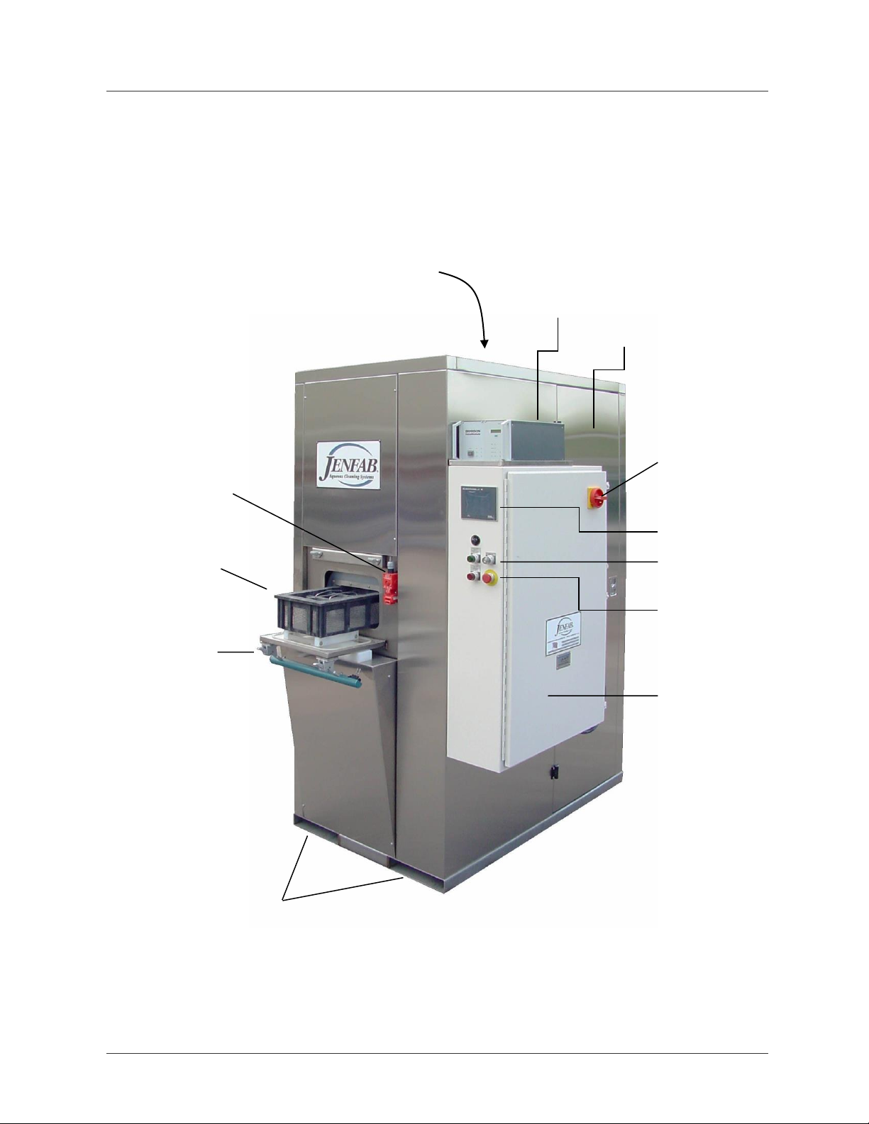
The Lean Clean 360 includes these components (Figure 1):
Basket—holds parts during washing. One basket is provided with the
machine. Several basket designs are available as options.
Loading door—provides access to the washing chamber and seals the
chamber. The machine will not run with the door open. When running, the
door will not open until the cleaning cycle is complete.
Forklift pockets—supports the Lean Clean and enables forklifts to move the
machine.
Ultrasonic generator and transducer (optional)—generates mechanical
sound waves in the washing chamber during washing or rinsing to enhance
the cleaning process. The ultrasonic generator is located on top of the control
panel; the transducer (not shown) is located inside the washing chamber).
Access doors—two side doors and one back door with latching handles
provide access to the piping, tanks, and automated controls for maintenance.
Other panels are removable but require removal of fasteners first.
Main power disconnect—removes all power from system components.
Operator interface—touch screen monitor enables process monitoring,
process control, and program selection and modification.
Controls—power, start, stop and rotation speed control enable operators to
control the Lean Clean.
Electrical control panel—houses electrical and control equipment.
Learning to Use the Lean Clean 360 Cleaning System 13
Figure 1. Lean Clean 360 components
Optional
ultrasonic
generator unit
Access door
Main power
disconnect
Controls
Emergency
stop button
Electrical
control panel
Customer supplies
electrical, compressed air
and water service
Basket holds
parts
Loading door
Forklift pockets
Operator
interface
Door interlock.
Prevents operator from
opening door while
machine is running.

14 Learning to Use the Lean Clean 360 Cleaning System
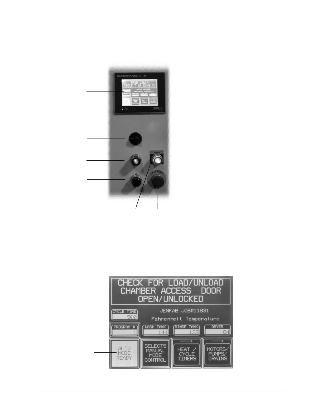
Controls
The controls for the Lean Clean 360 consist of a touch screen monitor, four
control buttons, and a control knob (Figure 2).
Touch screen monitor—the touch screen monitor enables operators to
select a cleaning program to run, monitor process conditions, modify program
parameters, and run the cleaning system manually if desired (Figure 3).
Rotation speed control knob—turning the knob sets the basket rotation
speed from 1 to 6 rpm.
Start button with green indicator light—pressing this button starts the
cleaning cycle. Blinking light indicates system is ready. Steady light indicates
system is running.
Stop button with red indicator light—pressing this button stops the
cleaning cycle.
Power button and yellow indicator light—pressing this button energizes
the system components upon startup or after pressing the emergency stop
button. When you energize the components, the yellow light illuminates.
Emergency Stop Button—pressing this button immediately stops the
cleaning cycle and cuts power to all components except the control power.
Learning to Use the Lean Clean 360 Cleaning System 15
Figure 2. Lean Clean 360 controls
Figure 3. Close up of the touch screen monitor
Power button
with yellow
indicator light
Emergency
stop button
Touch screen
monitor
Rotation speed
control knob
Start button with
green indicator light
Stop button with red
indicator light
The touch screen monitor
enables you to navigate the
process monitoring and
control windows.

16 Learning to Use the Lean Clean 360 Cleaning System
Installation and Setup
Introduction
Complete these steps to prepare the Lean Clean 360 for use:
Unpack the machine
Choose a location
Connect optional equipment
Connect power and utilities
Unpacking the Lean Clean 360
Your Lean Clean 360 should arrive shrink-wrapped and bolted
to a pallet. A heavy cardboard box covers the machine. Screws and strapping
hold the cardboard box in place.
Steps to Unpack the Machine
Remove the strapping and the cover of the cardboard box. Remove the
screws holding the cardboard box to the side of the pallet and remove the
cardboard box. Remove the bolts holding the Lean Clean 360 to the pallet.
Finally, and remove the 2x4 wooden lip on the pallet.
Remove the Lean Clean from the pallet using forklift with a 2,000 pound
lifting capacity. The Lean Clean’s bottom frame includes forklift pockets to
make transportation of the machine convenient and safe.
Remove Documentation and Ancillary Parts
Documentation and some parts are stored in the wash tank for shipping.
After unpacking the machine, open the access panel to the right of the
electrical panel and remove the documentation and parts in the wash tank.
Occasionally documentation ships separately.
Large or sensitive optional equipment such as the optional oil separator or
ultrasonic generator are shipped in separate containers.

Learning to Use the Lean Clean 360 Cleaning System 17
Choosing a Location
Locate the Lean Clean on a smooth level floor capable of holding 2,350
pounds (wet weight) and the weight of any accessory equipment such as the
optional oil separator or drain station.
The Lean Clean footprint is 3 feet by 5 feet, but sufficient room should be left
for operation and maintenance and optional equipment.
If the floor is not level, use shims and a level to level the Lean Clean. A level
installation promotes vibration-free operation, reduces strain on the machine
framework, and promotes proper overflow drainage and liquid level sensing.
The selected location should be clean, dry, and provide efficient work flow
within the manufacturing environment. The location temperature range
should be 55–120°F.
Consider the following location requirements: access to utilities, drains, and
cleaning chemistry supply. Utility requirements include electricity supply,
compressed air, and process water.
Caution—If hot, strong cleaning chemistries contact skin or eyes, bodily injury
can result. To minimize harm in the event of accidental contact with hot cleaning
chemistries, users should locate the Lean Clean in an area with emergency eye
wash and showers, or install an emergency eye wash and showers in the area
where the Lean Clean is installed.
Post Installation Checks
After positioning and leveling the machine, open the process chamber door
and inspect the alignment between the rotating drum support rings and the
flanged rollers. The support rings should be in the flanges. (Rough shipping
and handling can cause the rotating drum to jump out of the flanges.)
Caution—If the rotating drum support rings are not in the flanges and you start
the machine, equipment damage can result. To avoid equipment damage, visually
inspect the support rings on the rotation drum and ensure they are in the flanges.
Ensure there are no foreign objects in the wash tank and rinse tank. Verify
that the chip baskets are in place, the wash and rinse water inline filters are
installed, and that the level and temperature probes
and dryer hose are not damaged.

18 Learning to Use the Lean Clean 360 Cleaning System
Connecting Optional Equipment
JENFAB technicians and engineers install the following optional equipment
at the factory before the Lean Clean is shipped: fresh water spray rinse,
rocking drive, stack light, auto rust inhibitor, external PLC programming port,
and modem.
You must connect these options upon delivery:
Ultrasonic generator—Factory technicians install the transducer at the
factory. You must install the ultrasonic generator flowing the instructions
below:
Oil separator—the oil separator is a stand-alone unit and ships separately.
You must place the separator near the Lean Clean and connect hoses as
described below.
Drain Station—the drain station is a stand-alone unit that ships separately.
You must connect hoses as described below.

Learning to Use the Lean Clean 360 Cleaning System 19
Connecting the Ultrasonic Generator
JENFAB factory technicians install the ultrasonic transducer and all wiring for
the transducer and generator.
To install the ultrasonic generator, unpack it from its box and place it on top
of the control panel facing the front of the machine. Connect the preinstalled
power cable, transducer cable, and interface cable according to the generator
OEM manual (Figure 4).
Figure 4. Typical ultrasonic generator showing connections
on the back panel
Interface connection
Ultrasonic cable
Electric power cable

20 Learning to Use the Lean Clean 360 Cleaning System
Connecting the Drain Station
If your Lean Clean 360 includes the optional 5-gallon drain station, follow
these steps to install it:
1. Locate the following parts included with the drain station:
PVC drain pipe
Flexible air line
2. Locate the drain station near the Lean Clean 360.
3. Using the PVC pipe, connect the main drain from the Lean Clean to
the inlet on the drain station tank (Figure 5).
4. Connect user-supplied flexible hose from outlet of the pump to your
drain or waste collection tank.
Expert Advice—Depending upon the contaminates you are removing with
the Lean Clean 360-1, wash and rinse water disposal may require treatment to
meet national, state, and local environmental regulations. Before connecting the
Lean Clean 360-1 to a drain, ensure the drain is appropriate for the contaminates in
the rinse and wash water.
5. Connect the compressed air line from the Lean Clean to the to air
inlet on the drain station.
6. Connect the high and low level signal cables from the drain station to
the terminals on the Lean Clean control panel.
7. Connect the solenoid control cable from the solenoid to the terminal
on the Lean Clean 360-1 control panel.
This manual suits for next models
1
Table of contents
Popular Ultrasonic Jewelry Cleaner manuals by other brands


Brookstone
Brookstone Ultrasonic Jewelry/DVD Cleaner user manual

POLTI
POLTI Magico AG130 instruction manual

Ribimex
Ribimex Ribitech Cenerill User and maintenance manual

Itouchless
Itouchless AV002A operating manual

Nilfisk-Advance
Nilfisk-Advance MX 103 C quick start guide

Shark
Shark HYDROVAC WD100 Series user manual