manuals.online logo
Brands
  1. Home
  2. •
  3. Brands
  4. •
  5. Jenn-Air
  6. •
  7. Warming Drawer
  8. •
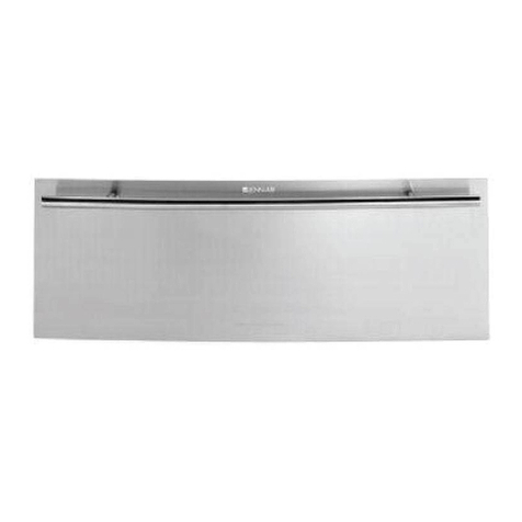
  9. Jenn-Air JWD3030E User guide

Jenn-Air JWD3030E User guide

This manual suits for next models

1

Other Jenn-Air Warming Drawer manuals

Jenn-Air JJD3030IL User manual

Jenn-Air

Jenn-Air JJD3030IL User manual

Jenn-Air JWD2030WX User manual

Jenn-Air

Jenn-Air JWD2030WX User manual

Jenn-Air JJD3024HL User manual

Jenn-Air

Jenn-Air JJD3024HL User manual

Jenn-Air JWD2030W Parts list manual

Jenn-Air

Jenn-Air JWD2030W Parts list manual

Jenn-Air JWD2030WX User manual

Jenn-Air

Jenn-Air JWD2030WX User manual

Jenn-Air JWD6130DDS User manual

Jenn-Air

Jenn-Air JWD6130DDS User manual

Jenn-Air JWD3030EX User manual

Jenn-Air

Jenn-Air JWD3030EX User manual

Jenn-Air W10736617A User manual

Jenn-Air

Jenn-Air W10736617A User manual

Jenn-Air JWD7030CDX Assembly instructions

Jenn-Air

Jenn-Air JWD7030CDX Assembly instructions

Jenn-Air JWD6030CDX User manual

Jenn-Air

Jenn-Air JWD6030CDX User manual

Jenn-Air JWD7130DDS User manual

Jenn-Air

Jenn-Air JWD7130DDS User manual

Jenn-Air JWD2030WS00 User manual

Jenn-Air

Jenn-Air JWD2030WS00 User manual

Jenn-Air JWD7030CDX User manual

Jenn-Air

Jenn-Air JWD7030CDX User manual

Jenn-Air JWD6130DDS User manual

Jenn-Air

Jenn-Air JWD6130DDS User manual

Jenn-Air JWD6030CDX User manual

Jenn-Air

Jenn-Air JWD6030CDX User manual

Jenn-Air JWD2030 User manual

Jenn-Air

Jenn-Air JWD2030 User manual

Jenn-Air W11260097A User manual

Jenn-Air

Jenn-Air W11260097A User manual

Jenn-Air ELECTRIC WARMING DRAWER User manual

Jenn-Air

Jenn-Air ELECTRIC WARMING DRAWER User manual

Popular Warming Drawer manuals by other brands

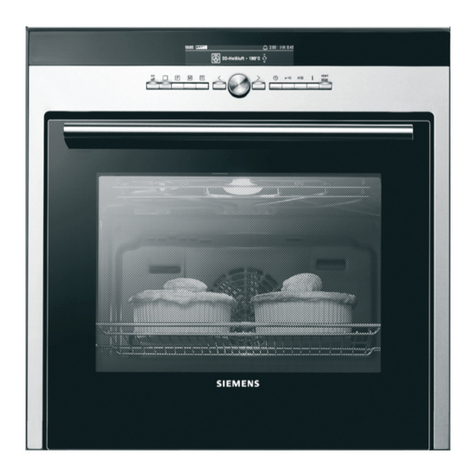
Siemens HW 290 Series instruction manual

Siemens

Siemens HW 290 Series instruction manual

Viking DEWD102SS Quick reference guide

Viking

Viking DEWD102SS Quick reference guide

Miele ESW 6229 Operating and installation instructions

Miele

Miele ESW 6229 Operating and installation instructions

Brandt WD1014X user guide

Brandt

Brandt WD1014X user guide

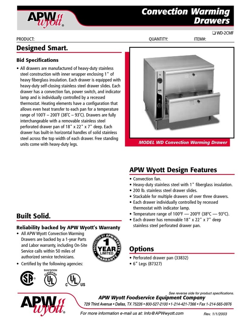
APW Wyott WD-2CMF Specification sheet

APW Wyott

APW Wyott WD-2CMF Specification sheet

KitchenAid KOWT107ESS installation instructions

KitchenAid

KitchenAid KOWT107ESS installation instructions

Hanseatic TCN14J6D-S user manual

Hanseatic

Hanseatic TCN14J6D-S user manual

Cardini WD6299 instruction manual

Cardini

Cardini WD6299 instruction manual

GE Monogram ZTD910SBSS Dimension Guide

GE

GE Monogram ZTD910SBSS Dimension Guide

Dacor IWD24 Planning guide

Dacor

Dacor IWD24 Planning guide

Nordmende WD515IX user manual

Nordmende

Nordmende WD515IX user manual

Electrolux EW30WD55GS Use and care guide

Electrolux

Electrolux EW30WD55GS Use and care guide

Wolf WWD30 troubleshooting guide

Wolf

Wolf WWD30 troubleshooting guide

Fisher & Paykel WB30SDEX1 Quick reference guide

Fisher & Paykel

Fisher & Paykel WB30SDEX1 Quick reference guide

Fisher & Paykel WB60SDTB1-SET Quick reference guide

Fisher & Paykel

Fisher & Paykel WB60SDTB1-SET Quick reference guide

Bosch HWD2720UC installation manual

Bosch

Bosch HWD2720UC installation manual

KitchenAid KEWS105 Use & care guide

KitchenAid

KitchenAid KEWS105 Use & care guide

Baumatic WD01SS user manual

Baumatic

Baumatic WD01SS user manual

manuals.online logo
manuals.online logoBrands
  • About & Mission
  • Contact us
  • Privacy Policy
  • Terms and Conditions

Copyright 2025 Manuals.Online. All Rights Reserved.

JENN-AIR®DETAILED PLANNING DIMENSIONS 1 of 4
IMPORTANT: Dimensional specifications are provided for planning purposes only.
Do not make any cutouts based on this information. Refer to the Installation Guide before
selecting cabinetry, verifying electrical/gas connections, making cutouts or beginning installation.
All Jenn-Air®appliances are appropriately UL, CUL or CSA approved. 8457AdZw615
30"/27" WARMING DRAWERS
JWD3030E – 293⁄4" x 101⁄4" x 26"
JWD3027E – 263⁄4" x 101⁄4" x 26"
FRONT VIEW
TOP VIEW
MODEL # JWD3030E JWD3027E
in cm in cm
AOverall width (max.) 293⁄475.6 263⁄467.9
B
Height to top of handle
Pro-Style®Stainless 91⁄823.2 — —
Euro-Style Stainless 9 23.0 9 23.0
Custom panel (3⁄4"/1.9 cm) * * * *
COverall height (max.) 101⁄426.1 101⁄426.1
DWidth of recessed warming
drawer 281⁄471.8 251⁄464.1
EDepth of recessed warming
drawer 231⁄858.7 231⁄858.7
FDepth with drawer 241⁄261.4 241⁄261.4
G
Depth with handle
Pro-Style®Stainless 267⁄868.1 — —
Euro-Style Stainless 261⁄466.6 261⁄466.6
Custom panel (3⁄4"/1.9 cm) * * * *
H
Depth with drawer fully open
including handle
Pro-Style®Stainless 461⁄8117.1 — —
Euro-Style Stainless 451⁄2115.6 451⁄2115.6
Custom panel (3⁄4"/1.9 cm) ****
*These dimensions to be determined by the custom cabinet maker.
Bottom of Cutout
Back of
Cabinet
A
C
B
I
H
G
F
B
A
D
E
F
G
H
D
E
C
Power Cord Location
Bottom of Cutout
Back of
Cabinet
A
C
B
I
H
G
F
B
A
D
E
F
G
H
D
E
C
Power Cord Location
PRODUCT DIMENSIONS
JENN-AIR®DETAILED PLANNING DIMENSIONS 2 of 4
IMPORTANT: Dimensional specifications are provided for planning purposes only.
Do not make any cutouts based on this information. Refer to the Installation Guide before
selecting cabinetry, verifying electrical/gas connections, making cutouts or beginning installation.
All Jenn-Air®appliances are appropriately UL, CUL or CSA approved. 8457AdZw615
DIMENSIONS AS INSTALLED
SIDE VIEW
MODEL # JWD3030E JWD3027E
in cm in cm
AHeight to top of drawer (max.) 101⁄426.1 101⁄426.1
B
Height to top of handle
Pro-Style®Stainless
85⁄8
21.9
—
—
Euro-Style Stainless 81⁄221.5 81⁄221.5
Custom panel (3⁄4"/1.9 cm) ****
CHeight of drawer extending below cutout 5⁄81.6 5⁄81.6
DHeight of recessed warming drawer 9 23.0 9 23.0
EHeight of warming drawer flange 97⁄825.0 97⁄825.0
F
Depth with drawer fully open including handle
Pro-Style®Stainless
461⁄8
117.1
—
—
Euro-Style Stainless 451⁄2115.6 451⁄2115.6
Custom panel (3⁄4"/1.9 cm) ****
G
Depth with handle
Pro-Style®Stainless
267⁄8
68.1
—
—
Euro-Style Stainless 261⁄466.6 261⁄466.6
Custom panel (3⁄4"/1.9 cm) ****
HDepth with drawer 24 61.0 24 61.0
IDepth of recessed warming drawer 231⁄858.8 231⁄858.8
*These dimensions to be determined by the custom cabinet maker.
30"/27" WARMING DRAWERS
JWD3030E – 293⁄4" x 101⁄4" x 26"
JWD3027E – 263⁄4" x 101⁄4" x 26"
PANEL DIMENSIONS
MODEL # JWD3030E JWD3027E
in cm in cm
AWidth (min.-max.) 29-293⁄473.7-75.6 26-263⁄466.1-67.9
BHeight (min.-max.) 91⁄16-105⁄16 23.0-26.2 91⁄16-105⁄16 23.0-26.2
CHole for indicator light lens (dia.) 5⁄16 0.8 5⁄16 0.8
LOCATION OF INDICATOR LIGHT LENS
Locate lens directly in front of indicator light.
PANEL THICKNESS
Depth of flat or raised panel will vary depending on surrounding cabinetry.
A
Back of Cabinet
F
D
C
D
E
C
A
BC
e
B
e
Bottom of Cutout
Back of
Cabinet
A
C
B
I
H
G
F
B
A
D
E
F
G
H
D
E
C
Power Cord Location
JENN-AIR®DETAILED PLANNING DIMENSIONS 3 of 4
IMPORTANT: Dimensional specifications are provided for planning purposes only.
Do not make any cutouts based on this information. Refer to the Installation Guide before
selecting cabinetry, verifying electrical/gas connections, making cutouts or beginning installation.
All Jenn-Air®appliances are appropriately UL, CUL or CSA approved. 8457AdZw615
A
Back of Cabinet
F
D
C
D
E
C
A
BC
e
B
e
OPENING/CLEARANCE DIMENSIONS
FRONT VIEW
SIDE VIEW
BACK VIEW
30"/27" WARMING DRAWERS
JWD3030E – 293⁄4" x 101⁄4" x 26"
JWD3027E – 263⁄4" x 101⁄4" x 26"
MODEL # JWD3030E JWD3027E
in cm in cm
AWidth of cabinet (min.) 30 76.2 27 68.6
BWidth of cutout 281⁄272.4 251⁄264.8
CHeight between cutouts (min.) 21⁄26.4 21⁄26.4
DHeight of cutout 91⁄823.2 91⁄823.2
EBottom of cutout to floor (recommended) 41⁄410.8 41⁄410.8
Bottom of cutout to floor (min.) 1 2.5 1 2.5
FDepth of cutout (min.) 24 61.0 24 61.0
eRecommended outlet location
ELECTRICAL REQUIREMENTS
120 volt, 60 Hz, AC only, 15-amp fused, electrical circuit is required. A dedicated circuit
is recommended.
If the outlet is on the rear wall behind the warming drawer, it must be recessed and located in
the upper right-hand corner. If outlet is located in an adjacent cabinet, drill a 13⁄8" (3.5 cm)
minimum diameter hole in the side wall or support surface to access the power supply cord.
LOCATION REQUIREMENTS
Support surface must be solid, level and flush with the bottom of the cabinet cutout. The
warming drawer must be leveled before completing installation.
A
Back of Cabinet
F
D
C
D
E
C
A
BC
e
B
e
Bottom of Cutout
Back of
Cabinet
A
C
B
I
H
G
F
B
A
D
E
F
G
H
D
E
C
Power Cord Location
JENN-AIR®DETAILED PLANNING DIMENSIONS 4 of 4
IMPORTANT: Dimensional specifications are provided for planning purposes only.
Do not make any cutouts based on this information. Refer to the Installation Guide before
selecting cabinetry, verifying electrical/gas connections, making cutouts or beginning installation.
All Jenn-Air®appliances are appropriately UL, CUL or CSA approved. 8457AdZw615
e
A
E
F
C
A
BC
B
G
Side Cleat*
15/8" (4.1 cm)
Side Cleat*
1" (2.5 cm)
Side Cleats*
7/8" (2.2 cm)
Platform*
Back of Cabinet
G
D
Bottom of Cutout
Back of
Cabinet
A
C
B
I
H
G
F
B
A
D
E
F
G
H
D
E
C
Power Cord Location
e
A
E
F
C
A
BC
B
G
Side Cleat*
15/8" (4.1 cm)
Side Cleat*
1" (2.5 cm)
Side Cleats*
7/8" (2.2 cm)
Platform*
Back of Cabinet
G
D
e
A
E
F
C
A
BC
B
G
Side Cleat*
15/8" (4.1 cm)
Side Cleat*
1" (2.5 cm)
Side Cleats*
7/8" (2.2 cm)
Platform*
Back of Cabinet
G
D
OPENING/CLEARANCE DIMENSIONS
FRONT VIEW
SIDE VIEW
BACK VIEW
30"/27" WARMING DRAWERS – FLUSH INSTALLATION
JWD3030E – 293⁄4" x 101⁄4" x 241⁄2" (depth without handle)
JWD3027E – 263⁄4" x 101⁄4" x 241⁄2" (depth without handle)
MODEL # JWD3030E JWD3027E
in cm in cm
AWidth of flush inset cutout (min.) 301⁄476.8 271⁄469.2
BWidth of opening (min.) 281⁄471.8 251⁄464.1
CHeight between cutouts (min.) 21⁄26.4 21⁄26.4
DHeight of opening (min.) 91⁄823.2 91⁄823.2
EHeight of flush inset cutout (min.) 103⁄427.3 103⁄427.3
FBottom of cutout to floor (recommended) 81⁄421.0 81⁄421.0
Bottom of cutout to floor (min.) 5 12.7 5 12.7
GDepth of cutout (min.) 253⁄864.5 253⁄864.5
eRecommended outlet location
ELECTRICAL REQUIREMENTS
120 volt, 60 Hz, AC only, 15-amp fused, electrical circuit is required. A dedicated circuit
is recommended.
If the outlet is on the rear wall behind the warming drawer, it must be recessed and located in
the upper right-hand corner. If outlet is located in an adjacent cabinet, drill a 13⁄8" (3.5 cm)
minimum diameter hole in the side wall or support surface to access the power supply cord.
LOCATION REQUIREMENTS
Support surface must be solid, level and flush with the bottom of the cabinet cutout.
The warming drawer must be leveled before completing installation.
FLUSH INSTALLATION REQUIREMENTS
A 253⁄8" (64.5 cm) minimum cutout depth is required.
These dimensions will result in a 1⁄4" (0.6 cm) reveal on all sides of the warming drawer.
The front face of the cleats and platforms will be visible and should be treated as a finished surface.
TOP VIEW
*Cleats and platform must be recessed 1" (2.5 cm) from the front of the cabinet.