Jennov J Series User manual

Monitoring System
(J series)
User Manual
Iphone
Android
JK.2023.029.E
Be sure to read this book before installing or using the surveillance camera.
Keep the book in a safe place so that you can read it whenever necessary.
Please read carefully before use it
U.S Hotline: +13239021978
www.jennov.com
- 01 - - 02 - - 03 - - 04 - - 05 -
- 06 - - 07 - - 08 - - 09 - - 10 - - 11 - - 12 - - 13 - - 14 - - 15 -
- 16 - - 17 - - 18 - - 19 - - 20 - - 21 - - 22 - - 23 - - 24 - - 25 -
- 26 - - 27 - - 28 - - 29 - - 30 - - 31 - - 32 - - 33 - - 34 - - 35 -
- 36 - - 37 - - 38 - - 39 - - 40 - - 41 - - 42 - - 43 - - 44 - - 45 -

Thank-you letter
Dear Customer,
Thank you very much for your trust and purchasing Jennov wireless security camera
system.
Jennov keeps striving for excellence,and its security products are popular all over
the world.Jennov aim at to be top notch brand in surveillance camera filed and
making unremitting efforts to develop more advanced and more convenient products
for users around the world.
Jennov adhere to the principle of customer first and try the best to provide high-qual-
ity products and customized services for our customers.From the procurement of
purchasing raw materials to the rigorous inspection before shipment,the whole
process is under strict control. Moreover, in order to enable Jennov security prod-
ucts to be universal,the latest chip is built in every product,which ensures customers
to get a better user experience.
It is possible for Jennov wireless camera kit to work imperfectly as you expected due
to uncontrollable environmental factors such as distance and obstacles,so please
test the final installation position before set it up,to ensure better use experience.If
you have any problem during your use,please do not leave a review directly to
define the problem,you can contact us via Email,we'd like to fix the problem with
pleasure.
Your suggestion is precious for us to improve the products quality and it's an
opportunity to provide customer services for you.We promise to try our best to
provide the most satisfactory solution for you.
If you are satisfied with our products,please spend one minute in sharing your
experience of this product in the product comments field.Your comment is very
important to other customers who are interested in it or ready to buy it,and also an
important encouragement to force us to keep hard-working.Thank you for your
support!
On behalf of all of Jennov staff,I would like to express my sincere gratitude to you for
your trust and support.If you need assistance,please contact us freely.
Thank you again for your cooperation and support.Wish you healthy and the best
regards to you.Please take care of Jennov in the future!
All staff of Jennov
- 01 - - 02 - - 03 - - 04 - - 05 -
- 06 - - 07 - - 08 - - 09 - - 10 - - 11 - - 12 - - 13 - - 14 - - 15 -
- 16 - - 17 - - 18 - - 19 - - 20 - - 21 - - 22 - - 23 - - 24 - - 25 -
- 26 - - 27 - - 28 - - 29 - - 30 - - 31 - - 32 - - 33 - - 34 - - 35 -
- 36 - - 37 - - 38 - - 39 - - 40 - - 41 - - 42 - - 43 - - 44 - - 45 -

Contents
Chapter 1 Introduction
1.1 Camera Description ..............................................................................01
1.2 Description of NVR video recorder (V80) .............................................02
1.3 Description of 12-inch NVR monitor (V16)............................................03
1.4 Description of 10-inch NVR monitor( V18 ) ..........................................04
1.5 How to install the hard disk...................................................................05
1.6 Connection Instruction...........................................................................07
1.7 How to install the wireless cameras .....................................................08
1.8 Set the flip function of the dome camera screen....................................09
Chapter 2 Features Setting
2.1 NVR login ..............................................................................................10
2.2. Basic Button Introduction ....................................................................11
2.3 Change the system language of the NVR ............................................12
2.4 Adjust the system time and date of the NVR ........................................13
2.5 Set up 24/7 hours recording..................................................................13
2.6 Set up 24/7 hours motion detection video recording.............................14
2.7 How to format the HDD.........................................................................15
2.8 How to playback local video files on TV................................................16
2.9 Hard disk overwrite function..................................................................16
2.10 Backup video data...............................................................................17
2.11 Strengthen the camera signal via Repeater function..........................18
2.12 Camera upgrade and NVR version information..................................20
Chapter 3 Alarm Setting
3.1 Alarm setting instructions......................................................................21
3.2 Set the motion detection area ..............................................................21
3.3 How to erase the exclamation mark......................................................22
3.4 Email alarm of motion detection ...........................................................23
- 01 - - 02 - - 03 - - 04 - - 05 -
- 06 - - 07 - - 08 - - 09 - - 10 - - 11 - - 12 - - 13 - - 14 - - 15 -
- 16 - - 17 - - 18 - - 19 - - 20 - - 21 - - 22 - - 23 - - 24 - - 25 -
- 26 - - 27 - - 28 - - 29 - - 30 - - 31 - - 32 - - 33 - - 34 - - 35 -
- 36 - - 37 - - 38 - - 39 - - 40 - - 41 - - 42 - - 43 - - 44 - - 45 -

Chapter 4 PC/Smartphone Operation Introduction
4.1 Smartphone usage guide.......................................................................31
4.2 Settings of pushing mobile phone alarm messages..............................32
4.3 How to play back detect video with computer........................................32
Chapter 5 FAQ
5.1 Add a new camera to NVR ...................................................................35
5.2 Precautions when rematching codes or replacing cameras..................36
5.3 What if you forget NVR system password ............................................37
5.4 The NVR monitor does not show pictures.............................................38
5.5 The camera does not work and no picture shows.................................39
5.6 Solution to [HDD hard disk cannot be found]........................................39
5.7 What's the solution when NVR shows offline........................................40
5.8 What is the function of the network cable..............................................41
- 01 - - 02 - - 03 - - 04 - - 05 -
- 06 - - 07 - - 08 - - 09 - - 10 - - 11 - - 12 - - 13 - - 14 - - 15 -
- 16 - - 17 - - 18 - - 19 - - 20 - - 21 - - 22 - - 23 - - 24 - - 25 -
- 26 - - 27 - - 28 - - 29 - - 30 - - 31 - - 32 - - 33 - - 34 - - 35 -
- 36 - - 37 - - 38 - - 39 - - 40 - - 41 - - 42 - - 43 - - 44 - - 45 -

Preface
1.1 Camera Description
1) This manual instruction is for reference only. As the equipment is updated, it may be
different from what is described in this pamphlet.
2) After receiving the products, please check whether all accessories are in the package.
3) Before installation, please turn on the power to check whether the camera picture appears
on the NVR(monitor).
4) The NVR has built-in wifi receiver. In order to ensure the IP camera can receive the NVR
signal perfectly, please install the camera in the scope that wifi signal can arrive. (please test
whether the NVR wifi signal is reachable or not in advance).
5) All the cameras have been matched with NVR, and the NVR can be viewed and operated
immediately after being powered on.
6) If you want to realize remote viewing on your smartphone,please connect the NVR to your
router by network cable.
Camera support bracket
2.4dbi antenna
IP68 waterproof metal case
infrared lights
Infrared sensor
3.6MM lens
RJ45 port
Network indicator
Power supply port
install on the wall install on the ceiling
Chapter 1 Introduction
- 01 - - 02 - - 03 - - 04 - - 05 -
- 06 - - 07 - - 08 - - 09 - - 10 - - 11 - - 12 - - 13 - - 14 - - 15 -
- 16 - - 17 - - 18 - - 19 - - 20 - - 21 - - 22 - - 23 - - 24 - - 25 -
- 26 - - 27 - - 28 - - 29 - - 30 - - 31 - - 32 - - 33 - - 34 - - 35 -
- 36 - - 37 - - 38 - - 39 - - 40 - - 41 - - 42 - - 43 - - 44 - - 45 -

1.2 Description of NVR video recorder (V80)
1) VGA port: Connect NVR and monitor with VGA cable(package does not include VGA cable).
2) HDMI port: Connect NVR and TV/monitor with HDMI cable.
3) LAN port:
A. Connecting the NVR and router with a network cable if you want to view remotely.
B. When you want to add a new camera to the NVR recorder,or when camera can't connect
to the NVR via wifi,you will need to connect the NVR and camera with a network cable.
4) USB port: Operated with a USB mouse,used to save video files with a USB flash drive,
used for system upgrade.
5) Power supply port: 12V/2A DC power adapter.
6) Antenna:Transmit wifi signal from NVR.
7) Power indicator: Light will turn to red when the NVR is powered.
8) HDD indicator:Light will turn to green when HDD works normally.
5dbi antenna
Power supply port
USB port
LAN port
HDMI port
VGA port
5dbi antenna
Hard drive indicator
Running indicator
Power indicator
Note:
1. The number of cameras supported to be added to NVR is related to the number of NVR
channels(you can find the number of channels supported by NVR in "Video Management").
2. Laptop can't be used as a display to present real time picture,but you can view real-time
picture and playback local videos on TV and PC.
- 01 - - 02 - - 03 - - 04 - - 05 -
- 06 - - 07 - - 08 - - 09 - - 10 - - 11 - - 12 - - 13 - - 14 - - 15 -
- 16 - - 17 - - 18 - - 19 - - 20 - - 21 - - 22 - - 23 - - 24 - - 25 -
- 26 - - 27 - - 28 - - 29 - - 30 - - 31 - - 32 - - 33 - - 34 - - 35 -
- 36 - - 37 - - 38 - - 39 - - 40 - - 41 - - 42 - - 43 - - 44 - - 45 -

1.3 Description of 12-inch NVR monitor (V16)
1) Power indicator: Light will turn to red when the NVR is powered on.
2) HDD indicator:Light will turn to green when HDD works normally.
3) Switch button:Press the button to turn on/off the screen.
4) HDMI port: Connect NVR and TV/monitor with HDMI cable.
5) LAN port:
A. Connecting the NVR and router with a network cable if you want to view remotely.
B. When you want to add a new camera to the NVR recorder,or when camera can't connect
to the NVR via wifi,you will need to connect the NVR and camera with a network cable.
6) USB port: Operated with a USB mouse,used to save video files with a USB flash drive,
used for system upgrade.
7) Power supply port: 12V/2A DC power adapter.
8) Antenna:Transmit wifi signal from NVR.
9) Monitor base stand:90 degree adjustment.
Hard drive installation place
Monitor base stand
USB port
LAN port
HDMI port
5dbi antenna
Power supply port
Switch button
Hard drive indicator
Power indicator
5dbi antenna
Note:
Due to system updates, the above buttons may be renamed.
1.12-inch NVR monitor only supports 3.5-inch hard drives.
2. Please note that it is not compatible with external hard drives.
- 01 - - 02 - - 03 - - 04 - - 05 -
- 06 - - 07 - - 08 - - 09 - - 10 - - 11 - - 12 - - 13 - - 14 - - 15 -
- 16 - - 17 - - 18 - - 19 - - 20 - - 21 - - 22 - - 23 - - 24 - - 25 -
- 26 - - 27 - - 28 - - 29 - - 30 - - 31 - - 32 - - 33 - - 34 - - 35 -
- 36 - - 37 - - 38 - - 39 - - 40 - - 41 - - 42 - - 43 - - 44 - - 45 -

1.4 Description of 10-inch NVR monitor (V18)
1) Power indicator: Light will turn to red when the NVR is powered on
2) Switch button: Press the button to turn on/off the screen.
3) Power supply port: 12V/2A DC power adapter .
4) USB port: Operated with a USB mouse,used to save video files with a USB flash drive,used for
system upgrade.
5) HDMI port: Connect NVR and TV/monitor with HDMI cable.
6) LAN port:
A. Connecting the NVR and router with a network cable if you want to view remotely.
B. When you want to add a new camera to the NVR recorder,or when camera can't connect to the
NVR via wifi,you will need to connect the NVR and camera with a network cable.
7) Reset button: Press the button for at least 15 seconds to reset the NVR.
8) SD card slot: Supports SD card up to 256G.
9) Antenna:Transmit wifi signal from NVR.
10) Monitor base stand: 40 degree adjustment.
11) Mounting holes: NVR can be mounted on the wall.
Switch button
Reset button
HDMI port
LAN port
Power supply port
Monitor stand
Mounting holes
2.5 inch hard disk
USB port
SD card slot
5dBi antenna
Power indicator
Note:
1. The 10-inch NVR monitor only supports 2.5-inch HDDs, not SSDs.
2. Please note that it is not compatible with external hard drives.
- 01 - - 02 - - 03 - - 04 - - 05 -
- 06 - - 07 - - 08 - - 09 - - 10 - - 11 - - 12 - - 13 - - 14 - - 15 -
- 16 - - 17 - - 18 - - 19 - - 20 - - 21 - - 22 - - 23 - - 24 - - 25 -
- 26 - - 27 - - 28 - - 29 - - 30 - - 31 - - 32 - - 33 - - 34 - - 35 -
- 36 - - 37 - - 38 - - 39 - - 40 - - 41 - - 42 - - 43 - - 44 - - 45 -

1.5 How to install the hard disk
Please turn off the recorder when installing the hard disk.
About the type of black box NVR(V80)
About the type with 12’’ NVR monitor(V16)
3.Align the HDD to the four holes of back
panel, and then fix the HDD with screws.
2. Connect HDD to the Device using data
cable and power cable.
1.Unscrew four fixing screws of the
cover and remove the cover.
4.Put back and fix the cover with the
screw in Step 1 to finish the installation.
4.Put back and fix the cover with the
screw in Step 1 to finish the installation.
3.Turn over the Device, and align the HDD to
the four holes of bottom panel, and then fix
the HDD with screws in the screw package.
2. Connect HDD to the Device using data
cable and power cable.
1.Unscrew four fixing screws of the
cover and remove the cover.
- 01 - - 02 - - 03 - - 04 - - 05 -
- 06 - - 07 - - 08 - - 09 - - 10 - - 11 - - 12 - - 13 - - 14 - - 15 -
- 16 - - 17 - - 18 - - 19 - - 20 - - 21 - - 22 - - 23 - - 24 - - 25 -
- 26 - - 27 - - 28 - - 29 - - 30 - - 31 - - 32 - - 33 - - 34 - - 35 -
- 36 - - 37 - - 38 - - 39 - - 40 - - 41 - - 42 - - 43 - - 44 - - 45 -

About the type with 10 " NVR monitor(V16)
Please turn off the recorder when installing the hard disk.
4.Push the cover and fit it into the main body.
3.Connect HDD to the Device using data
cable and power cable.
2.Align the HDD to the four holes of cover,
and then fix the HDD with screws.
1.Remove the cover.
- 01 - - 02 - - 03 - - 04 - - 05 -
- 06 - - 07 - - 08 - - 09 - - 10 - - 11 - - 12 - - 13 - - 14 - - 15 -
- 16 - - 17 - - 18 - - 19 - - 20 - - 21 - - 22 - - 23 - - 24 - - 25 -
- 26 - - 27 - - 28 - - 29 - - 30 - - 31 - - 32 - - 33 - - 34 - - 35 -
- 36 - - 37 - - 38 - - 39 - - 40 - - 41 - - 42 - - 43 - - 44 - - 45 -

2) Connection Instruction of NVR Embedded Display Model
Step 1: Screw the antenna to the camera.
Step 2: Connect the NVR to the TV/monitor with a VGA / HDMI cable.
Step 3: Insert the mouse.
Step 4: Power on the camera and NVR(you can watch the camera real-time picture after
tens of seconds, support local viewing, playback, etc.) (NVR power supply adapter is
12V/2A, camera power adapter is 12V/1A).
Step 5: Insert the network cable into the LAN port of the NVR and router(this step is
necessary for remote viewing on the mobile phone/PC).
Step 1: Screw the antenna to the camera.
Step 2: Connect the monitor to the TV with a VGA /
HDMI cable,if you want the pictures presented on a
broader screen.
Step 3: Insert the mouse.
Step 4: Power on the camera and NVR(you can
watch the camera real-time picture after tens of
seconds, support local viewing, playback, etc.)
(NVR power supply adapter is 12V/2A, camera
power adapter is 12V/1A).
Step 5: Insert the network cable into the LAN port
of the NVR and router(this step is necessary for
remote viewing on the mobile phone/PC).
1.6 Connection Instruction
1) Connection Instruction of Black NVR Video Recorder
Back of 12 inch monitor
Router
Front of 12 inch monitor
2
1
4
3
- 01 - - 02 - - 03 - - 04 - - 05 -
- 06 - - 07 - - 08 - - 09 - - 10 - - 11 - - 12 - - 13 - - 14 - - 15 -
- 16 - - 17 - - 18 - - 19 - - 20 - - 21 - - 22 - - 23 - - 24 - - 25 -
- 26 - - 27 - - 28 - - 29 - - 30 - - 31 - - 32 - - 33 - - 34 - - 35 -
- 36 - - 37 - - 38 - - 39 - - 40 - - 41 - - 42 - - 43 - - 44 - - 45 -

Camera field of view
Motion detection range
Up to 30ft ( 10m )
7-10ft
(2-3m)
*Try to avoid obstacles between the camera and NVR, so that the camera can receive the NVR signal
well.
(1) If there are no obstacles, the camera can be installed about 40m away from the NVR.
(2) If there is a wall between the camera and NVR, reduce the distance to 20m.
(3) If there are two walls, reduce the distance to 10m.
*The above wireless LAN range may vary depending on the environment, please check whether the
camera can work normally before installing the camera, and then install it within the effective range of
the NVR wireless LAN.
*For better night vision effect, please avoid camera lens facing the light.
*Try to install the video recorder and camera antenna in the same row and in the same direction.
*Install the NVR as high as possible so that the wifi transmission is not hindered by the crowd.
1.7 How to install the wireless cameras
It is recommended to install the camera 2-3 meters above the ground, so that the
moving object range of the camera moving object sensor can be maximized.
Since the camera receives wifi from the NVR, please install the camera within the
effective wifi signal distance as much as possible.
Installation Precautions:
- 01 - - 02 - - 03 - - 04 - - 05 -
- 06 - - 07 - - 08 - - 09 - - 10 - - 11 - - 12 - - 13 - - 14 - - 15 -
- 16 - - 17 - - 18 - - 19 - - 20 - - 21 - - 22 - - 23 - - 24 - - 25 -
- 26 - - 27 - - 28 - - 29 - - 30 - - 31 - - 32 - - 33 - - 34 - - 35 -
- 36 - - 37 - - 38 - - 39 - - 40 - - 41 - - 42 - - 43 - - 44 - - 45 -

Ok Cancel
IP Address
0/0
Channel Device Name IP Address Status
5523-W
5523-W
5523-W
5523-W
172 . 20 . 14 . 30
172 . 20 . 14 . 31
172 . 20 . 14 . 32
172 . 20 . 14 . 33
1
2
3
4
5
6
7
8
ID Device Name
N1
Por Protocol
Search
Match Code
Add One
Modify IP
Advanced
Protocol
Delete
Delete All
Manual Edit
Channel Setup
Wireless Setup
Repeater
Connect Success
Connect Success
Connect Success
Connect Success
No Video Source
No Video Source
No Video Source
No Video Source
As shown below:
Split Screen
Video Manage
System Setup
Video Playback
Video Backup
Setup Wizard
Fast Network
Repeater
Wireless Add
Exit System
+
+
+
I
1
2
Figure 1
Figure 2
Figure 3 Figure 4
Before flipping the image
1.8 Set the flip function of the dome camera screen on the NVR interface
When your dome camera is connected to the NVR, if the picture is flipped, we need to adjust the
picture of the camera according to the following steps.
Right-click the screen to open the main menu - video management - select device - edit
channel - image flip, click OK. It can also be copied to other channels at the same time.
Then adjust the viewing angle up and down during installation.
Apply Ok Cancel
General Setup
Time Setup
HDD Setup
Error Setup
Language
Display Resolution
Auto Logout
Key Buzzer
Keypad Type
Remote ID
Auto Switch
OSD Alpha
Volume
Show Cloud ID When Preview
Show Time When Preview
General Setup Record Setup Network Setup Channel Setup System Admin
Enable
Enable
English
1280x1024
Disable
Enable
Type1
0
5 seconds x1 View x4 View
Enable
.
-
-
+
+
Edit Channel Connection Parameters
Channel
Protocol
Port
MAC Address
1
N1
80
9CAD-A987-451D
Reboot
Image Rollover
ID
Enable
IPaddress
Password
Cancel
Took
Copy
Username
Preview Stratage
admin
3576755952
172. 20. 14. 31
- 01 - - 02 - - 03 - - 04 - - 05 -
- 06 - - 07 - - 08 - - 09 - - 10 - - 11 - - 12 - - 13 - - 14 - - 15 -
- 16 - - 17 - - 18 - - 19 - - 20 - - 21 - - 22 - - 23 - - 24 - - 25 -
- 26 - - 27 - - 28 - - 29 - - 30 - - 31 - - 32 - - 33 - - 34 - - 35 -
- 36 - - 37 - - 38 - - 39 - - 40 - - 41 - - 42 - - 43 - - 44 - - 45 -

(2) Set NVR password
If you want to change the password,please follow the steps:
right click your mouse enter System Setup>System Admin>User>Set Password.
You can enter a new username and password.
Note: The new password must less than 12 characters.Please do not use special
characters,such as #,$,%,&.
Username
admin
Password
Remember Password
Cancelok
Ok Cancel
1
2
Add User
Delete User
ID
1
2
3
4
5
6
7
8
9
10
11
12
admin Yes
Super userUserName
General Setup Record Setup Network Setup Channel Setup System Admin
System Version
System Log
User
System Upgrade
Sys Maintenance
Factory Setting
Ok Cancel
Username
New password
Repeated
Password length ( up to 12 characters )
admin
2.1 NVR login
(1) Method of NVR login
The username is admin,and no password by default(please keep password to be blank),then
clicked “OK” to enter the NVR system directly.
Chapter 2 Features Setting
- 01 - - 02 - - 03 - - 04 - - 05 -
- 06 - - 07 - - 08 - - 09 - - 10 - - 11 - - 12 - - 13 - - 14 - - 15 -
- 16 - - 17 - - 18 - - 19 - - 20 - - 21 - - 22 - - 23 - - 24 - - 25 -
- 26 - - 27 - - 28 - - 29 - - 30 - - 31 - - 32 - - 33 - - 34 - - 35 -
- 36 - - 37 - - 38 - - 39 - - 40 - - 41 - - 42 - - 43 - - 44 - - 45 -

Click on the monitoring screen, and several icons such as sound switch, electronic zoom, color
adjustment, PTZ setting (requires device support) will pop up at the bottom of the screen.
(2) Volume: If the recording function is installed on the device, after turning on the sound mark, you
can hear the live sound on the monitor.
If the machine you are using has a recording function, you can adjust the sound according to the
following steps. If there is no recording function, please ignore this step.
Split Screen
Video Manage
System Setup
Video Playback
Video Backup
Setup Wizard
Fast Network
Repeater
Wireless Add
Exit System
+
+
I
1
1
2
3
4
Apply Ok Cancel
General Setup
Time Setup
HDD Setup
Error Setup
Language
Display Resolution
Auto Logout
Key Buzzer
Keypad Type
Remote ID
Auto Switch
OSD Alpha
Volume
Show Cloud ID When Preview
Show Time When Preview
General Setup Record Setup Network Setup Channel Setup System Admin
Enable
Enable
English
1280x1024
Disable
Enable
Type1
0
5 seconds x1 View x4 View
Enable
.
-
-
+
+
Edit Channel Connection Parameters
(1) Split Screen Setting
Click the right mouse button-Main Menu-Split
Screen
Note: You can select 1/4/6/8 screen for the monitor
screen, but you cannot set 2 screens.
X1 View
X4 View
X6 View
X8 View
1
2
3
4
5
6
7
8
Split Screen
Video Manage
System Setup
Video Playback
Video Backup
Setup Wizard
Fast Network
Repeater
Wireless Add
Exit System
+
+
I
2.2 Basic Button Introduction
- 01 - - 02 - - 03 - - 04 - - 05 -
- 06 - - 07 - - 08 - - 09 - - 10 - - 11 - - 12 - - 13 - - 14 - - 15 -
- 16 - - 17 - - 18 - - 19 - - 20 - - 21 - - 22 - - 23 - - 24 - - 25 -
- 26 - - 27 - - 28 - - 29 - - 30 - - 31 - - 32 - - 33 - - 34 - - 35 -
- 36 - - 37 - - 38 - - 39 - - 40 - - 41 - - 42 - - 43 - - 44 - - 45 -

2.3 Steps to change the system language of the NVR recorder
Please right click your mouse and enter System Setup>General Setup>Language,
choose your language and click OK.
Apply Ok Cancel
2
General Setup
Time Setup
HDD Setup
Error Setup
Language
Display Resolution
Auto Logout
Key Buzzer
Keypad Type
Remote ID
Auto Switch
OSD Alpha
Volume
Show Cloud ID When Preview
Show Time When Preview
General Setup Record Setup Network Setup Channel Setup System Admin
1
Enable
Enable
English
English
x1 View x4 View
Enable
.
-
-
+
+
OK Cancel
Hue
Brightness
Saturation
Contrast
Sharpness
Ircut mode
Update Success
32
32
32
32
32
-
+
-
+
Infrared mode
daylight
night
full color mode
smart mode
Default
Bright
Soft
smart mode
Exit Tour Start Speed
Preset
Store
Goto
Zoom
Focus
Iris
(5) PTZ control: You can adjust the movement up, down, left and right using the arrow buttons.
Note: This feature depends on the installed camera model.
(3) Zoom in: You can achieve digital zoom by clicking "+" with the mouse. Check the position of the mouse
arrow, scroll the mouse and zoom in on the position you want to see.
Please note: The electronic zoom is magnified based on the original screen, not the surveillance
screen clearly magnified. The higher the zoom factor, the blurry the screen.
(4) Light & Color: You can adjust the brightness of the screen and the night vision mode of the
camera.
- 01 - - 02 - - 03 - - 04 - - 05 -
- 06 - - 07 - - 08 - - 09 - - 10 - - 11 - - 12 - - 13 - - 14 - - 15 -
- 16 - - 17 - - 18 - - 19 - - 20 - - 21 - - 22 - - 23 - - 24 - - 25 -
- 26 - - 27 - - 28 - - 29 - - 30 - - 31 - - 32 - - 33 - - 34 - - 35 -
- 36 - - 37 - - 38 - - 39 - - 40 - - 41 - - 42 - - 43 - - 44 - - 45 -

2.4 How to adjust the system time and date of the NVR recorder?
1) Adjust system time and date automatically
Connecting the NVR and router with a network cable to ensure the NVR system is online.
Right click the mouse and select System Setup> General Setup> Time Setup,if you want
to synchronize your local time and date,please enable “Sync Time” ,finally click “OK” .
2) Adjust system time and date manually
Right click the mouse and select System Setup>General Setup>Time Setup,please cancel “Sync Time” .
Then set up “System Date” and “System Time” manually,finally click “OK” .
Apply Ok Cancel
2
General Setup
Time Setup
HDD Setup
Error Setup
Date Format
Sync Time
Time Zone
General Setup Record Setup Network Setup Channel Setup System Admin
1
Advanced Summer Time
YYYY/MM/DD
Time Format
Enable
+08:00
.
12h 24h
2021/09/14 10:28:31
2.5 Steps to set up 24/7 hours recording
1) Click "System Setup" in the main menu,then select the "Record Setup",enter “Record Plan” .
2) Choose “Time” then click “Select All” , finally click “Apply” & “OK” .
Settings for 24/7 continuous recording is completed.
Note:After completing the Setting,the red square indicates the system is under 24/7 hours recording.
Copy To
Channel
Record Plan
Time Motion Alarm
Mo
Tu
We
Th
Fr
Sa
Su
210 3 4 5 6 7 8 9 10 11 12 13 14 15 16 17 18 19 20 21 22 23
1
General Setup Record Setup Network Setup Channel Setup System Admin
Select All Reset Apply OKCancel
Copy To
Channel
Record Plan
Time Motion Alarm
Mo
Tu
We
Th
Fr
Sa
Su
210 3 4 5 6 7 8 9 10 11 12 13 14 15 16 17 18 19 20 21 22 23
1
General Setup Record Setup Network Setup Channel Setup System Admin
Select All Reset Apply OKCancel
- 01 - - 02 - - 03 - - 04 - - 05 -
- 06 - - 07 - - 08 - - 09 - - 10 - - 11 - - 12 - - 13 - - 14 - - 15 -
- 16 - - 17 - - 18 - - 19 - - 20 - - 21 - - 22 - - 23 - - 24 - - 25 -
- 26 - - 27 - - 28 - - 29 - - 30 - - 31 - - 32 - - 33 - - 34 - - 35 -
- 36 - - 37 - - 38 - - 39 - - 40 - - 41 - - 42 - - 43 - - 44 - - 45 -

2.6 Steps to set up 24/7 hours motion detection video recording
1) Click "System Setup" in the main menu,and select "Record Setup",then you will enter “Record Plan” .
2) Choose “Motion” and click “Reset” , then click “Select All” finally click “Apply” and “OK” to complete the
motion detection recording settings.
Note:After completing the settings,the green square indicates the system is under motion detection
recording.
Special instructions for recording settings:
A.Clicking “Time” and selecting all the time period,that's 24-hour recording.If you select specific
time period,then the system will record during the time you've set up.Clicking “Motion”
and select time period,that's motion detection recording.
B. For this wireless camera system,you can set up both 24 -hour recording and motion
detection recording at the same time,or only record during the time period you've set up when
motion happens.
Copy To
Channel
Record Plan
Time Motion Alarm
Mo
Tu
We
Th
Fr
Sa
Su
210 3 4 5 6 7 8 9 10 11 12 13 14 15 16 17 18 19 20 21 22 23
1
General Setup Record Setup Network Setup Channel Setup System Admin
Select All Reset Apply OKCancel
Copy To
Channel
Record Plan
Time Motion Alarm
Mo
Tu
We
Th
Fr
Sa
Su
210 3 4 5 6 7 8 9 10 11 12 13 14 15 16 17 18 19 20 21 22 23
1
General Setup Record Setup Network Setup Channel Setup System Admin
Select All Reset Apply OKCancel
Copy To
Channel
Record Plan
Time Motion Alarm
Mo
Tu
We
Th
Fr
Sa
Su
210 3 4 5 6 7 8 9 10 11 12 13 14 15 16 17 18 19 20 21 22 23
1
General Setup Record Setup Network Setup Channel Setup System Admin
Select All Reset Apply OKCancel
- 01 - - 02 - - 03 - - 04 - - 05 -
- 06 - - 07 - - 08 - - 09 - - 10 - - 11 - - 12 - - 13 - - 14 - - 15 -
- 16 - - 17 - - 18 - - 19 - - 20 - - 21 - - 22 - - 23 - - 24 - - 25 -
- 26 - - 27 - - 28 - - 29 - - 30 - - 31 - - 32 - - 33 - - 34 - - 35 -
- 36 - - 37 - - 38 - - 39 - - 40 - - 41 - - 42 - - 43 - - 44 - - 45 -

You need to format the HDD before using it.
Also, if there is something wrong with the hard disk (such as not being able to
record), the HDD will be formatted. Please try it.
1) Black Box NVR (V80)
2) NVR Nonitor (V16/V18)
2.7 How to format the HDD
General Setup Record Setup Network Setup Channel Setup System Admin
Ok Cancel
Apply
Formatted
General Setup
Time Setup
Storage Manage
Error Setup
Storage Device
Model
Status
Total Size
Used Size
Free Size
Note : TF Card needs to meet the writing speed of 10MB/s,
otherwise it may cause recording faill
TFCARD
SL64G
Formatted
256.0GB
0.5GB
237.8GB
1
2
Note:
1. Up to 4TB hard drive can be used.
2. SD card recording is compatible with NVR and can support up to 256G SD card.
3. Please note that only one of the storage methods can be selected, and the sd card and hard disk
cannot be used at the same time.
General Setup Record Setup Network Setup Channel Setup System Admin
Ok Cancel
Apply
Overwrite
Total Size
Used Size
Free Size
465. 8 GB
20. 0 GB
445. 8 GB
4. 3%
95. 7%
ID Mode Capacity Used Status Format
1 WDC WD5000AADS-0 465.8 GB 20.0 GB Formatted
General Setup
Time Setup
HDD Setup
Error Setup
Formatted
1
2
- 01 - - 02 - - 03 - - 04 - - 05 -
- 06 - - 07 - - 08 - - 09 - - 10 - - 11 - - 12 - - 13 - - 14 - - 15 -
- 16 - - 17 - - 18 - - 19 - - 20 - - 21 - - 22 - - 23 - - 24 - - 25 -
- 26 - - 27 - - 28 - - 29 - - 30 - - 31 - - 32 - - 33 - - 34 - - 35 -
- 36 - - 37 - - 38 - - 39 - - 40 - - 41 - - 42 - - 43 - - 44 - - 45 -
Table of contents
Popular Measuring Instrument manuals by other brands
Topcon
Topcon RL-H1Sa instruction manual
Ludlum Measurements
Ludlum Measurements 177 manual

Würth
Würth 0964 764 009 Translation of the original operating instructions

Zhejiang Uniview Technologies
Zhejiang Uniview Technologies B3223P30 Release notes

Wintriss
Wintriss AutoSet PAC 120 VAC user manual
Rigol
Rigol DSA1000 Series Accessories User Guide

Skil
Skil 2100DAF Operating/safety instructions
HiTec Systems
HiTec Systems AtmoCheck operating manual
Garmin
Garmin LIDAR-Lite v1 Silver Label operating manual
Han Seung
Han Seung HTS-CT10 Operation manual
SPI
SPI 18-010-9 Operation manual
PCB Piezotronics
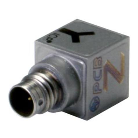
PCB Piezotronics 356A43 Installation and operating manual
