Jensen CD515K Instruction Manual

How to Enjoy Your CD515K AM/FM
Stereo Receiver/CD Player with Optional
CD Changer Control and Detachable
Flip-Over Security Panel
®
CD515K Features
Technical Assistance
For technical assistance with the operation of the CD515K,
call 1-800-323-0221.
Operation
Welcome!
What you're holding in your hands is no ordinary owner's
manual. We've tried to make the instructions in this owner's
manual clear and easy to follow. If you take a few minutes to
look through it, you'll learn how to use all of the features on
your new Jensen car stereo for maximum enjoyment.
For your Jensen stereo to work right, it must be installed
correctly. The enclosed installation manual will show you how
to install your new stereo like a pro. It's a good idea to read
all of these instructions before you begin the installation.
Most installations are straightforward and can be handled by
a do-it-yourselfer with the right tools, patience, and the ability
to follow instructions. But, do-it-yourself installation isn't for
everyone. If you still don't feel confident after reading this
book, consider turning the installation job over to someone
better suited to it.
Warranty Service
If your Jensen stereo should ever require service, you will
need to have the original dated receipt. If you ever need to
return the unit for any reason, always include the receipt with
the product.
Basic Operation ......................... 2
On/Off ............................................ 2
Select Function .............................. 2
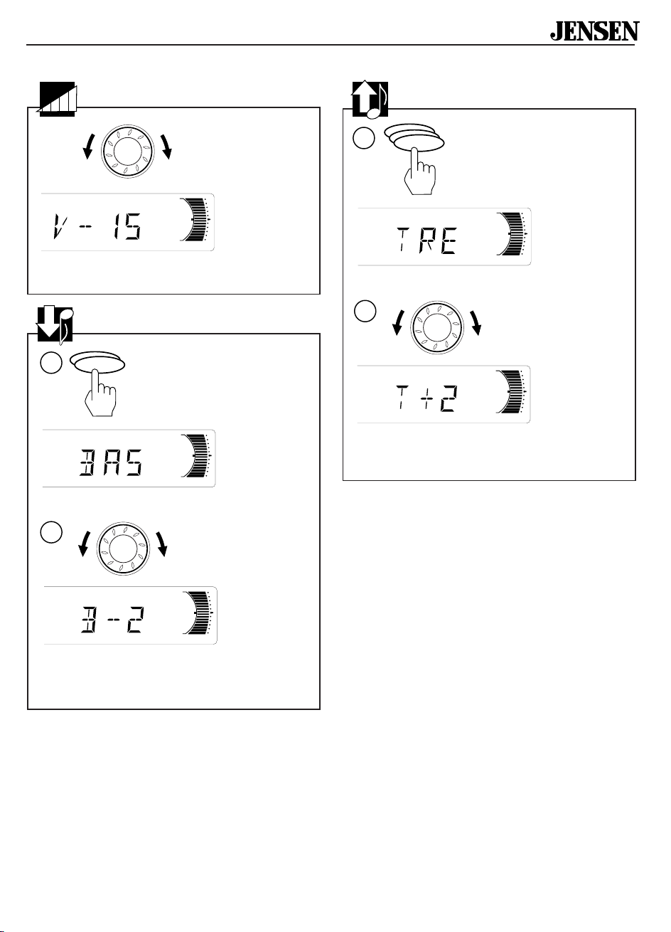
Volume ........................................... 3
Bass ............................................... 3
Treble ............................................. 3
Balance .......................................... 4
Fader.............................................. 4
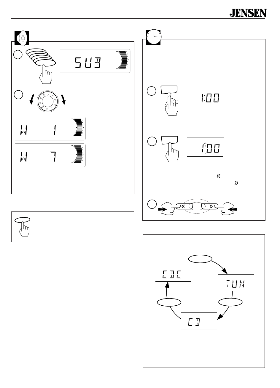
Sub (subwoofer) ............................ 5
Loudness ....................................... 5
View/Set the Clock ......................... 5
Mode .............................................. 5
Radio Operation ......................... 6
Radio Mode.................................... 6
Select a Band ................................ 6
Select a Station .............................. 6
Stereo Reception ........................... 6
Preset Stations .............................. 7
Automatically Store Stations .......... 7
Scan Stored Stations
(Preset Scan) ................................. 7
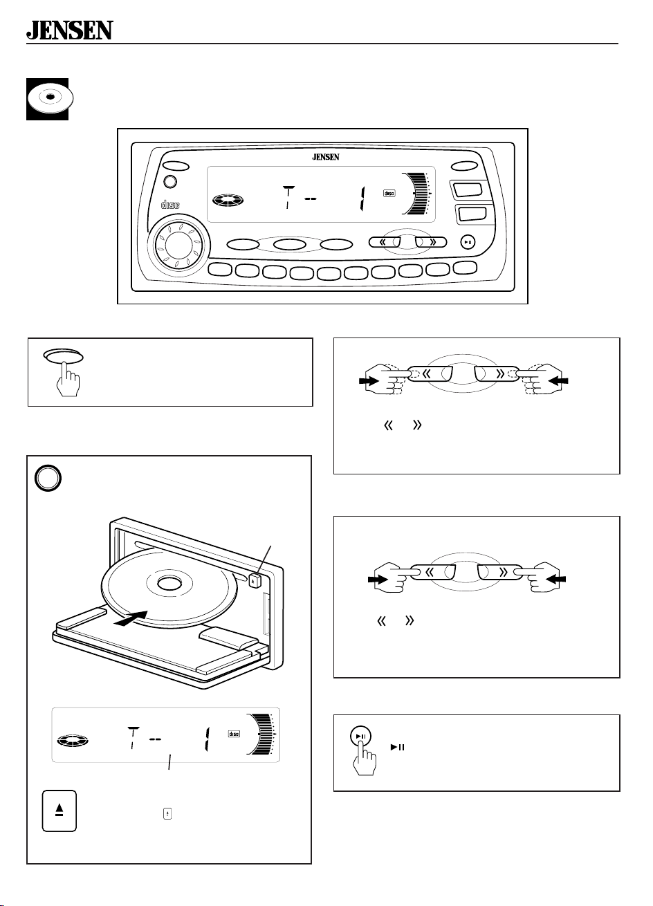
CD Player Operation ................. 8
CD Mode ........................................ 8
Insert and Eject CD ........................ 8
Skip Tracks .................................... 8
Fast Forward and Fast Reverse .... 8
Pause CD ...................................... 8
Intro (Preview all Tracks) ............... 9
Repeat the Same Track ................. 9
Random (Play all Tracks) ............... 9
Direct Track Access ....................... 9
Program CD Tracks ....................... 9
CD Changer Operation ........... 10
CDC Mode ................................... 10
Direct Disc Access ....................... 10
Direct Track Access ..................... 10
Skip Tracks .................................. 10
Fast Forward and Fast Reverse .. 11
Pause CD Changer ...................... 11
Intro (Preview all Tracks) ............. 11
Repeat the Same Track ............... 11
Random (Play all Tracks) ............. 11
Specifications
and Warranty ............................. 12
PWR
COMPACT
DIGITAL AUDIO
REL
SEL MODE BAND
SHIFT TUNE
RDMPGM
AS/PS
CLK
DISP
S.WFR
LOUD
MEM
CLR
RPT
INT
2
1
3
478910
56
®
CH
CDC
MONO
LOC LOUD
STEREO
0
+
+
S.W

2
®
CD515K
Basic Operation
On/Off
Press any button to turn the CD515K
on. Press PWR to turn it off.
Select Function
1. Press and hold
LOUD (S.WFR)
button for more
than one second to
activate Subwoofer.
PWR
S.WFR
LOUD
1
2
VOL
(Fader)
(Balance)
(Treble)
(Bass)
(Volume)
SEL
SEL
SEL
SEL
SEL
(Subwoofer)
SEL
0
+
+
S.W
Note: If the Sub (Subwoofer) is not activated then
the Sub (Subwoofer) function will not display. All
other functions will display in the order indicated.
PWR
COMPACT
DIGITAL AUDIO
REL
SEL MODE BAND
SHIFT TUNE
RDMPGM
AS/PS
CLK
DISP
S.WFR
LOUD
MEM
CLR
RPT
INT
2
1
3
478910
56
®
CH
CDC
MONO
LOC LOUD
STEREO
0
+
+
S.W
2. Press SEL button to move display through
volume, bass, treble, balance, fader and
sub functions.
3
3. Use the volume knob
to adjust the selected
functions. When
function has not been
adjusted for 3 seconds, display returns to
normal radio or CD display.
>2 sec

3
®
CD515K
Bass
1. Press SEL button two
times. BAS appears in
the display.
VOL
Volume
Adjust volume
by turning
volume knob.
1. Press SEL button three
times. TRE appears in
the display.
Treble
2. Adjust bass level by turning volume knob.
2. Adjust treble level by turning volume knob.
–6 = minimum bass
+6 = maximum bass
–0 = flat audio response
–6 = minimum treble
+6 = maximum treble
–0 = flat audio response
+
–
+
–
+
–
0
+
+
1
2
SEL
SEL
0
+
+
0
+
+
SEL
1
2
SEL
SEL
0
+
+
0
+
+
0= minimum volume
46= maximum volume

4
®
CD515K
1. Press SEL button four times.
2. Adjust sound balance left and right by
turning volume knob.
Balance
R12=Right
speaker only
C=Equal sound
right and left
L12=Left
speaker only
1. Press SEL button five times.
2. Adjust sound front and rear by turning
volume knob.
Fader
F12=Front
speakers only
C=Equal sound
front and rear
R12=Rear
speakers only
RL F
R
SEL
SEL
1
SEL
SEL
0
+
+
2
0
+
+
0
+
+
0
+
+
2
0
+
+
0
+
+
0
+
+
SEL
SEL
SEL
1
SEL
SEL
0
+
+

5
®
CD515K
Loudness
Press LOUD to increase bass output.
LOUD will appear in display. Press
LOUD again to deactivate loudness.
Sub (Subwoofer)
1. Press SEL button
six times.
2. Use the volume
knob for gain
adjust.
LOUD
SEL
SEL
SEL
SEL
1
2
SEL
SEL
0
+
+
0
+
+
0
+
+
minimum
maximum
Note: If the Sub (Subwoofer) is not activated,
the Sub (Subwoofer) function will not display.
Mode
MODE
MODE MODE
Press the MODE button to select Radio (TUN),
CD play (CD) or CD Changer (CDC) mode.
The MODE button only selects the CD mode if
a CD is inserted, and only selects the CDC
mode if a Jensen CD Changer is plugged in
and a CD is inserted.
View/Set the Clock
To view the time, press CLK button to
temporarily display clock.
To set the clock:
1. Press CLK button to display clock.
2. Press and hold CLK button for more than
two seconds. The colon will start blinking.
>2 sec
3. Within 3 seconds, press on the TUNE
button to change the hours and to
change the minutes.
CLK
2
CLK
1
TUNE
3
M
H

6
®
CD515K
Radio Operation
Select a Band
Select a Station
Press BAND button
to change radio
between two FM
bands and one AM
band. Each band
stores up to ten
preset stations.
Options for selecting a station
Touch
TUNE or for less than two seconds
to move radio frequency number up or down
one step.
Hold
TUNE or for more than two seconds
to seek the next clear station.
Stereo Reception
STEREO
appears automatically in the display
when you reach a strong signal from an FM
station that is broadcasting in stereo.
BAND
TUNE
or
or
PWR
COMPACT
DIGITAL AUDIO
REL
SEL MODE BAND
SHIFT TUNE
RDMPGM
AS/PS
CLK
DISP
S.WFR
LOUD
MEM
CLR
RPT
INT
2
1
3
478910
56
®
CH
STEREO
0
+
+
TUNE
<2 sec
>2 sec
Radio Mode
Press MODE button one time to
select Radio Mode (TUN).
MODE
MODE

7
®
CD515K
Automatically Store Stations
Store a station:
Ten numbered preset buttons store and recall
stations for each band.
Preset Station Number
1. Select a band (if needed).
2. Select a station.
Recall a station:
1. Select a band (if needed).
2.
Touch
a preset button for
less than two seconds to
select stored station.
<2 sec
3.
Hold
a preset button for two seconds. The
preset station number appears on the
display when station is saved.
Preset Stations
Select ten strong stations and store them in
current band.
Scan stations stored in current band.
Scan Stored Stations
(Preset Scan)
1. Select a band (if needed).
2.
Hold
AS/PS button for
more
than two seconds.
The ten new stations
replace stations already
stored in that band.
1. Select a band (if needed).
2.
Touch
AS/PS for
less
than
two seconds. Radio pauses
for ten seconds at each
station.
Touch
AS/PS again
to stop scanning when
desired station is reached.
<2 sec
>2 sec
>2 sec
RDM PGM DISP
MEM
CLR
RPT
INT
2
1
3
478910
56
3
RDMPGMDISP
MEM
CLR
RPT
INT
2
1
3
478910
56
CH
0
+
+
BAND
2
1
RDMPGMDISP
MEM
CLR
RPT
INT
2
1
3
478910
56
CH
0
+
+
BAND
2
1
AS/PS
BAND
2
1
AS/PS
or
BAND
2
1
TUNE
Band

8
®
CD515K
CD Player Operation
Pause CD
During CD player operation, press
button to pause CD play. PAUS
appears in the display. Press again to
resume play.
Insert and Eject CD
Fast Forward and Fast Reverse
Hold or to fast forward or fast reverse a
track. CD play resumes after you release the
button.
Press REL button to open flip-over
panel. Push a CD into slot. The CD will
begin to play. Flip panel up to close.
Press REL button to open flip-over
panel. Press (EJECT) to stop CD
play and eject CD from slot. Flip
panel up to close.
Insert CD
label side up
Skip Tracks
Press or to advance to next track. Track
number appears for less than 1 second then
the time remaining appears.
Track number
0
+
+
TUNE
TUNE
PWR
COMPACT
DIGITAL AUDIO
REL
SEL MODE BAND
SHIFT TUNE
RDMPGM
AS/PS
CLK
DISP
S.WFR
LOUD
MEM
CLR
RPT
INT
2
1
3
478910
56
®
0
+
+
(High speed audible search)
or
or
x
x
x
x
x
x
x
x
x
x
x
x
x
x
x
x
x
x
x
x
x
x
REL
CD Mode
Press MODE button two times to
select CD Player Mode (CD).
MODE
MODE
Eject
button

9
®
CD515K
Press and hold the INT button for
more than two seconds to play first
ten seconds of each track on current
CD. Press and hold the INT button for
more than two seconds again to stop
intro and listen to track.
Intro (Preview all Tracks)
Repeat the Same Track
Press and hold the RPT button for
more than two seconds to continu-
ously repeat same track. RPT
appears in the display. Press and
hold the RPT button for more than
two seconds again to stop repeat.
Random (Play all Tracks)
Press and hold the RDM button for
more than two seconds to play all
tracks on CD in random order one
time. Press and hold the RDM button
for more than two seconds again to
stop random play.
Note:
•Do not expose CD player to extremely
high or low temperatures.
•Do not drive with ejected CD in the slot.
Use Program function to select up to
24 CD tracks to play in any order.
Program works by allowing you to
select a track number for each spot in
the playing sequence. A CD must be
inserted to use Program.
Program CD Tracks
1. Press or to choose track number.
2. Press MEM/CLR to enter
track number into
memory. Display shows
next track number in
sequence. Continue (up
to 24 times) for all desired
tracks.
3. Press PGM to play CD in
programmed order.
Direct Track Access
While a CD is playing or paused, press a
preset button for less than two seconds to
select the corresponding track number (1–10).
INT
1
RPT
2
RDM
4
RDMPGMDISP
MEM
CLR
RPT
INT
2
1
3
478910
56
<2 sec
PGM
5
Note: Direct access of tracks or discs cannot
be performed while in Program CD function.
>2 sec
>2 sec
>2 sec
1
TUNE
PGM
5
MEM
CLR
6
2
3
MEM
CLR
6
To clear memory, press and hold
MEM/CLR in PGM mode while
CD is playing.
or

10
®
CD515K
CD Changer Operation
The CD515K is designed to control an optional
Jensen 6-disc CD changer.
Direct Disc Access
CDC Mode
Press MODE button three times to
select CD Changer Mode (CDC).
RDMPGM
MEM
CLR
RPT
INT
2
1
3
456
BAND
SHIFT
1
2
1. Press SHIFT (BAND)
button. SHIFT will appear
in the display.
2. Press a preset button (1–6) to select
corresponding disc number. Buttons 7–
10 do not select discs.
Skip Tracks
Press or to advance to next track. The
track number appears for less than 1 second
then the time remaining appears.
or
TUNE
Direct Track Access
While a CD is playing or paused, press a
preset button for less than two seconds to
select the corresponding track number (1–10).
RDMPGMDISP
MEM
CLR
RPT
INT
2
1
3
478910
56
<2 sec
PWR
COMPACT
DIGITAL AUDIO
REL
SEL MODE BAND
SHIFT TUNE
RDMPGM
AS/PS
CLK
DISP
S.WFR
LOUD
MEM
CLR
RPT
INT
2
1
3
478910
56
®
CDC
0
+
+
MODE
MODE

11
®
CD515K
Pause CD Changer
During CD player operation, press
button to pause CD play. PAUS
appears in the display. Press again to
resume play.
Fast Forward and Fast Reverse
Hold or to fast forward or fast reverse a
track. CD play resumes after you release the
button.
or
(High speed audible search)
TUNE
Press and hold the INT button for
more than two seconds to play first
ten seconds of each track on current
CD. Press and hold the INT button for
more than two seconds again to stop
intro and listen to track.
Intro (Preview all Tracks)
Repeat the Same Track
Press and hold the RPT button for
more than two seconds to continu-
ously repeat same track. RPT
appears in the display. Press and
hold the RPT button for more than
two seconds again to stop repeat.
Random (Play all Tracks)
Press and hold the RDM button for
more than two seconds to play all
tracks on CD in random order one
time. Press and hold the RDM button
for more than two seconds again to
stop random play.
INT
1
RPT
2
RDM
4
>2 sec
>2 sec
>2 sec

12
®
CD515K
©1998 Recoton Audio Corporation
Recoton Mobile Electronics
A Division of Recoton Audio Corporation
A RECOTON®COMPANY
1090 Emma Oaks Trail
Lake Mary, Florida 32746
®
FM Tuner
Tuning range ..................................................................................................... 87.5 MHz–107.9 MHz
FM mono sensitivity ................................................................................................................... 12 dBf
50 dB quieting sensitivity (stereo) .............................................................................................. 16 dBf
Stereo separation @ 1 kHz ......................................................................................................... 40 dB
AM Tuner
Tuning range .......................................................................................................... 530 kHz–1720 kHz
Amplifier
Total system power ..................................................................................................... 200 Watts peak
Power output ........................................................................................................... front: 2 x 50 Watts
rear: 2 x 50 Watts
CD Player
Frequency response ...................................................................................................... 20 Hz–20 kHz
General
Power supply .......................................................................................... 11–16 VDC, negative ground
Speaker output impedance ..................................................................................................4–8 Ohms
Specifications subject to change without notice.
Specifications
Limited One Year Warranty–USA and Canada
Length of Warranty. This warranty from Recoton Mobile
Electronics shall be in effect for a period of one year from
the date of the first consumer purchase.
Persons Protected. This warranty will be enforceable by
the original owner and any subsequent owners during the
warranty period so long as proof of date of purchase from
an authorized Jensen dealer is presented whenever
warranty service is required.
What is Covered. Except as otherwise specified below,
this warranty covers all defects in material and workman-
ship in this product. The following are not covered: damage
resulting from accident, misuse, abuse, neglect, product
modification, improper installation, incorrect line voltage,
unauthorized repair or failure to follow instructions supplied
with the product; damage occurring during shipment (claims
must be presented to the carrier); elimination of car static
or other electrical interferences; any product purchased
outside USA or Canada, or on which the serial number
has been defaced, modified or removed.
How You Can Get Service.
U.S. Purchasers. Please telephone Jensen at
1-800-323-4815. We will either inform you of the name
and address of an authorized Jensen repair station which
will service the product or will advise you to send the
product to a factory service center.
Canadian Purchasers. The product should be returned
to the Jensen dealer from whom it was purchased and
such dealer either will service or arrange for service of
the product.
If shipment of the product is required, it should be packed
securely. The original dated bill of sale must always be
included with the product as proof of warranty coverage.
What We Will Pay For. We will pay for all labor and
material expenses required to repair the product, but you
must pay any labor costs for the removal and/or installation
of the product. If the product is shipped for warranty
service, you must prepay the initial shipping charges, but
Jensen will pay the return shipping charges if the product is
returned to an address inside the USA or Canada.
Limitation of Implied or Statutory Warranties and
Conditions. All implied or statutory warranties and
conditions, including warranties or conditions of merchant-
ability, fitness for particular purposes and non-infringement,
are limited in duration to the length of this warranty.
Exclusion of Certain Damages. Jensen’s liability is
limited to the repair or replacement, at our option, of any
defective product and shall not include incidental or
consequential economic damages of any kind.
Some states and/or provinces do not allow limitations on
how long an implied warranty lasts and/or do not allow the
exclusion or limitation of incidental or consequential
damages, so the above limitations and exclusions may not
apply to you.
This warranty gives you specific legal rights, and you may
also have other rights which vary from state to state and
province to province.

How to Install the CD515K AM/FM
Stereo Receiver/CD Player with Optional
CD Changer Control and Detachable
Flip-Over Security Panel
®
Installation............................. 2
Before You Begin Installation ..... 2
Tools and Supplies Needed ....... 2
Speaker Requirements .............. 2
Prepare Radio for
Installation .................................. 2
Adapters for Easier
Installation .................................. 2
•Connections ........................ 3
•Crimp Connections ............. 3
•Upgrading your System ...... 3
Disconnect Battery ..................... 4
Remove Old Radio .................... 4
Wiring ....................................... 5
•Fuse Adapters .................... 5
•Cars with a Single
Speaker Wire ...................... 5
Wiring with a Wiring Adapter ..... 6
Connect Wires ........................... 6
Wiring Color Codes .................... 6
Attach Wires to Radio ................ 6
Install Wiring Inside the Car ....... 6
Wiring Diagram–Advanced
Installation .................................. 7
Testing .................................... 8
Reconnect Battery ..................... 8
Test Power Wiring ...................... 8
View/Set the Clock ..................... 8
Test Antenna Connection ........... 9
Test Memory Wiring ................... 9
Test Speaker Connections ....... 10
Final Installation ....................... 11
Troubleshooting ................ 12
Reset Button ............................ 12
Detachable Flip-Over Panel .... 12
Warranty .............................. 13
Contents
Technical Assistance
For technical assistance with the installation of the
CD515K, call 1-800-323-0221.
Installation
Welcome!
What you're holding in your hands is no ordinary owner's
manual. We've tried to make the instructions in this book
clear and easy to follow.
For your Jensen stereo to work right, it must be installed
correctly. This manual will show you how to install your new
stereo like a pro. It's a good idea to read all of these
instructions before you begin the installation. Most
installations are straightforward and can be handled by a
do-it-yourselfer with the right tools, patience, and the ability
to follow instructions. But, do-it-yourself installation isn't for
everyone. If you still don't feel confident after reading this
book, consider turning the installation job over to someone
better suited to it.
Warranty Service
If your Jensen stereo should ever require service, you will
need to have the original dated receipt. If you ever need to
return the unit for any reason, always include the receipt
with the product.
Final
installation
(page 10)
Install brackets
(page 5)
3
1
Install wiring
(pages 6 and 7)
2
®
DISC
PWR
COMPACT
DIGITALAUDIO
REL
SELMODEBAND
SHIFTTUNE
RDMPGM
AS/PS
CLK
DISP
S.WFR
LOUD
MEM
CLR
RPT
INT
2
1
3
4
CH
CDC
0
+
+
S.W
78910
56
®
MONO
LOCLOUD
STEREO

2
®
CD515K
PWR
COMPACT
DIGITALAUDIO
REL
SELMODEBAND
SHIFTTUNE
RDM PGM
AS/PS
CLK
DISP
S.WFR
LOUD
MEM
CLR
RPT
INT
2
1
3
4
CH
CDC
0
+
+
S.W
78910
56
®
MONO
LOCLOUD
STEREO
Before You Begin Installation
Before you begin, you will need tools, supplies and adapters. It is best to make sure you have
everything you need before you take your dashboard apart.
Installation
Prepare Radio for Installation
Tools and Supplies Needed
Basic Installation:
•Torx type screwdrivers
•Flat and Phillips screwdrivers
•Wire cutters
•Wire strippers
•Tools to remove existing radio (screw-
driver, socket wrench set or other tools)
•Radio removal tool
•Electrical tape
Advanced Installation:
•Soldering iron
•Crimping tool
•Volt meter/12 volt test light
•Solder
•Crimp connectors
•18 gauge wire for power connections
•16-18 gauge speaker wire
Remove transport
screw (you cannot
insert a CD until the
screw is removed)
Put adhesive dot (from
accessory kit) over
transport screw hole
Adapters for Easier Installation
Electrical and dashboard adapters make
installation easier. Purchase adapters from
your local Jensen retailer, electronics store or
car stereo specialty store.
Wiring Harness Adapter
For a basic installation, you can purchase a
wiring harness adapter for your car's existing
radio connectors. This makes installation easy.
Dashboard Adapters
The opening in your dashboard may not match
the size of your Jensen radio. Purchase an
adapter kit for your car.
Antenna Adapter (GM cars)
1990 and newer GM cars have a small
antenna connector. You will need an adapter
when installing this radio in a newer GM car.
Speaker Requirements
Only connect the CD515K to speakers rated in
the load impedance range of 4 to 8 ohms.
Speakers with a load impedance less than 4
ohms could damage the CD515K.

3
®
CD515K
Connections
Good wire connections are very important for
best sound and long-term reliability. Here are
two methods:
Splice
1. Strip 1/2 inch (12 mm) of insulation from
both wires.
2. Wrap wires together
3. Fold wires over
4. Stretch electrical tape tightly over splice.
Professional Tip
Solder
Solder is the best way to connect wires, but it
takes skill and practice. Splice the wires (as
shown above). Before taping, heat the wires
(not the solder). When the wires are warm
enough, touch the solder to the splice. The
solder will flow over the wires. Stretch electrical
tape tightly over splice.
Upgrading Your System
Jensen makes a wide range of car stereo
products that will make your car system
sound better, great or INCREDIBLE!
Better Sound
Install a Jensen tape deck or CD player like
you’re doing now. High power units can
make your existing speakers sound better
and play louder.
Great Sound
Replace your existing speakers with Jensen
speakers. Many of our speakers will fit into
your car without cutting or drilling. You can
also add an amplified graphic equalizer to
tailor the sound to your liking.
INCREDIBLE Sound
Jensen offers a full line of amplifiers, high-
power speakers and subwoofers that can
turn your car into audio dynamite. You can
go loud, louder and loudest by selecting
Jensen components from your retailer.
Professional Tip
Professional Tip
Crimp Connections
Purchase crimp connectors and crimping
tool. Connectors are color coded. This
Jensen radio uses BLUE connectors (14-16
gauge wire).
1. Strip 1/4 inch (6mm) of insulation from
both wires.
2. Insert into connector.
3. Crimp tightly.
You can make permanent splices (using
butt connectors) or select connectors that
can be removed and reinstalled.
1
2
3
4
Rosin core
solder
Heat
wires
not
solder
Strip Wire
1/2" (12mm)
Soldering
iron
Solder
Splice
321
Strip wire
1/4" (6mm)

4
®
CD515K
Disconnect Battery
Before you begin, always
disconnect the battery
negative terminal.
+
–
Remove Old Radio
1. Remove trim to expose chassis.
2. Remove the frame from the dashboard.
3. Unscrew screws from the sides.
4. Disconnect wiring harness and remove radio.
1
3
2
Existing Brackets
and Hardware

5
®
CD515K
Wiring
Important
If wiring connections are made wrong, the unit will not operate properly and it could be damaged.
Follow the installation instructions carefully, or have the installation handled by an experienced
technician.
Professional Tip
Fuse Adapters
No convenient power wire? Install a fuse
adapter having a spade connector.
Fuse
Adapter
Fuse
Crimp on a matching connector and attach:
•Yellow wire–Fuse marked MAIN, BAT
or PWR
•Red wire–Fuse marked ACCY
(accessory), or RADIO
Professional Tip
Cars with a Single Speaker Wire
Some speakers connect to the original
radio with a single wire. Your Jensen radio
requires two wires per speaker. You must
locate each speaker and run a second wire
from the speaker (–) terminal to the radio.
You will probably have to remove interior
trim panels and door sills.

6
®
CD515K
Jensen
Connector
(attach to
back of radio)
Wiring Adapter
(attach to car
wiring harness)
Splices
You can make all
these connections
without even being
in the car
Antenna
adapter for
GM cars
(not supplied)
Antenna
Jack
Receiver
Antenna
extender cable
(not supplied)
1Car Wiring
Harness
Antenna
Extender
Cable
(not supplied)
Car
Antenna
Lead
2
Wiring with a Wiring Adapter
This is the easiest wiring method, because it replaces your existing radio. You will have to buy a wire
harness adapter from your dealer, a car stereo installation shop or electronics store. If you use a wiring
adapter, you can connect all wires to the radio before you even start to take your old radio out.
Connect Wires
Splice, crimp or solder the wires from the
Jensen connector to the wiring adapter. Match
the wires according to the chart (below) and
the wiring adapter instructions.
Attach Wires to Radio
1. After splicing the wiring adapter to the
Jensen connector, attach the connector to
the back of the radio as shown.
2. Attach antenna extender cable (not sup-
plied) and antenna adapter (if needed).
Go to Testing on page 8.
Install Wiring Inside the Car
1. Connect wiring adapter to the car's exist-
ing wiring harness.
2. Connect antenna extender cable (not
supplied) to car antenna lead.
Wiring Color Codes
Function Color
LF–Speaker white/black
LF+ Speaker white
LR–Speaker green/black
LR+ Speaker green
RF–Speaker gray/black
RF+ Speaker gray
RR–Speaker violet/black
RR+ Speaker violet
Power Antenna dark blue
Ground black
Ignition red
Battery yellow
Dimmer orange
Cellular Mute pink

7
®
CD515K
LF
LR
RF
RR
LF–
white/black
white
LF+
RF–
gray/black
gray
RF+
LR–
green/black
green
LR+
RR–
violet/black
violet
RR+
AMP
Amplifier wiring
(See amplifier instructions)
RCA-to-RCA cables
(not supplied)
Sub
Output
+–
Black
Yellow
Pink
Red
AMP
Orange
Filter
Box
10-amp fuse
In-line
Fuse
(1-amp)
Antenna
extender
cable (not
supplied)
Optional
CD Changer
Antenna
Jack
Back of Receiver
Dark Blue
In-line
Fuse
(1-amp)
AMP
Amplifier wiring
(See amplifier instructions)
RCA-to-RCA cables
(not supplied)
Wiring Diagram–Advanced Installation
If you are installing new speakers or amplifiers or replacing an aftermarket installation, use this diagram.
Fuses
When replacing a fuse, make sure new
fuse is correct type and amperage. Using
an incorrect fuse could damage radio.
The CD515K uses one 10 amp (in the
filter box) and two 1 amp fast blow AGC
fuses as part of rear wiring harness.
Memory
Connect to battery or 12 volt power
source that is always live.
The radio will not work if this wire
is not connected.
Accessory
Connect to existing radio wire or
radio fuse.
Ground
Connect to ground terminal or clean,
unpainted metal part of chassis.
Power Antenna
Connect to power antenna or
amplifier. If not used, tape bare
end of wire.
Go to “Testing”on page 8.
Cellular Mute
Dimmer
Connect to
existing
dimmer wire

8
®
CD515K
✓
Testing
Before you finish the installation, you should do the following tests to make sure the wiring is correct
and everything is operating properly.
Test Power Wiring
1. Turn ignition switch on. The display should
light. If not, check the electrical connection
at the yellow and red wires.
2. Press PWR button to turn the receiver on.
You will see the radio display. If not, check
electrical connections to the red and
yellow wires.
3. If equipped, the power antenna should
also operate. If not, check electrical
connections to the dark blue wire.
Reconnect Battery
When wiring is complete,
reconnect the battery
negative terminal.
+
–
View/Set the Clock
To view the time, press CLK button to
temporarily display clock.
To set the clock:
1. Press CLK button to display clock.
2. Press and hold CLK button for more than
two seconds. The colon will start blinking.
>2 sec
CLK
1
CLK
2
TUNE
3
M
H
3. Within 3 seconds, press on the TUNE
button to change the hours and to
change the minutes.
Table of contents
Other Jensen Stereo Receiver manuals