Jepson SHDC 8320 User manual

EN Operating instructions 03 - 20
DE Betriebsanleitung 21 - 40
FR Mode d’emploi 41 - 60
NL Handleiding 61 - 80
ES Instrucciones de servicio 81 - 100
PT Instruções de utilização 101 - 118
IT Istruzioni per l’uso 119 - 137
Certicates 138 - 139
METAL CUTTING CIRCULAR SAW
SHDC 8320 | HDC 8230N | HDC 8200
EN METAL CUTTING CIRCULAR SAW
DE METALLKREISSÄGE
FR SCIE CIRCULAIRE A COUPE DE MÉTAL
NL METAAL CIRKELZAAG
ES SIERRA CIRCULAR PARA CORTE DE METALES
PT SERRA CIRCULAR DE CORTE DE METAL
IT SEGA CIRCOLARE PER IL TAGLIO DEI METALLI

2

EN
DE
FR
NL
ES
PT
IT
GENERAL 4
1. EC DECLARATION OF CONFORMITY SHDC 8320 4
2. EC DECLARATION OF CONFORMITY HDC 8230 & HDC 8200 4
3. SPECIFICATIONS 5
4. USER INSTRUCTIONS 5
5. SAFETY INSTRUCTIONS 6
5.1. ILLUSTRATION OF SAFETY INSTRUCTIONS 6
5.2. GENERAL SAFETY INSTRUCTIONS 6
5.3. SPECIFIC SAFETY RULES 8
SUPER HAND DRY CUTTER 8320 10
6. DESCRIPTION 10
7. FUNCTIONAL DESCRIPTION 11
7.1. INTENDED USE 11
7.2. ELECTRICAL CONNECTION 11
7.3. EXTENSION CABLE 11
7.4. SAW BLADE 11
7.5. UNPACKING 11
7.6. INSTALLING THE SAW BLADE 11
7.7. REMOVING THE BLADE 12
7.8. ADJUST CUTTING DEPTH 12
7.9. USE OF SIGHTING NOTCH 12
7.10. BLADE GUARD 12
7.11. DUST COLLECTION SYSTEM 12
8. START AND STOP OFTHE MACHINE 13
8.1. SWITCHING THE MACHINE ON AND OFF 13
8.2. ELECTRONIC OVERLOAD PROTECTION AND LOAD INDICATOR LIGHT 13
8.3. USE OF THE MACHINE 13
8.4. CUTTING GUIDE 14
9. MAINTENANCE AND REPAIR 14
9.1. KEEP TOOL CLEAN 14
9.2. REPLACEMENT OF CARBON BRUSHES 14
9.3. STANDARD ACCESSORIES 14
HAND DRY CUTTER 8230N | 8200 15
10. DESCRIPTION 15
11. APPLICATION 16
12. FUNCTIONAL DESCRIPTION 16
12.1. UNPACKING 16
12.2. CARTON CONTENTS 16
12.3. INSTALLING THE BLADE 16
12.4. REMOVING THE BLADE 17
12.5. ADJUSTMENT DEPTH OF CUT 17
12.6. ADJUSTMENT OF BEVEL ANGLE 17
12.7. HOW TO USE THE SIGHTING NOTCH 17
12.8. STARTING AND STOPPING TOOL 17
12.9. REMOVING CHIPS 17
12.10. HOW TO USE THE RIP FENCE 17
12.11. LOWER RETRACTING BLADE GUARD 17
12.12. HOW TO USE THE TOOL 18
12.13. CLAMP THE WORK PIECE 18
13. MAINTENANCE 18
13.1. KEEP TOOL CLEAN 18
13.2. THE CARBON BRUSHES 18
13.3. WARNING 18
13.4. STANDARD ACCESSORIES 18
GENERAL 19
14. QUOTATION 19
15. SPARE PARTS 19
16. WARRANTY 19
TABLE OF CONTENTS
3

GENERAL
1. EC DECLARATION OF CONFORMITY SHDC 8320
(according to Appendix IIA of the machine Directive)
We, Jepson Power GmbH, Ernst – Abbe – Straße 5, 52249 Eschweiler, Germany, as the manufacturer
declare herewith under our responsibility that the product:
Name: Super Hand Dry Cutter SHDC 8320
Manufacturing date: See machine label
Serial number: See machine label
complies with the following standards, directives and referenced standard documents:
2006/42/EC Machinery Directive
2014/30/EU EMC Directive
2014/65/EU RoHS Directive
EN 62841-1 :2015 EN 61000-3-2:2014
EN 62841-2-5:2014 EN 61000-3-3:2013
EN 55014-1 :2017
EN 55014-2:2015
Pierre Michiels, Managing Director
Name, Position Eschweiler, 01.08.2021
2. EC DECLARATION OF CONFORMITY HDC 8230 & HDC 8200
(according to Appendix IIA of the machine Directive)
We, Jepson Power GmbH, Ernst – Abbe – Straße 5, 52249 Eschweiler, Germany, as the manufacturer
declare herewith under our responsibility that the product:
Name: Hand Dry Cutter HDC 8230N | Hand Dry Cutter HDC 8200
Manufacturing date: See machine label
Serial number: See machine label
complies with the following standards, directives and referenced standard documents:
2006/42/EC Machinery Directive
2014/30/EU EMC Directive
EN 60745-1 :2009+A11 :2010 EN 55014-2 :1997+A1 :2001+A2 :2008
EN 60745-2-5 :2010 EN 61000-3-2 :2006+A1 :2009+A2 :2009
EN 62233 :2008 EN 61000-3-3 :2008
EN 55014-1 :2006+A1 :2009+A2 :2011
Pierre Michiels, Managing Director
Name, Position Eschweiler, 01.08.2021
GENERAL
4

EN
DE
FR
NL
ES
PT
IT
3. SPECIFICATIONS
Machine SHDC 8320 HDC 8230N HDC 8200
Voltage (see machine label) 230 V / 50 Hz
110 V / 60 Hz
230 V / 50 Hz
110 V / 60 Hz
230 V / 50 Hz
No load speed 1.700 rpm 2.200 rpm 3.700 rpm
Power input 1.800 W 1.700 W 1.700 W
Max. saw blade diameter 320 mm | 12 5/8” 230 mm | 9” 203 mm | 8”
Bevel capability 0° 0°~45° 0°~45°
Arbor hole diameter 25,4 mm | 1“ 25,4 mm | 1“ 25,4 mm | 1“
Max. cutting depth 120 mm | 4.72”
(on guide rail)
90°: 82 mm | 3.22”
45°: 56 mm | 2.20”
90°: 67 mm | 2.63”
45°: 42 mm | 1.65”
Net weight 8,4 kg | 18,5 lbs 7,1 kg | 15,7 lbs 6,3 kg | 13,9 lbs
Noise level ISO1999 DIN45635 99,0 dB (A) 88,5 dB (A) 88,5 dB (A)
Sound pressure level 110,0 db(A) 99,5 db(A) 99,5 db(A)
Hand-arm vibration 1,4 m/s21,0 m/s21,0 m/s2
Information referred to 2.2 of Annex 1 of the E. G. Directive on vibrations)
4. USER INSTRUCTIONS
Notes for the customer
The instruction manual includes important
instructions as to how to operate the machine
safely, correctly and economically. Observing
these instructions helps to avoid risks, repair costs
and downtimes and to increase the reliability and
lifetime of the machine.
The instruction manual must be read and used
by each person who works with the electrical
equipment. This applies in particular to the
“Safety Instructions” chapter. It is too late to read
the manual and safety instructions when work is
actually being carried out at the machine.
Always keep one copy of this manual next to the
machine so that it is at hand ready to be consulted!
In case of any doubt or questions, always contact
the machine manufacturer.
In addition to the instruction manual, the accident
prevention regulations which apply in the country
of use and the user location must be adhered to. In
addition, the recognised technical rules regarding
accident prevention must be observed.
Liability and warranty
All the information contained in this instruction
manual has been drawn up to the best of our
knowledge and belief, taking our experience to date
into consideration.
The original version of this instruction manual was
drawn up in the German language and was checked
by us for accuracy of content. The translation into
the respective national/contractual language was
carried out by a recognised translation agency.
This instruction manual has been put together with
the greatest of care. However, if you should discover
any incomplete items or mistakes, please inform us
in writing. Your suggestions for improvement will
help us to create a user-friendly manual.
Subsequent Orders and Copyright
Further copies of this instruction manual can be
ordered from the address below. We ask for your
understanding that further copies are subject to
charge.
Jepson Power GmbH
Ernst-Abbe-Straße 5
D-52249 Eschweiler
Phone: +49 (0)2403 – 6455-0
Fax: +49 (0)2403 – 6455-15
Mail: [email protected]
All rights are expressly reserved. Duplication or
transfer on to third parties in any form whatsoever
is not allowed without our prior written permission.
GENERAL
5

Abbreviations
V Volt
A Ampere
Hz Hertz
W Watt
~ AC
/min Revolutions per minute rpm
N Newton
5. SAFETY INSTRUCTIONS
The basic prerequisite for safe handling and
disturbance-free operation of this electric tool
is knowledge of the basic safety instructions.
In addition, the accident prevention rules and
regulations which apply in the user location must
be adhered to, as well as the recognized rules of
the trade with regard to safety and correct working
methods.
It is not permitted to use the electric tool for other
purposes than those intended by the manufacturer.
Such use could give rise to unforeseeable risks.
Local working and safety rules and laws must always
be followed. The same applies to regulations which
apply to the environment.
Safety equipment must never by removed or
bridged over.
When using oils, greases and other chemical
substances, the safety regulations which apply to
the particular product must always be observed!
Contact with chemicals should be avoided as far
as possible. Before it is permissible to work with
these substances the instructions for use on the
packaging must be read and followed. This applies
for all chemicals, therefore also for cleaning media.
All notes and signs regarding safety and possible
risks must be kept in a fully legible condition.
5.1. ILLUSTRATION OF SAFETY INSTRUC
TIONS
The following symbols are used in the instruction
manual:
Warning against possible danger of
injury or danger to life for persons
Warning against possible damage to
property or the environment
Warning against dangerous electrical
voltage
Warning against hot surfaces
Ignoring these instructions can lead to serious
damage to health, up to life-threatening injuries!
This symbol indicates important
information
Hazardous to the environment
5.2. GENERAL SAFETY INSTRUCTIONS
This electric tool fulls the basic EC
safety and health regulations.
Nevertheless, dangerous situations
can arise.
All safety equipment must be
maintained in perfect condition.
Always pay attention to moving
parts. These can cause injury because
of their movement or by sudden
movement.
Only use the electric tool when it is in
perfect condition from the technical
point of view, and only use it for
intended purpose while being aware
of safety issues and risks, and paying attention
to the instruction manual! In particular, have any
disturbances which could have a negative eect
on safety corrected immediately!
WARNING! It is essential to read all the
instructions. Mistakes which are made while
attempting to follow the below instructions can
cause electric shock, re and/or serious injury.
The following term “Electric tool”, refers to
mains-powered electric tools (with mains cable)
and battery-powered electric tools (without
mains cable).
GENERAL
6

EN
DE
FR
NL
ES
PT
IT
KEEP THESE INSTRUCTIONS IN A
SAFE PLACE.
Work Area Safety
Keep your work area clean and well lit. Cluttered
benches and dark areas invite accidents.
Do not operate power tools in explosive
atmospheres, such as in the presence of ammable
liquid, gases, or dust. Power tools create sparks,
which may ignite the dust or fumes.
Keep bystanders, children, and visitors away while
operating a power tool. Distractions can cause you
to lose control.
Electrical Safety
Earthed tools must be plugged into an outlet
properly installed and earthed in accordance
with all codes and ordinances. Never remove the
earthing prong or modify the plug in any way. Do
not use any adaptor plugs. Check with a qualied
electrician if you are in doubt as to whether the
outlet is properly earthed. If the tools should
electrically malfunction or break down, earthing
provides a low resistance path to carry electricity
away from the user.
Avoid body contact with earthed or grounded
surfaces such as pipes, radiators, ranges and refrig-
erators. There is an increased risk of electric shock if
your body is earthed or grounded.
Don’t expose power tools to rain or wet conditions.
Water entering a power tool will increase the risk of
electric shock.
Don’t abuse the cord. Never use the cord to carry
the tools or pull the plug from an outlet. Keep cord
away from heat, oil, sharp edges or moving parts.
Replace damaged cords immediately. Damaged or
entangled cords increase the risk of electric shock.
When operating a power tool outside, only use
authorized cords for outdoor work. These cords are
rated for outdoor use and reduce the risk of electric
shock.
If operating a power tool in a damp location is
unavoidable, use an earth leakage circuit breaker.
Use of an earth leakage circuit breaker reduces the
risk of electric shock.
Personal Safety
Stay alert, watch what you are doing and use
common sense when operating a power tool. Do
not use tool while tired or under the inuence
of drugs, alcohol, or medication. A moment of
inattention while operating power tools may result
in serious personal injury.
Use safety equipment. Always wear eye protection.
Safety equipment such as dust mask, non-skid
safety shoes, hardhat, or hearing protection used for
appropriate conditions will reduce personal injuries.
Avoid accidental starting. Be sure switch is o-po-
sition before connecting to power source, picking
up or carrying the tool. Carrying tools with your
nger on the switch or plugging in tools that have
the switch on invites accidents
Remove any adjusting key or wrenches before
turning the tool on. A wrench or a key that is left
attached to a rotating part of the tool may result in
personal injury.
Do not overreach. Keep a proper footing and
balance at all times. Proper footing and balance
enables better control of the tool in unexpected
situations.
Dress properly. Do not wear loose clothing or
jewellery. Keep your hair, clothing and gloves away
from moving parts. Loose clothes, jewellery or long
hair can be caught in moving parts.
Tool use and care
Do not force tool. Use the correct tool for your
application. The correct tool will do the job better
and safer at the rate for which it is designed.
Do not use tool if switch does not turn it on and o.
Any tool that cannot be controlled with the switch
is dangerous and must be repaired.
Disconnect the plug from the power source before
making any adjustments, changing accessories, or
storing the tool. Such preventive safety measures
reduce the risk of starting the tool accidentally.
Store idle tools out of reach of children and do not
allow persons unfamiliar with the power tool or
GENERAL
7

these instructions to operate the power tool. Tools
are dangerous in the hands of untrained users.
Maintain tools with care. Keep cutting tools sharp
and clean. Properly maintained tools, with sharp
cutting edges are less likely to bind and are easier
to control.
Maintain power tools. Check for misalignment or
binding of moving parts, breakage of parts, and any
other condition that may aect the tools operation.
If damaged, have the tool serviced before using.
Poorly maintained tools cause many accidents.
Use the power tool, accessories and blades etc.,
in accordance with these instructions and in the
manner intended for the particular type of power
tool, taking into account the working conditions
and the work to be performed. Use of the power
tool for operations dierent from those intended
could result in a hazardous situation.
Use clamps or other practical way to secure and
support the work piece to a stable platform. Holding
the work by hand against your body is unstable and
may lead to loss of control.
Use only accessories that are recommended by the
manufacturer for your model. Accessories that may
be suitable for one tool may become hazardous
when used on another tool.
Service
Only qualied repair personnel must perform
tool service. Service or maintenance performed
by unqualied personnel could result in a risk of
injury.
When servicing tool, use only identical
replacement parts. Follow instructions in
the maintenance section of this manual. Use
of unauthorized parts or failure to follow
maintenance Instructions may create a risk of
electric shock or injury.
5.3. SPECIFIC SAFETY RULES
DANGER: Keep hands away from cutting area and
blade. Keep your second hand on auxiliary handle. If
both hands are holding the saw, they cannot be cut
by the blade.
WARNING! Do not reach underneath
the work. The guard cannot protect
you from the blade below the work.
Adjust the cutting depth to the thickness of the
workpiece. Less than a full tooth of the blade
teeth should be visible below the workpiece.
NEVER hold piece being cut in your hands or
across your leg. It is important to support the
work properly to minimize body exposure, blade
binding, or loss of control.
WARNING! Hold tool by insulated
gripping surfaces when performing
an operation where the cutting tools
may contact hidden wiring or its own
cord. Contact with a “live” wire will make
exposed metal parts of the tool “live” and shock
the operator.
When ripping, always use a rip fence or straight
edge guide. This improves the accuracy of cut and
reduces the chance of blade binding. Always use
blades with correct size and shape of arbour holes.
Blades that do not match the mounting hardware
of the saw will run eccentrically, causing loss of
control.
WARNING! Never use damaged or
incorrect arbor anges or bolts. The
arbor anges and bolt were specially
designed for your saw, for best
performance and safety of operation
Important: Kickback causes and related
warnings
Kick back is a sudden reaction to a
pinched, bound or misaligned saw
blade, causing an uncontrolled saw to lift up and
out of the workpiece toward the operator;
When the blade is pinched or bound tightly by the
kerf closing down, the blade stalls and the motor
reaction drives the unit rapidly back toward the
operator;
Kickback is the result of saw misuse and/or incorrect
operating procedures or conditions and can be
avoided by taking proper precautions as given
below.
Maintain a rm grip with both hands on the saw
and position your arms to resist kickback forces.
Position your body to either side of the blade, but
not in line with the blade.
Kickback could cause the saw to jump backwards,
but kickback forces can be controlled by the
operator, if proper precautions are taken.
GENERAL
8

EN
DE
FR
NL
ES
PT
IT
When blade is binding, or when
interrupting a cut for any reason,
release the trigger and hold the saw
motionless in the material until the
blade comes to a complete stop. Never attempt
to remove the saw from the work or pull the saw
backward while the blade is in motion or
KICKBACK may occur. Investigate and take
corrective actions to eliminate the cause of blade
binding.
When restarting a saw in the workpiece,
center the saw blade in the kerf and
check that teeth are not engaged into
the material.
If saw blade is binding, it may walk up or KICKBACK
from the workpiece as the saw is restarted.
Support large panels to minimize the risk of blade
pinching and KICKBACK. Large panels tend to sag
under their own weight. Supports must be placed
under the panel on both sides, near the line of
cut and near the edge of the panel. Do not use dull
or damaged blade. Dull blades produce a narrow
kerf causing excessive friction, blade binding, and
KICKBACK.
Blade depth and bevel adjusting locking levers
must be tight and secure before making cut. If
blade adjustment shifts while cutting, it may cause
binding and kickback.
Use only recommended blades, rated
at the machine’s maximum rated RPM
or higher with correct arbor hole.
Guard function
Check guard for proper closing before each use. Do
not operate the saw if guard does not move freely
and enclose the blade instantly. Never clamp or
tie the guard so that the blade is exposed. If saw is
accidentally dropped, guard may be bent. Check
to make sure that guard moves freely and does not
touch the blade or any other part, in all angles and
depths of cut.
Check the operation and condition of
the guard return spring. If the guard
and the spring are not operating
properly, they must be serviced before
use. Guard may operate sluggishly due to damaged
parts, gummy deposits, or a build-up of debris.
Lower guard may be retracted manually only
for special cuts such as “plunge cuts”. Raise
lower guard by projecting portion and as soon
as blade enters the material, the lower guard
must be released. For all other sawing, the lower
guard should operate automatically.
Always observe that the guard is
covering the blade before placing
saw down on bench or oor.
An unprotected, coasting blade will cause the
saw to walk backwards, cutting whatever is in its
path. Be aware of the time it takes for the blade
to stop after switch is released.
Tighten blade retaining bolt and all clamps before
operating.
Secure workpiece properly. Workpiece should
be straight and rmly clamped to avoid possible
movement and pinching as the cut nears
completion.
Allow the blade to come to a
complete stop before removing or
securing workpiece, or changing
workpiece angle.
Check the inside surfaces of the arbor anges as
well as the sides of the blade for freedom from any
foreign matter.
Check the blade for cracks or other damage before
operation. Replace cracked or damaged blade
immediately.
Never start the tool with the workpiece against the
blade.
Allow the motor to achieve full speed before
cutting.
Important: After completing the cut, release
power switch and wait for coasting blade to stop
completely before putting the saw down.
Never operate the tool in an area with ammable
solids, liquids, or gases. Sparks from the
commutator/carbon brushes could cause a re or
explosion.
There are certain applications for which this
tool was designed. The manufacturer strongly
recommends that this tool NOT be modied and/
or used for any application other than for which it
was designed. If you have any questions relative to
its application DO NOT use the tool until you have
written the manufacturer and have been advised
WARNING: Always wear hearing protection with
this tool.
GENERAL
9
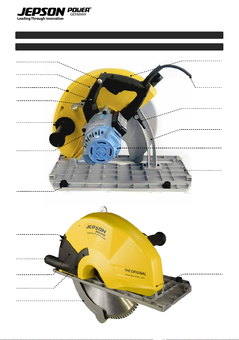
SUPER HAND DRY CUTTER 8320
6. DESCRIPTION
Arbor lock lever
Dust extractor port
Dust chamber cover
Guide clearance adjustor
L - hex key
stored in main handle
Load indicator light
Lock release button
Clip
Dust port cap
Lower blade guard
Depth lock lever
Depth lock scale
Motor unit
Base plate
Upper blade guard
Main handle
Power supply cable
Kick lever
Side handle
SUPER HAND DRY CUTTER 8320
10

EN
DE
FR
NL
ES
PT
IT
7. FUNCTIONAL DESCRIPTION
7.1. INTENDED USE
This saw is designed exclusively for the
sawing of rigid insulation panel,
sandwich panel, aluminum, steel and
plastics. This machine should not be
used for cutting other materials. Do not use this saw
to cut wood. The machine should not be converted
or modied, e.g. for any other form of use, other
than as specied in these operating instructions.
The user shall be liable for damages and accidents
due to incorrect use.
CAUTION: Do not overheat the blade
tips. Use of undue force will not
speed up the cutting operation.
Allow the tool to determine the best
feed rate.
CAUTION: When sawing plastics, avoid melting
the plastic.
7.2. ELECTRICAL CONNECTION
The network voltage must conform to
the voltage indicated on the tool name
plate. Under no circumstances should
the tool be used when the power
supply cable is damaged. A damaged cable must be
replaced immediately by an authorized Customer
Service Center. Do not try to repair the damaged
cable yourself. The use of damaged power cables
can lead to an electric shock.
7.3. EXTENSION CABLE
If an extension cable is required, it must
have a sucient cross-section so as to
prevent an excessive drop in voltage or
over-heating. An excessive drop in
voltage reduces the output and can lead to failure
of the motor. The following table shows you the
correct cable diameter as a function of the cable
length for this machine. Use only U.L. and CSA listed
extension cables. Never use two extension cables
together. Instead, use one long one
Total Extension Cord
Length (feet) Cord Size (AWG)
25 16
50 12
100 10
150 8
200 6
7.4. SAW BLADE
Only use original saw blades with a
diameter in accordance with the
markings on the tool name plate:
Only use saw blades with blade set
(cutting width) of 2.2 mm and blade thickness 1.8
mm.
Saw blades must be suitable for speeds of up to
1700 min -1or faster. Do not use any abrasive wheel
with this machine.
7.5. UNPACKING
Carefully remove the tool and all loose items from
the shipping container. Retain all packing materials
until after you have inspected and satisfactorily
operated the machine.
NOTE: An appropriate blade must be mounted
to the machine before operating. Refer to the
section of this manual: “INSTALLING THE SAW
BLADE”
Carton contents:
• SUPER Hand Dry Cutter 8320
• Original Jepson carbide tipped saw blade
320x2.2x25.4x84T
• M5 L-hex key
WARNING! DO NOT OPERATE THIS
TOOL UNTIL YOU READ AND
UNDERSTAND THE ENTIRE
INSTRUCTION MANUAL
7.6. INSTALLING THE SAW BLADE
Inner arbor ange ENSURE THAT THE MACHINE IS
DISCONNECTED FROM POWER
SOURCE
To install the blade:
Remove any accumulated debris in
the guards and around the arbor.
Clean the inner arbor ange. Orient the ange so
that the correct side faces the blade and place the
new blade on the arbor,
making sure that the teeth point forwards.
Place the outer arbor ange on the arbor with the
correct side toward the blade.
NOTE: Use blades that have an arbor bore which
can t, and that are rated for the machine’s
SUPER HAND DRY CUTTER 8320
11

maximum rated speed or higher. Avoid contact
with blade teeth to prevent personal injury.
NOTE: Take care to ensure that the blade is
centered (it is possible to tighten the blade
crooked between the anges).
Replace and nger-tighten the blade retaining bolt
by turning it clockwise.
Arbor lock lever Push in the arbor lock lever and
rotate the arbor by hand until the
lock engages the arbor. Tighten
the blade retaining bolt securely.
Rock the arbor with the wrench to
ensure that the arbor lock has
released and release the arbor lock.
7.7. REMOVING THE BLADE
DISCONNECT THE MACHINE FROM POWER
SOURCE.
Removal is the opposite of installing the blade, but
special care must be taken to avoid injury from the
blade.
Push in the blade lock lever and rotate the arbor
with the wrench on the retaining bolt until the lock
engages the arbor. Loosen the blade retaining bolt
with the provided wrench and release the arbor
lock.
Completely unscrew the blade retaining bolt and lift
it and the outer ange away, taking care not to drop
the blade.
Carefully rotate the lower blade guard out of the
way. The blade may now be removed.
7.8. ADJUST CUTTING DEPTH
DISCONNECT THE MACHINE FROM POWER
SOURCE.
Depth lock lever
Adjust the cutting depth as
desired. A depth scale is provided.
Loosen the depth lock lever and
set the depth to the desired level.
Then tighten the lever.
Depth lock scale
WARNING: Depth adjusting locking
lever must be tight and secure
before making cut. If blade
adjustment shifts while cutting, it may cause
binding and kickback.
7.9. USE OF SIGHTING NOTCH
Sighting notch To aid in free-hand cutting, a
sighting notch is located at the
front of the base.
Align the cutting line on the
work-piece with the sighting
notch. Additionally, the blade is
visible through small gaps in the cover for aligning
the blade perfectly with the intended line of cut.
7.10. BLADE GUARD
To test the function of the lower blade guard, rotate
the guard through the full stroke of its travel and
ensure that the guard is able to fully return back to
the closed position under its own spring tension.
If the guard is found to be sluggish or if it sticks in
any position, the problem will need to be remedied
before the machine is used again. It usually just
needs to be cleaned. To clean, rst remove the
sawblade and then clean all around the rotating
joint of the guard. All other repairs should be
performed by an authorized service center.
Kick lever Kicker Lever: When cutting
materials with bigger dimension/
cutting depth , such as sandwich
panel, often the lower blade guard
will not be able to bump open
automatically. In this case the
Lower blade guard kicker lever may be used to allow
the lower blade guard to open just
enough to get started. Simply
push the lever with the thumb of
the left hand without removing
one’s hand from the side handle.
After it begins, allow the guard to function automat-
ically as usual.
7.11. DUST COLLECTION SYSTEM
Dust collection should always be used to minimise
dust. Attach an appropriate hose and vacuum
cleaner system to the dust extractor port on the
machine.
Dust chamber If a vacuum cleaner is not available,
close the cap of the dust port.
There is a dust chamber which can
collect a small amount of dust or
chips which is built into the upper
blade guard. Clear the dust
chamber frequently to avoid it being overlled. To
SUPER HAND DRY CUTTER 8320
12

EN
DE
FR
NL
ES
PT
IT
clear the dust chamber, push up on the clip and
rotate the dust chamber cover to the open position
and dump out the dust. Once nished clip the cover
back to the closed position.
8. START AND STOP OF THE
MACHINE
Make sure that the power circuit voltage is the
same as that shown on the specication plate of the
machine and that switch is “OFF” before connecting
the tool to the power circuit.
8.1. SWITCHINGTHE MACHINE ON AND OFF
Keep the machine steady during switching and
during use by holding the main handle and the side
handles with both hands.
Lock release button To switch on: rst push the lock
release button , and then press the
trigger switch.
Trigger switch To switch o:
Release the trigger switch. After the machine has
been switched o, the sawblade will still rotate for a
time. Take care that parts of your body do not come
in contact the saw blade while it is still rotating!
As soon as you remove the machine from the
work-piece, always allow the lower blade guard to
close completely. In this way the sawblade is again
completely covered by the outer protective cover
8.2. ELECTRONIC OVERLOAD PROTECTION
AND LOAD INDICATOR LIGHT
Load indicator light This machine is equipped with a
load indicator light that will inform
the operator of load conditions.
Whenever the switch is turned on
and load conditions are normal,
the indicator light will be a solid
green color. If load is approaching overload
conditions, the indicator light will ash red. I f the
operator continues to run the machine in overload
conditions for a sustained period of time, the
electronic overload protection unit will shut the
machine o. The higher the level of overload, the
more quickly the machine will shut down.
When this happens, always remove the machine
from the work-piece and run the machine at no load
for a few minutes to allow the motor to cool down
before continuing to avoid a burn out of the motor.
8.3. USE OF THE MACHINE
Eective control of this powerful saw requires
two-handed operation for maximum protection.
Do not use this tool continuously over 30 minutes.
Support the work properly and hold the saw rmly
WITH BOTH HANDS to prevent loss of control which
could cause personal injury. Always hold the side
handle with the left hand and the rear handle with
the right hand for proper hand support of the saw.
Protect your eyes from injury with safety glasses or
goggles. Do not use cutting uids or lubricants on
the blade.
Sawing
The machine must reach full speed before cutting
begins and should only be switched o once cutting
has nished. Only operate the saw away from you
(pushing the circular saw forwards) and never
towards you (pulling the circular saw backwards). If
you saw towards you, there is the danger that the
circular saw might be accelerated out of the cutting
groove (recoil) and cause serious injury.
The lower blade guard should open automat-
ically when it hits the edge of the work-piece. If it
doesn’t open automatically, give it a little help at
the beginning of the cut by pushing the kicker lever
with the thumb of the left hand. This will open the
lower blade guard by about 20 degrees.
Sawing sections:
Make sure the cutting depth is set as desired. Place
the front part of the saw bench on the work-piece.
Switch the machine on. Push the machine in the
direction of cut. Take care that the saw base remains
rmly on the work-piece. Switch the machine o
and allow the lower blade guard to close completely
when cutting is completed. The depth is there to
adapt the position of the saw blade on the material.
Clamping the workpiece
Secure the work-piece properly. The work-piece
should be straight and rmly clamped to avoid
possible movement and pinching as the cut nears
completion. Provide adequate support for long
or wide work-pieces. Never position large or long
work-pieces so that they bend in the middle or
at the cutting face. This can lead to the saw blade
jamming and kicking back. Instead, support the
work-piece with several wooden battens, close to
the cutting face. Conrm that the blade has come
to a complete stop before removing or securing the
work-piece, or changing the work-piece angle.
SUPER HAND DRY CUTTER 8320
13
CAUTION: Keep the cord away from
cutting area to prevent it from
becoming entangled in the
work-piece.
Do not force the cut. Let the saw do the cutting at
the rate of speed permitted by the type of cut and
work-piece.
8.4. CUTTING GUIDE
Guide clearance adjustor
Guide rails are available to assist in
making precise straight cuts and
enhance safety. (These are an
optional accessory) The guide rail
may be secured with C-clamps if
desired. There are 2 guide
clearance adjustors for optimum t and safety.
Adjust these equally so that there is no looseness,
yet the base still slides freely.
The rubber sighting strip:
The sighting / anti-splinter strip must be cut to size
along its full length before the rst use. The rubber
strip must be backed by a work-piece when it is cut
for the rst time.
CAUTION: Failure to use a backing work-piece on
the rst cut may result in the rubber strip being
torn or damaged by the blade
Once it is cut to size, it will perfectly correspond
to the cutting edge and will also help to protect
the material from splintering. Once it is sized, the
operator can know at a glance exactly where the
line of cut will be. This saves a lot of time and eort
in making precise cuts.
9. MAINTENANCE AND REPAIR
9.1. KEEP TOOL CLEAN
Periodically blow out all air passages with dry
compressed air. All plastic parts should be cleaned
with a soft damp cloth. NEVER use solvents to
clean plastic parts. They could possibly dissolve or
otherwise damage the material.
Wear safety glasses while using compressed air.
Clean all parts of the lower blade guard mechanism
to ensure smooth operation.
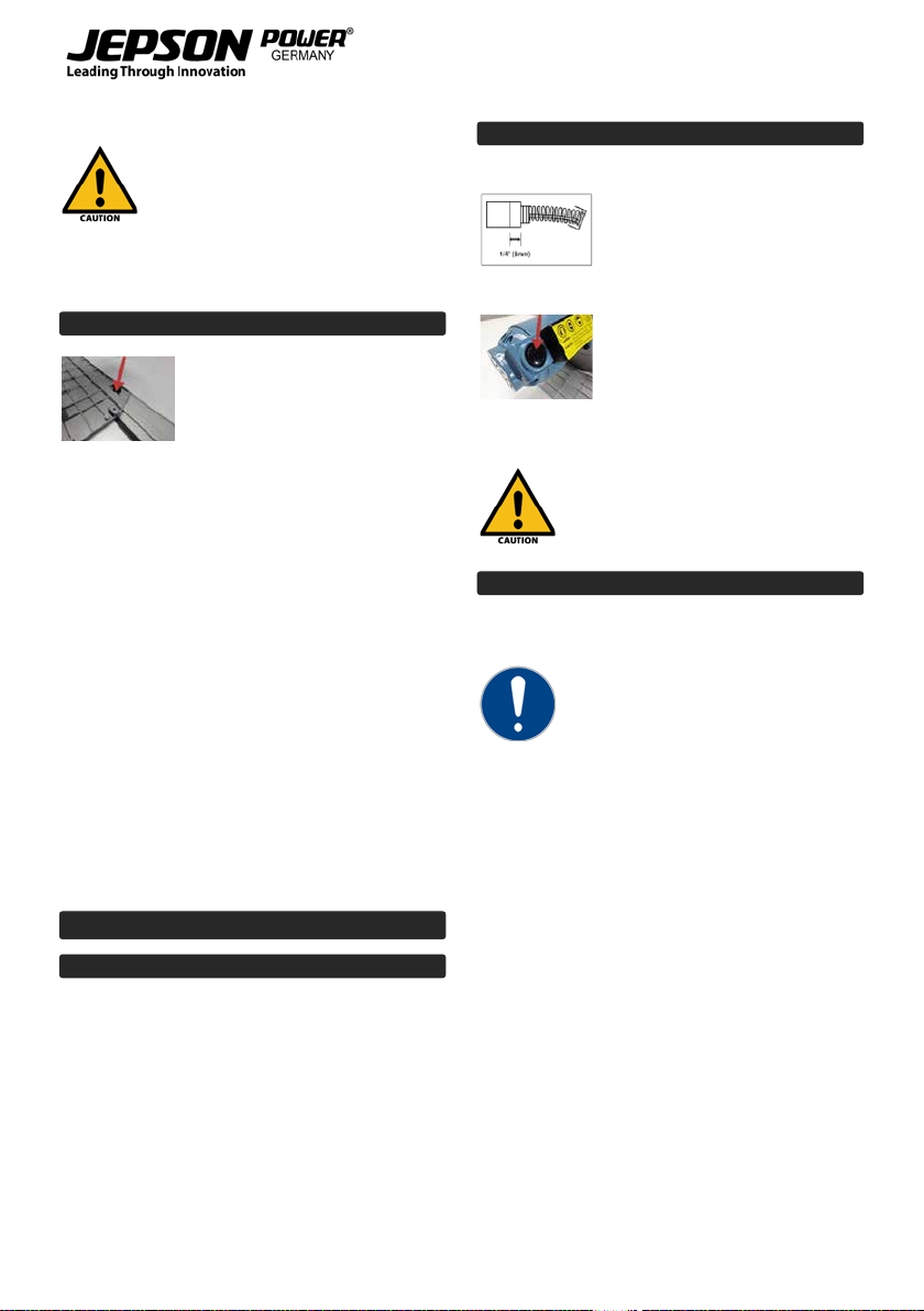
9.2. REPLACEMENT OF CARBON BRUSHES
The carbon brushes are a normal
wearing par t and must be
replaced when they reach their
wear limit.
To replace:
Kohlebürstenhalter Remove the brush caps and
withdraw the old brushes. Replace
with new brushes (always replace
as a pair) ensuring that they align
properly and slide freely. Instal-
lation is the reverse of removal.
Then replace the brush caps.
CAUTION: Always replace the brushes
as a pair.
9.3. STANDARD ACCESSORIES
• Carbide tipped saw blade 320x84T
• 5 mm L-hex key
If the replacement of the power supply
cord is necessary, this has to be done by
the manufacturer or their agent in
order to avoid a safety hazard
SUPER HAND DRY CUTTER 8320
14
EN
DE
FR
NL
ES
PT
IT
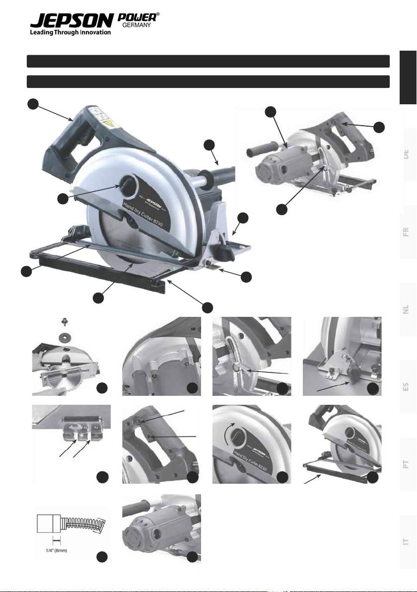
HAND DRY CUTTER 8230N | 8200
10. DESCRIPTION
2
2
6
10
45° 90°
3
7
11
4
8
5
9
1
3
4
5
6
7
8
9
10
11
HAND DRY CUTTER 8230N | 8200
15

11. APPLICATION
1. Do not use abrasive wheels with this machine.
Use only original Jepson Power saw blades
2. Tighten blade retaining bolt and all clamps
before operating.
3. Secure work piece properly. Work piece should
be straight and rmly clamped to avoid
possible movement and pinching as the cut
nears completion.
4. Allow the blade to come to a complete stop
before removing or securing workpiece, or
changing workpiece angle.
5. Check the inside surfaces of the arbor anges
as well as the sides of the blade for freedom
from any foreign matter.
6. Check the blade for cracks or other damage
before operation. Replace cracked or damaged
blade immediately.
7. Never start the tool with the work piece
against the blade.
8. Allow the motor to achieve full speed before
cutting.
9. After turning tool “ON”, gently push the tool
forward to engage work piece, then slowly
increase pressure as required to produce the
least amount of“sparking”.
10. Important: After completing the cut, release
power switch and wait for coasting blade to
stop completely before putting the saw down.
11. Never operate the tool in an area with
ammable solids, liquids, or gases. Sparks or
hot fragments could cause a re or explosion.
12. This tool is designed for ferrous metals
only. Do not attempt to cut wood, masonry,
magnesium, or any other pyrophoric materials
with this tool.
13. Do not use cutting uids or lubricants on the
blade.
14. Some metals have coatings, which can be
toxic. Take extra care to prevent inhalation
and skin contact when working with these
materials. Request, and follow, any safety
information available from your material
supplier.
15. There are certain applications for which this
tool was designed. The manufacturer strongly
recommends that this tool NOT be modied
and/ or used for any application other than
for which it was designed. If you have any
questions relative to its application DO
NOT use the tool until you have written the
manufacturer and have been advised.
Metal chips are often very sharp and hot. Never
touch them with bare hands. Clean up with a
magnetic chip collector and a chip hook or other
appropriate tool.
12. FUNCTIONAL DESCRIPTION
This machine is a dry cutting circular saw designed
to cut ferrous metals, which uses carbide tipped saw
blades. The saw should only be used with original
Jepson Power saw blades.
12.1. UNPACKING
Carefully remove the tool and all loose items from
the shipping container. Retain all packing materials
until after you have inspected and satisfactorily
operated the machine.
12.2. CARTON CONTENTS
1. Metal cutting saw
2. Original Jepson Power carbide tipped saw
blade
3. Rip fence cutting guide
4. Hex wrench
12.3. INSTALLING THE BLADE
1. Disconnect tool from power source.
2. Remove any accumulated debris in the guards
and around the spindle. Check the lower
retracting blade guard to ensure that it is in
working order.
3. Clean the inner spindle ange. Orient the
ange so that the correct bore size faces the
blade and place the new blade on the spindle,
making sure that the teeth point forwards. (If
in doubt of the orientation of the blade, refer
to the legend cast into the lower retracting
blade guard) Avoid contact with blade teeth
to prevent personal injury.
4. NOTE: Only use original Jepson Power saw
blades.
5. Place the outer spindle ange on the spindle
with the at side toward the blade. See g. 2.
6. Replace and nger- tighten the blade retaining
bolt by turning it clockwise.
7. Push in the blade lock lever and rotate the
spindle by hand until the lock engages the
spindle See g. 3. Tighten the blade retaining
bolt securely with the provided wrench and
release the spindle lock.
HAND DRY CUTTER 8230N | 8200
16

EN
DE
FR
NL
ES
PT
IT
12.4. REMOVING THE BLADE
1. Disconnect tool from power source.
2. See g. 3. It is not necessary to remove the
outer blade cover, just leave it in place. Push
in the spindle lock and using the supplied
hex wrench, rotate the blade until the lock
engages the blade spindle.
3. Avoid contact with the blade teeth to prevent
personal injury.
4. While holding the blade lock lever, use the
provided wrench to loosen the blade retaining
bolt. Then remove it and the outer spindle
ange.
5. The blade may now be carefully removed.
12.5. ADJUSTMENT DEPTH OF CUT
Adjust the depth of cut so that the saw blade
protrudes through the thickness of work piece. To
adjust the depth of cut:
1. Disconnect tool from power source.
2. Lift the depth lock lever at the rear of the saw.
See g. 4.
3. Raise or lower the saw base until the blade
extends the desired depth below the base.
(See the scale and pointer cast into the main
body casting.)
4. Press the depth lock lever down rmly, locking
the saw in the selected position.
12.6. ADJUSTMENT OF BEVEL ANGLE
To adjust the bevel angle, refer to the bevel gauge
on the base. There are markings for dierent angles
from 0 to 45 degrees. To adjust the bevel angle:
Loosen the bevel lock knob
( See g. 5 ) and the smaller knob at the rear. Lift the
bevel lock knob out of the slot and rotate the base
to the desired angle. The most commonly used
angles each have an individual slot. Simply drop the
bevel lock into the slot and tighten. If other angles
are needed, tighten the bevel lock knob to hold at
the desired position. Then tighten the smaller knob
at the rear of the base.
12.7. HOW TO USE THE SIGHTING NOTCH
To aid in free- hand cutting, a sighting notch is
located at the front of the base. See g. 6. Align
the cutting line on the work piece with the sighting
notch. Make the cut. Use the right-
hand notch (between the two marking dots) for
straight cuts and the left- hand notch (located
below the rivet) for 45- degree bevel cuts.
12.8. STARTING AND STOPPING TOOL
Make sure that the power circuit voltage is the same
as that shown on the specication plate
of the machine and that switch is “OFF” before
connecting the tool to the power circuit. To start
the machine, rst press the safety lock button
then squeeze the trigger switch to start the motor.
Release the trigger switch to stop the motor. See
g. 7.
12.9. REMOVING CHIPS
This dry- cut metal saw has an internal chip
collector. When the chip collector is full, the chips
must be cleared. To do this, rst shut down and
DISCONNECT TOOL FROM POWER SOURCE. The
outer blade cover lock knob has a bayonet lock
thread. See g. 8. To remove cover, turn knob
anticlockwise while pushing in against the spring
tension. Then lift cover away. Recently- cut chips can
be very hot. Take care when removing the cover to
keep the chips or shavings away from your hands or
other body
parts. Do not throw hot debris where paper or other
ammable materials are located. To replace the
outer blade cover, line up tang with slot and push in
against the spring while turning clockwise. Ensure
that the cover is properly seated.
12.10. HOW TO USE THE RIP FENCE
Using the rip fence will provide more accurate
straight cuts than by cutting free- hand. For instal-
lation, DISCONNECT TOOL FROM POWER SOURCE
then insert the rip fence in the mounting slots. In
the base.
12.11. LOWER RETRACTING BLADE GUARD
The lower retracting blade guard is a safety device
important for your protection. Every
time you use the saw, make sure that the guard
rotates freely and returns quickly and completely
to its closed position. Before each use, remove
any accumulated chips, or shavings from the area
around the hub of the guard. DO NOT LUBRICATE
THIS AREA. The hub has a dry lm lubricated surface
that does not need oiling. NEVER block or wedge
the blade guard in the open position. NEVER use
your saw if the blade guard is not in working order.
If blade guard movement is sluggish or if binding
exists, return the saw to your nearest AUTHORIZED
SERVICE CENTER for repair.
HAND DRY CUTTER 8230N | 8200
17

12.12. HOW TO USE THE TOOL
Eective control of this powerful saw requires
two- handed operation for maximum protection.
Support the work properly and to hold the saw
rmly WITH BOTH HANDS to
prevent loss of control which could cause personal
injury. Always hold the side handle with the left
hand and the rear handle with the right hand for
proper hand support of the saw. Protect your eyes
from injury with safety glasses or goggles.
Do not use cutting uids or lubricants on the blade.
12.13. CLAMP THE WORK PIECE
Secure the work piece properly. The work piece
should be straight and rmly clamped to avoid
possible
movement and pinching as the cut nears
completion. Provide adequate support for long or
wide work pieces. Conrm that the blade has come
to a complete stop before removing or securing the
work piece, or changing the work piece angle. Press
the safety, then the trigger switch. Move the saw
forward to contact the work piece. Clamp the work
piece on a rigid support, such as a bench or saw
horses. Mark the line of cut on the work piece. Be
sure that the cuto line is far enough on the work
piece to allow proper operation of the telescoping
guard. Place the front edge of the saw squarely on
work piece before starting the motor. Sight the
cutting line with the sighting notch indicator or
use the rip fence. Be certain that the blade is not
contacting the work piece. Press the safety, then the
trigger switch, allow the motor to come up to full
speed and move the saw forward to begin the cut.
CAUTION: Keep the cord away from cutting area to
prevent it from becoming entangled in the work
piece.
Do not force the cut. Let the saw do the cutting at
the rate of speed permitted by the type of cut and
work piece. Increase feed pressure as the blade
cuts through the thicker cross-sections (to maintain
minimum “sparking”). Decrease the feed pressure as
the blade cuts through the thinner cross sections
(to maintain motor speed and avoid overloading
the machine). After completing the cut, release the
power switch and wait for the coasting blade to
stop completely before putting the saw down.
13. MAINTENANCE
13.1. KEEP TOOL CLEAN
Periodically blow out all air passages with dry
compressed air. All plastic parts should be cleaned
with a soft damp cloth. NEVER use solvents to
clean plastic parts. They could possibly dissolve or
otherwise damage the material. Wear safety glasses
while using compressed air.
13.2. THE CARBON BRUSHES
The carbon brushes are a normal wearing part and
must be replaced when they reach their wear limit.
See g. 10.
To replace: simply remove the brush caps and
withdraw the old brushes. Replace with new
brushes (always replace as a pair) ensuring that
they align properly and slide freely. Then replace the
brush caps. See g. 11.
13.3. WARNING
Make sure that the tool is turned o and not
connected to a power source before you perform
maintenance and/or examine the tool. For safety
reasons and in order to ensure proper functioning
of the device, repairs, maintenance and adjustment
of the tool must be performed by a certied service
center. Use only original spare parts.
If the replacement of the power supply cord is
necessary, this has to be done by the manufacturer
or their agent in order to avoid a safety hazard.
13.4. STANDARD ACCESSORIES
• Original Jepson Power carbide tipped saw
blade 203/42T (HDC 8200)
• Original Jepson Power carbide tipped saw
blade 230/48T (HDC 8230N)
• 6mm Hex wrench
• Rip fence
HAND DRY CUTTER 8230N | 8200
18

EN
DE
FR
NL
ES
PT
IT
GENERAL
14. QUOTATION
When returning a defective machine for repair with
cost estimate. We charge a handling fee of 50€, but
does not apply if a repair order or purchase of a new
machine is given.
15. SPARE PARTS
For current spare parts list with order numbers
please visit our website:
www.drycutter.com
16. WARRANTY
The warranty time (warranty according to the
commercial code) is 12 months from the day of sale
to the end consumer.
It covers and is limited to the free replacement
of the defective parts or the free repair of defects
that are demonstrably due to the use of imperfect
materials during production or due to assembly
errors.
Incorrect use or start-up and unauthorized instal-
lations or repairs not specied in the operating
instructions void the warranty. Parts that are subject
to wear are also excluded from the warranty. We
expressly reserve the right to make decisions on
the war- ranty application. The warranty is void if
the device is opened by a third party. Transport
damages, maintenance work as well as damage and
malfunctions due to insucient maintenance are
not covered by the warranty.
For warranty claims, the proof of purchase of the
device must be given by presenting the delivery
note, bill, or cash receipt.
As far as it is legal, we assume no liability for any
personal, material or consequential damages, in
particular if the device is used dierently than for
the purpose indicated in the operating instructions,
not installed or repaired according to the opera-
ting instructions, or repairs were executed by a
layperson.
We reserve the right to perform repairs or
maintenance over and above the ones specied in
these operating instructions at the factory.
The warranty excludes wear parts such as:
Switches, anges, carbon brushes, supportings and
Cutting tools (saw blades, carbide inserts, drills and
abrasive).
The quality and safety of the JEPSON circular
cold saw depends on the exclusive use of original
JEPSON saw blades. The use of other saw blades
may damage the machines.
The original JEPSON saw blade fulls all
requirements of the TÜV examination (several
inspection oces) and is therefore certied by
these inspection oces. In case of use of saw blades
of foreign makes, the manufacturer assumes no
liability.
Exclusion of the JEPSON POWER warranty
The warranty excludes:
• Parts that are subject to wear through use or
natural wear and tear, as well as tool defects due
to wear and tear due to normal conditions of use
or due to natural wear and tear.
• Tool failure due to non-compliance with the
instruction manual, unconventional use,
abnormal atmospheric conditions, improper
operating conditions, overload, or lack of service
or maintenance.
• Tool failure due to replacement parts or
additional parts that are not genuine Jepson
Power parts.
• Machines to which changes or additions have
been made.
• The minor dierences from the intended use of
the device that are not material to the value and
suitability of the tool.
GENERAL
19

20
This manual suits for next models
2
Table of contents
Languages:
Other Jepson Saw manuals


Popular Saw manuals by other brands


Black & Decker
Black & Decker 489051-00 instruction manual

Weber mt
Weber mt SM 82-3 Operating and maintenance manual

Ryobi
Ryobi TS1355LA user manual

Evolution
Evolution EVO230 Xtreme Original instructions

Ryobi
Ryobi RJ150V-01 Operator's manual

CH Hanson
CH Hanson Palmgren 9683337 Operating instructions & parts manual

Makita
Makita LS1030N technical information

Bosch
Bosch GCO 2000 Professional Original instructions

Jet EQUIPMENT & TOOLS
Jet EQUIPMENT & TOOLS JWBS-18 owner's manual

Parkside
Parkside SABRE SAW PFS 710 A1 Operation and safety notes

Black & Decker
Black & Decker CS1024 instruction manual

Wacker Neuson
Wacker Neuson BFS 1345 Operator's manual