Jepson 9435 T3 User manual
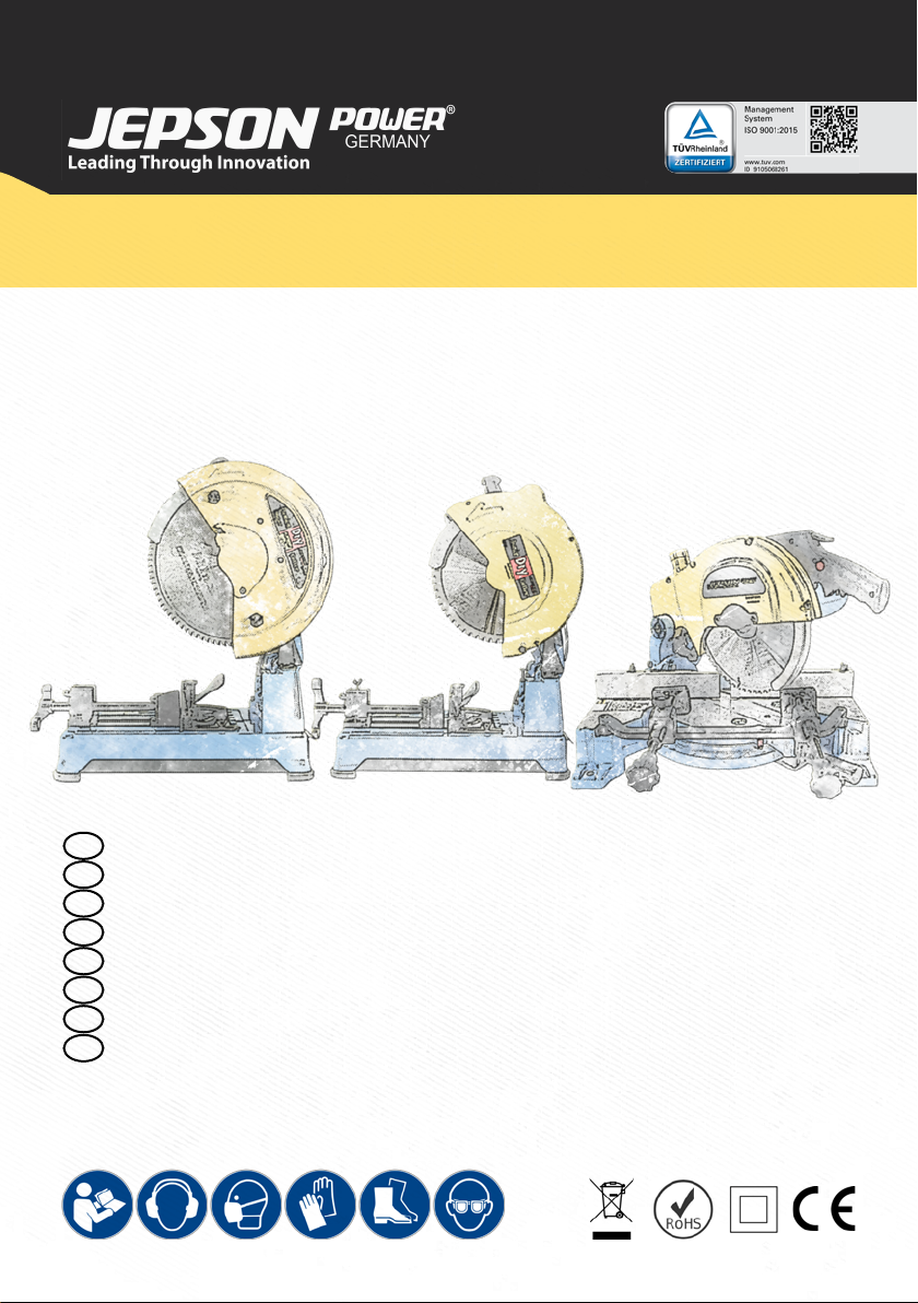
METAL CUTTING CIRCULAR SAW
PSDC 9435T3 | PDC 9430T3 | DMC 9410ND
EN METAL CUTTING CIRCULAR SAW
DE METALLKREISSÄGE
FR SCIE CIRCULAIRE A COUPE DE MÉTAL
NL METAAL CIRKELZAAG
ES SIERRA CIRCULAR PARA CORTE DE METALES
PT SERRA CIRCULAR DE CORTE DE METAL
IT SEGA CIRCOLARE PER IL TAGLIO DEI METALLI
PL PIŁA TARCZOWA DO METALU
EN Operating instructions 03 - 16
DE Betriebsanleitung 19 - 33
FR Mode d’emploi 35 - 48
NL Handleiding 51 - 64
ES Instrucciones de servicio 65 - 78
PT Instruções de utilização 79 - 92
IT Istruzioni per l’uso 93 - 106
PL Instrukcja obsługi 107 - 121
Certicates 122- 123
1 2 3
4 5 5a
67 8
910 11
12 13
A
SC
D
A
A
B
A
A
A
A
A
A
B
C
C
C
B
D
A
B
C
2

EN
DE
FR
NL
ES
PT
PL
IT
GENERAL 4
1. EC DECLARATION OF CONFORMITY PSDC 9435T3 | PDC 9430 T3 4
2. EC DECLARATION OF CONFORMITY DMC 9410ND 4
3. SHORT DESCRIPTION 5
4. TECHNICAL SPECIFICATIONS 5
5. PERFORMANCE DATA 5
6. USER INSTRUCTIONS 6
7. SAFETY INSTRUCTIONS 6
7.1. ILLUSTRATION OF SAFETY INSTRUCTIONS 6
7.2. GENERAL SAFETY INSTRUCTIONS 7
7.3. ADDITIONAL SAFETY PRECAUTIONS FOR THE PSDC9435 | PDC9430 | DMC9410ND 8
PSDC 9435 T3 | PDC 9430 T3 10
8. STARTUP 10
9. OPERATION 10
9.1. ADJUSTING THE TENSIONING DEVICE 10
9.2. POSITIONING OF THE REAR CHUCK JAW BASE FIG.1 10
9.3. WORK PIECE CLAMPING FIG.1 10
9.4. SETTING OF THE RIGHT REAR STOP FIG.3 10
9.5. QUICK RELEASE FASTENER FIG.4 10
9.6. REPLACING THE SAW BLADE 10
9.7. SAW BLADE GUIDES 11
9.8. MAINTENANCE 11
9.9. MATERIALS 11
9.10. CUTTING TECHNIQUE 11
9.11. CHIP BOX 11
9.12. TRANSPORTING THE PREMIUM SUPER DRY CUTTER 11
10. STANDARD EQUIPMENT 11
10.1. OPTIONAL SAW BLADES & ACCESSORIES PDC 9430T3 11
10.2. OPTIONAL SAW BLADES & ACCESSORIES PSDC9435T3 12
11. RECOMMENDATIONS 12
12. CORRECT CUTTING PROCEDURE AT 90° 12
DMC 9410ND 13
13. FUNCTION 13
13.1. PURPOSE 13
13.2. UNPACKING 13
13.3. FIXATION 13
13.4. FITTING THE SAW BLADE / BLADE CHANGE 13
13.5. ANGLE ADJUSTMENT FOR MITER CUT 14
13.6. SLIDING STOP 14
13.7. CLAMPING SYSTEM 14
13.8. START AND STOP THE MACHINE 14
14. MAINTENANCE AND REPAIR 15
14.1. CLEANING OF THE MACHINE 15
14.2. LUBRICATION 15
14.3. REPLACING CARBON BRUSHES: 15
15. STANDARD ACCESSORIES 15
16. RECOMMENDATIONS FOR OPTIMIZED SAW BLADE PERFORMANCE 15
GENERAL 16
17. QUOTATION 16
18. SPARE PARTS 16
19. WARRANTY 16
TABLE OF CONTENTS
3

GENERAL
1. EC DECLARATION OF CONFORMITY PSDC 9435T3 | PDC 9430T3
(according to Appendix IIA of the machine Directive)
We, Jepson Power GmbH, Ernst – Abbe – Straße 5, 52249 Eschweiler, Germany, as the manufacturer
declare herewith under our responsibility that the product:
Machine name: Metal cutting saw
Type: Premium Super Dry Cutter 9435T3 | Premium Dry Cutter 9430T3
Manufacturing date: See machine label
Serial number: See machine label
complies with the following standards, directives and referenced standard documents:
2006/42/EG Machinery Directive
2014/30/EU Electromagnetic Compatibility
2011/65/EU RoHs
EN 614-1 2006+A 1:2009 EN 55014-2 2015
EN ISO 12100 2010 EN 61000-3-2 2014
EN ISO 14120 2015 EN 61000-3-3 2013
EN 55014-1 2006+A 1:2009+A2:2011 EN 62841-1 2015
Pierre Michiels, Managing Director
Name, Position Eschweiler, 01.01.2022
2. EC DECLARATION OF CONFORMITY DMC 9410ND
(according to Appendix IIA of the machine Directive)
We, Jepson Power GmbH, Ernst – Abbe – Straße 5, 52249 Eschweiler, Germany, as the manufacturer
declare herewith under our responsibility that the product:
Machine name: Metal cutting saw
Type: Dry Miter Cutter 9410ND
Manufacturing date: See machine label
Serial number: See machine label
complies with the following standards, directives and referenced standard documents:
2006/42/EG Machinery Directive
2014/30/EU Electromagnetic Compatibility
2014/35/EU Low Voltage
EN 55014
EN 61000
EN 61029-2-4: 2011
Pierre Michiels, Managing Director
Name, Position Eschweiler, 01.01.2022
GENERAL
4

EN
DE
FR
NL
ES
PT
PL
IT
3. SHORT DESCRIPTION
The construction saws PREMIUM SUPER DRY CUTTER, PREMIUM DRY CUTTER and DRY MITER CUTTER are
designed and built according to current international standards of the machine tool industry.
The machines comply with the current regulations for emissions and safety at work, in particular the rules for
the prevention of accidents.
IMPORTANT
If changes to a machine are made without our authorisation, the certicate is null and void and the EC
conformity mark ceases to be valid. The machine may no longer be operated. Likewise, the guarantee and the
liability of the manufacturer are cancelled.
The construction saws PSDC 9435T3 | PDC 9430T3 | DMC 9410ND stand out for:
- easy transport - large work space
- simple operation - suitable for sawing metals and for mitre cuts
- many possible applications
4. TECHNICAL SPECIFICATIONS
PSDC 9435T3 PDC 9430T3 DMC 9410ND
Voltage 230 V / 50 Hz
110 V / 60 Hz
230 V / 50 Hz 230 V / 50 Hz
110 V / 60 Hz
Power input 2.400 W / 21 A (110V) 2.200 W 1.500 W / 14 A (110V)
Saw blade [mm] Ø 355 x 2,2/1,8 x 25,4 Ø 305 x 2,2/1,8 x 25,4 Ø 255 x 2,0/1,6 x 25,4
Number of teeth 90 60 60
Speed (idling) 1.400 rpm 1.400 rpm 1.600 rpm
Mitre cutting 75° - 60° - 45° 75° - 60° - 45° -45° - 0° - +45°
Surface area 480 x 290 mm 480 x 290 mm 500 x 320 mm
Weight (without saw blade) 25 kg / 56 lbs 23 kg / 51 lbs 19 kg / 42 lbs
Sound pressure level 100 db(A) 100 db(A) 100 db(A)
Sound power level 113 dB(A) 113 dB(A) 113 dB(A)
Hand and arm vibration 1,19 m/s20,53 m/s20,52 m/s2
Information referred to 2.2 of Annex 1 of the E. G. Directive on vibrations)
5. PERFORMANCE DATA
PSDC 9435T3 PDC 9430T3 DMC 9410ND
max. Ø [mm]
max a x b [mm] 90° 45° 90° 45° 90° 45°
140
125 (inox) 102 115 85 70x4 60x4
125x125 80x80 100x100 85x85 70x70x4 60x60x4
105x155 75x100 85x160 85x85 100x70x4 60x60x4
GENERAL
5

6. USER INSTRUCTIONS
Notes for the customer
The instruction manual includes important
instructions as to how to operate the machine
safely, correctly and economically. Observing
these instructions helps to avoid risks, repair costs
and downtimes and to increase the reliability and
lifetime of the machine.
The instruction manual must be read and used
by each person who works with the electrical
equipment. This applies in particular to the
“Safety Instructions” chapter. It is too late to read
the manual and safety instructions when work is
actually being carried out at the machine.
Always keep one copy of this manual next to the
machine so that it is at hand ready to be consulted!
In case of any doubt or questions, always contact
the machine manufacturer.
In addition to the instruction manual, the accident
prevention regulations which apply in the country
of use and the user location must be adhered to. In
addition, the recognised technical rules regarding
accident prevention must be observed.
Liability and warranty
All the information contained in this instruction
manual has been drawn up to the best of our
knowledge and belief, taking our experience to date
into consideration.
The original version of this instruction manual was
drawn up in the German language and was checked
by us for accuracy of content. The translation into
the respective national/contractual language was
carried out by a recognised translation agency.
This instruction manual has been put together with
the greatest of care. However, if you should discover
any incomplete items or mistakes, please inform us
in writing. Your suggestions for improvement will
help us to create a user-friendly manual.
Subsequent Orders and Copyright
Further copies of this instruction manual can be
ordered from the address below. We ask for your
understanding that further copies are subject to
charge.
Jepson Power GmbH
Ernst-Abbe-Straße 5
D-52249 Eschweiler
Phone: +49 (0)2403 – 6455-0
Fax: +49 (0)2403 – 6455-15
Mail: [email protected]
All rights are expressly reserved. Duplication or
transfer on to third parties in any form whatsoever
is not allowed without our prior written permission.
Abbreviations
V Volt
A Ampere
Hz Hertz
W Watt
~ AC
/min Revolutions per minute rpm
N Newton
7. SAFETY INSTRUCTIONS
The basic prerequisite for safe handling and
disturbance-free operation of this electric tool
is knowledge of the basic safety instructions.
In addition, the accident prevention rules and
regulations which apply in the user location must
be adhered to, as well as the recognized rules of
the trade with regard to safety and correct working
methods.
It is not permitted to use the electric tool for other
purposes than those intended by the manufacturer.
Such use could give rise to unforeseeable risks.
Local working and safety rules and laws must always
be followed. The same applies to regulations which
apply to the environment.
Safety equipment must never by removed or
bridged over.
When using oils, greases and other chemical
substances, the safety regulations which apply to
the particular product must always be observed!
Contact with chemicals should be avoided as far
as possible. Before it is permissible to work with
these substances the instructions for use on the
packaging must be read and followed. This applies
for all chemicals, therefore also for cleaning media.
All notes and signs regarding safety and possible
risks must be kept in a fully legible condition.
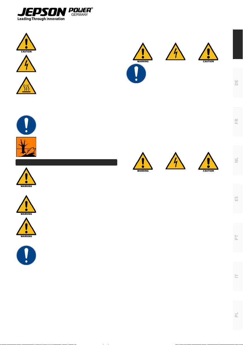
7.1. ILLUSTRATION OF SAFETY INSTRUC
TIONS
The following symbols are used in the instruction
manual:
Warning against possible danger of
injury or danger to life for persons
GENERAL
6
EN
DE
FR
NL
ES
PT
PL
IT
Warning against possible damage to
property or the environment
Warning against dangerous electrical
voltage
Warning against hot surfaces
Ignoring these instructions can lead to serious
damage to health, up to life-threatening injuries!
This symbol indicates important
information
Hazardous to the environment
7.2. GENERAL SAFETY INSTRUCTIONS
This electric tool fulls the basic EC
safety and health regulations.
Nevertheless, dangerous situations
can arise.
All safety equipment must be
maintained in perfect condition.
Always pay attention to moving
parts. These can cause injury because
of their movement or by sudden
movement.
Only use the electric tool when it is in
perfect condition from the technical
point of view, and only use it for
intended purpose while being aware
of safety issues and risks, and paying attention
to the instruction manual! In particular, have any
disturbances which could have a negative eect
on safety corrected immediately!
WARNING! It is essential to read all the
instructions. Mistakes which are made while
attempting to follow the below instructions can
cause electric shock, re and/or serious injury.
The following term “Electric tool”, refers to
mains-powered electric tools (with mains cable)
and battery-powered electric tools (without
mains cable).
KEEP THESE INSTRUCTIONS IN A
SAFE PLACE.
Work Area Safety
Keep your work area clean and well lit. Cluttered
benches and dark areas invite accidents.
Do not operate power tools in explosive
atmospheres, such as in the presence of ammable
liquid, gases, or dust. Power tools create sparks,
which may ignite the dust or fumes.
Keep bystanders, children, and visitors away while
operating a power tool. Distractions can cause you
to lose control.
Electrical Safety
Earthed tools must be plugged into an outlet
properly installed and earthed in accordance
with all codes and ordinances. Never remove the
earthing prong or modify the plug in any way. Do
not use any adaptor plugs. Check with a qualied
electrician if you are in doubt as to whether the
outlet is properly earthed. If the tools should
electrically malfunction or break down, earthing
provides a low resistance path to carry electricity
away from the user.
Avoid body contact with earthed or grounded
surfaces such as pipes, radiators, ranges and refrig-
erators. There is an increased risk of electric shock if
your body is earthed or grounded.
Don’t expose power tools to rain or wet conditions.
Water entering a power tool will increase the risk of
electric shock.
Don’t abuse the cord. Never use the cord to carry
the tools or pull the plug from an outlet. Keep cord
away from heat, oil, sharp edges or moving parts.
Replace damaged cords immediately. Damaged or
entangled cords increase the risk of electric shock.
When operating a power tool outside, only use
authorized cords for outdoor work. These cords are
rated for outdoor use and reduce the risk of electric
shock.
If operating a power tool in a damp location is
unavoidable, use an earth leakage circuit breaker.
GENERAL
7

Use of an earth leakage circuit breaker reduces the
risk of electric shock.
Personal Safety
Stay alert, watch what you are doing and use
common sense when operating a power tool. Do
not use tool while tired or under the inuence
of drugs, alcohol, or medication. A moment of
inattention while operating power tools may result
in serious personal injury.
Use safety equipment. Always wear eye protection.
Safety equipment such as dust mask, non-skid
safety shoes, hardhat, or hearing protection used for
appropriate conditions will reduce personal injuries.
Avoid accidental starting. Be sure switch is o-po-
sition before connecting to power source, picking
up or carrying the tool. Carrying tools with your
nger on the switch or plugging in tools that have
the switch on invites accidents
Remove any adjusting key or wrenches before
turning the tool on. A wrench or a key that is left
attached to a rotating part of the tool may result in
personal injury.
Do not overreach. Keep a proper footing and
balance at all times. Proper footing and balance
enables better control of the tool in unexpected
situations.
Dress properly. Do not wear loose clothing or
jewelry. Keep your hair, clothing and gloves away
from moving parts. Loose clothes, jewelry or long
hair can be caught in moving parts.
Tool use and care
Do not force the tool. Use the correct tool for your
application. The correct tool will do the job better
and safer at the rate for which it is designed.
Do not use tool if switch does not turn it on and o.
Any tool that cannot be controlled with the switch
is dangerous and must be repaired.
Disconnect the plug from the power source before
making any adjustments, changing accessories, or
storing the tool. Such preventive safety measures
reduce the risk of starting the tool accidentally.
Store idle tools out of reach of children and do not
allow persons unfamiliar with the power tool or
these instructions to operate the power tool. Tools
are dangerous in the hands of untrained users.
Maintain tools with care. Keep cutting tools sharp
and clean. Properly maintained tools, with sharp
cutting edges are less likely to bind and are easier
to control.
Check for misalignment or binding of moving parts,
breakage of parts, and any other condition that may
aect the tools operation. If damaged, have the
tool serviced before using. Poorly maintained tools
cause many accidents.
Use the power tool, accessories and blades etc.,
in accordance with these instructions and in the
manner intended for the particular type of power
tool, taking into account the working conditions
and the work to be performed. Use of the power
tool for operations dierent from those intended
could result in a hazardous situation.
Use clamps or other practical way to secure and
support the work piece to a stable platform. Holding
the work by hand against your body is unstable and
may lead to loss of control.
Use only accessories that are recommended by the
manufacturer for your model. Accessories that may
be suitable for one tool may become hazardous
when used on another tool.
Service
Only qualied repair personnel must perform
tool service. Service or maintenance performed
by unqualied personnel could result in a risk of
injury.
When servicing tool, use only identical
replacement parts. Follow instructions in
the maintenance section of this manual. Use
of unauthorized parts or failure to follow
maintenance Instructions may create a risk of
electric shock or injury.
7.3. ADDITIONAL SAFETY PRECAUTIONS
FOR THE PSDC9435 | PDC9430 | DMC9410ND
Do not use the appliance in presence of ammable
solids, liquids or gases. Sparks from the armature
assembly or the brushes can cause a re or
explosion.
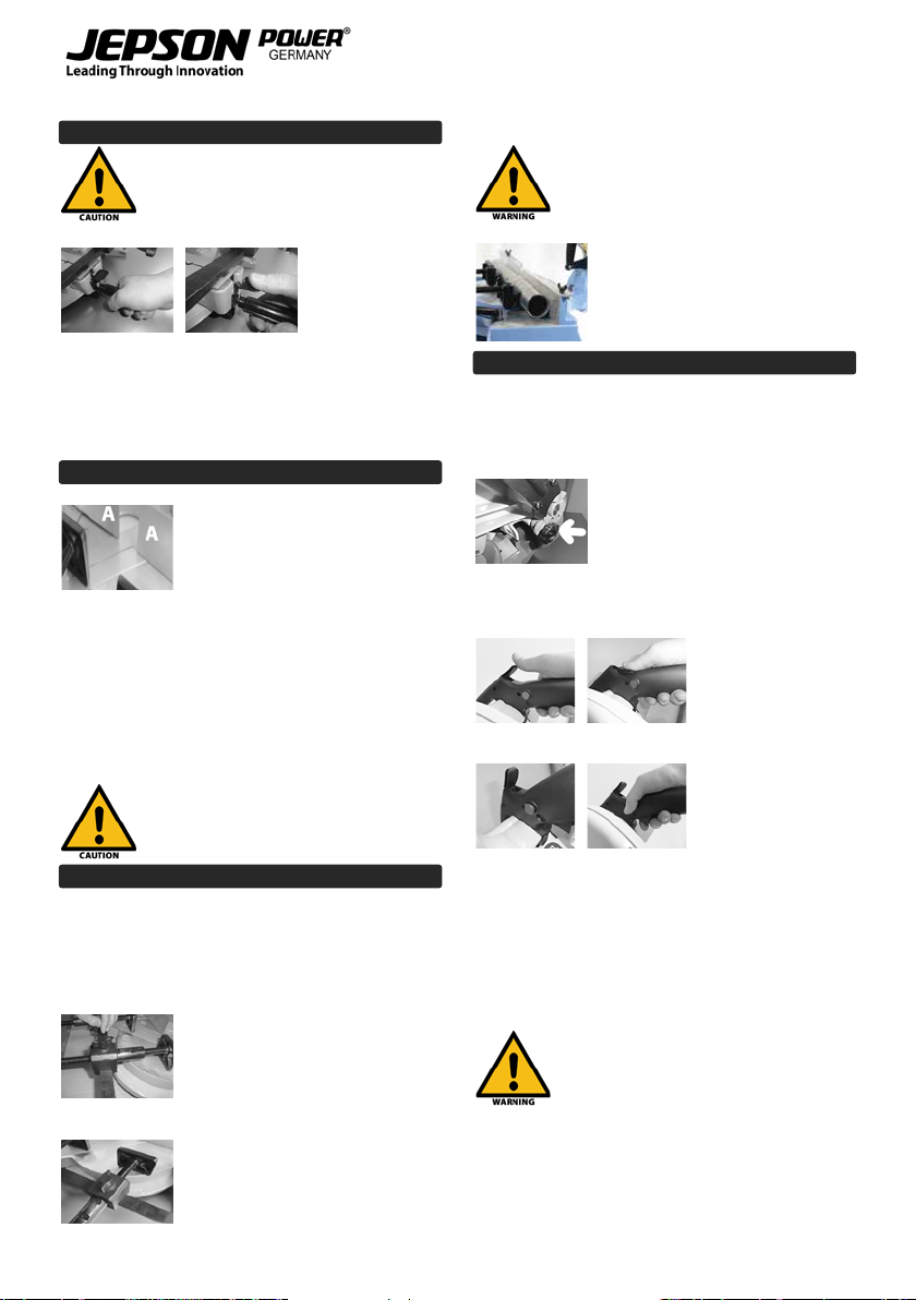
WARNING! Risk of injury from hot chips.
Never touch the blade while the
GENERAL
8
EN
DE
FR
NL
ES
PT
PL
IT
machine is running, and keep away from all the
injury-prone body parts.
Never lean on the machine. Machine can tilt and
start unexpectedly and cause serious accidents.
Damaged parts must be checked and
repaired before the machine is used.
Please check carefully the protection
cover or any other parts in case they
are damaged to determine that they are working
properly according to their function.
The adjustment of moving parts,
mounting and any other conditions that
may aect the operation of the machine
must be checked by a qualied service
technician before the machine is put into operation.
All defective parts must be properly repaired or
replaced.
Never run the machine unattended.
Don’t leave the machine before the saw blade stops.
In case of maintenance or service use only original
spare parts.
1. Workpiece has to be always xed.
2. Check the direction of rotation of the saw
blade.
3. Make sure that the blade is always sharp, as
well as unhindered and vibration free running.
4. Before actuating the safety switch, return the
machine to its default position. The saw blade
may not touch the work piece.
5. Never start cutting before you reached full
load speed.
6. Never put your hands in the work area access
if the machine is connected to the socket.
7. Protect the machine against humidity.
8. Wear Safety glasses, gloves and hearing
protection.
Keep the labels and nameplates. These contain
important information. If they are unreadable or
missing, you need to obtain a replacement.
GENERAL
9

PSDC 9435 T3 | PDC 9430 T3
8. STARTUP
After unpacking the machine from the packaging,
verify if the content is complete. Place the machine
on a surface so that it is solid and as level as
possible. Loosen the locking bolt. Install the saw
blade according to the instructions in chapter 7.2,
“Replacing the Saw Blade”. Before inserting the
power supply plug into the socket, make sure that it
is a grounded socket. In the case you are using cable
extensions, you must make sure that they are also
grounded.
9. OPERATION
9.1. ADJUSTING THE TENSIONING DEVICE
It is important for the safe operation of the circular
cold saw as well as for good cut and a long life of the
machine that the work piece is clamped securely.
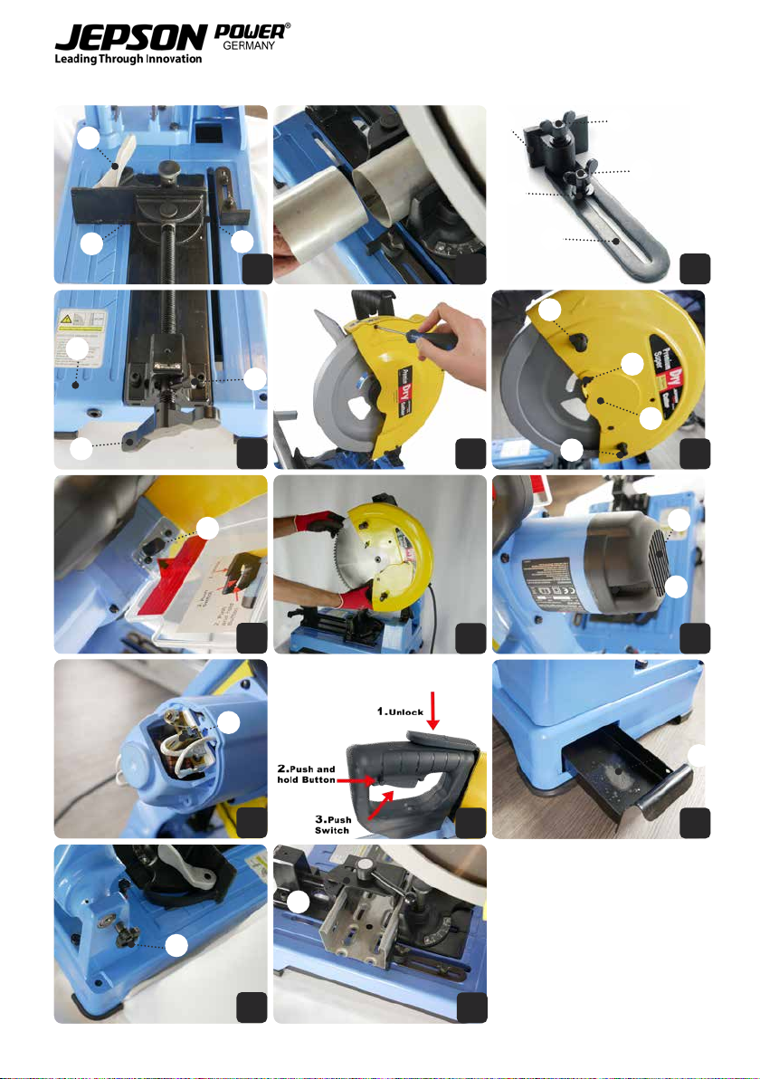
9.2. POSITIONING OF THE REAR CHUCK JAW
BASE FIG.1
The rear chuck jaw base can set to 3 positions (3
holes) to adjust it to dierent material dimensions.
Remove screw A and locking lever B for the
adjustment, position
the chuck jaw base accordingly, and then tighten
screw A and locking lever B.
For cuts at angles of 0° (90°), 15°, and 30° of materials
up to 25 mm thickness, the chuck jaw base should
be set to medium position. For thicknesses over 25
mm, set it to the rear position
9.3. WORK PIECE CLAMPING FIG.1
Put the work piece between the clamping plate
(C) and the rear chuck jaw (D) and ensure that the
tensioning device is tightened with the locking
lever (B) in clockwise direction. In order to set the
rear chuck jaw (D) of the vice to the desired angle,
loo- sen screw A and locking lever B and adjust
the desired angle. The machine is equipped with
an adjustable back support for the sawing section
(Figure 2).
9.4. SETTING OF THE RIGHT REAR STOP
FIG.3
The use of the right rear stop (stopper) extends the
service life of the saw blade and is particularly useful
in order to avoid that small sections are thrown into
the protec- tive cover.
To do so, loosen the screw C and align the right rear
stop in a straight line with the rear chuck jaw set.
Then tighten the screw C again. Depending on the
material thick- ness, insert the screw D into hole A
or B.
9.5. QUICK RELEASE FASTENER FIG.4
The quick release fastener permits quick pre-ad-
justing in order to avoid having to rotate the
clamping xture too much via the clamping handle
to bring it into position depending on the work
piece size. To do so, turn the locking pin (A) left into
a perpendicular position: You can now pre-adjust
the clamping xture (B) without screwing. After
having done this, turn the locking pin right again
so that the thread engages again. You can now
clamp the work piece tight by rotating the clamping
handle.
9.6. REPLACINGTHE SAW BLADE
The blade can be replaced easily by following these
instructions:
Step 1
Pull the power supply plug from the socket. Next,
put the plug aside so that it cannot be plugged in
accidentally.
Step 2 (Figure 5)
Premium Dry Cutter 9430: Loosen the protective
cover and push the cover to the side (Figure 5).
Premium Super Dry Cutter 9435: Loosen the
buttery screw (A), turn the small cover (B) to the
rear, pull up the vibration dampers (C), and lock
them by turning them to the side (gure 5a).
Step 3 (Figure 6 and 7)
Push in spindle lock (Figure 6-A). Grip the screw
with the hexagonal wrench and loosen the screw.
Turn the face cover up and carefully remove the
outer ange and saw blade (Figure 7).
Step 4 (Figure 7)
Push the new blade carefully onto the axle shaft,
ensuring that the rotation direction indicated on
the saw blade runs counter-clockwise and the saw
blade is grease-free. Also ensure that the blade
rotates in the direction indicated by the arrow on
the pro- tective cover. Next, replace the external
ange and the screw and tighten rmly
PSDC 9435 T3 | PDC 9430 T3
10

EN
DE
FR
NL
ES
PT
PL
IT
Step 5
Premium Dry Cutter 9430: The face cover is attached
by turning it back to its original position and
replacing the screws (Figure 5).
Premium Super Dry Cutter 9435: Turn the small
cover back to its original position and tighten the
buttery screw (Figure 5a-A). Move the vibration
dampers back to their original position by turning
them (gure 5a-C).
Step 6
Loosen the spindle lock and ensure that
the saw blade can rotate freely (Figure
6).
9.7. SAW BLADE GUIDES
Regularly spray the spots where the saw blade
comes into contact with the saw blade guides with
lubricating oil spray. Since the vibration dampers
are consumption parts, they should be replaced
when they are worn down by approx. 3 mm to a
residual value of 1 mm.
9.8. MAINTENANCE
Replacing the carbon brushes: (Figure 8 and 9)
1. Replace the carbon a brush when they are
worn down to approx. 1/4“ (6 mm) or spark
formation occurs. Both brushes must be
replaced at the same time.
2. Remove the worn brushes, insert the new
brushes and close the cover again.
The carbon brushes must be replaced
by an electrician!
9.9. MATERIALS
• Rust and acid-resistant steel (V2A) (Super Dry
Cutter)
• Mass structural steel (ST 33, ST 37-2, ST 52-3)
• Casting (SML Pipes)
• Water and gas pipes
• Angle bars, U proles and double T proles
• Plastic-encased pipes
9.10. CUTTING TECHNIQUE
Step 1: The circular cold saw can cut at angles of
45°-90°.
a) For 90°, position the work piece between the
clamping plate and the setting up piece and ensure
that the clamping xture is tightened with the
clamping handle in clockwise direction.
b) For 45°, loosen the screw at the setting up piece,
set the machine to the desired angle and re-tighten
screws.
Next, insert the work piece and tighten the
clamping xture rmly.
Step 2: On the handle, there is a safety switch
(Figure 10). In order to turn on the machine, push
the arm lock (A) simultaneously with the switch
handle (B). Only then, the handle can be moved
downwards.
Ensure that the motor runs load free for a few
seconds to reach the maximum operating speed
before you start sawing.
Step 3: Cut slowly and evenly. Lift the handle o the
work piece and release the switch to switch o the
saw. Release the handle only after the saw blade
comes to a total standstill.
9.11. CHIP BOX
The chip box (Figure 11/A) catches up to 80% of the
chips.
9.12. TRANSPORTING THE PREMIUM SUPER
DRY CUTTER
If you want to transport the Premium Super Dry
Cutter machine, keep the stopper handle (Figure
12/A) pulled outward and lower the operating arm
to the lowest position. Now let the stopper handle
engage.
You can now transport the device with the handle.
10. STANDARD EQUIPMENT
PDC 9430 T3:
1. Carbide tipped saw blade 60T
(305x1.8/2.2x25.4 mm) (Part no. 600530)
2. Hexagonal wrench and screwdriver
PSDC 9435 T3:
1. Carbide tipped saw blade 60T
(355x1.8/2.2x25.4 mm) (Part no. 600570)
2. Hexagonal wrench and jig plate
3. “K” clamping system (1209471)
10.1. OPTIONAL SAW BLADES &
ACCESSORIES PDC 9430T3
1. 80T carbide tipped saw blade for steel and
other materials (Part no. 600540)
2. 60T carbide tipped saw blade for steel and
other materials (Part no. 600530)
PSDC 9435 T3 | PDC 9430 T3
11

3. 60T carbide tipped saw blade for SML (Part no.
600535)
4. 60T carbide tipped saw blade steel and
stainless steel (Part no. 600530 40)
5. Thinx (Part no. 600546) (Figure 13)
6. Excentric clamping system (Part no. 609910)
7. Mounting stand (Part no. 600526T3)
10.2. OPTIONAL SAW BLADES &
ACCESSORIES PSDC9435T3
1. 120T carbide saw blade for very thin steel and
other materials except SML (Part no. 600512I)
2. 90T carbide saw blade for stainless steel (Part
no. 600570NSF)
3. 90T carbide saw blade for steel and other
materials except SML (Part no. 600570)
4. 72T carbide saw blade for steel and other
materials except SML (Part no. 600580)
5. 60T carbide saw blade for steel and other
materials except SML (Part no. 600590)
6. 60T carbide saw blade for SML pipes (not for
steel) (Part no. 600591)
7. 66T carbide saw blade for mass steel (not
usable for stainless steel and SML) (Part no.
600595)
8. 96T carbide saw blade for aluminum (Part no.
600594)
9. Thinx (Part no. 600546) (Figure 13)
10. Excentric clamping system (Part no. 609910)
11. Mounting stand (Part no. 600526T3)
11. RECOMMENDATIONS
In order to achieve an optimal saw blade
performance, please read the following recommen-
dations:
1. Fasten the work piece well
First check by hand if the work piece is safely
and solidly attached
- Clamp and cut pipes and round materials
individually only.
2. At the beginning insert the carbide tipped saw
blade carefully and gently into the material
and then continue sawing quickly.
3. Carefully remove chips deposited between
the carbide teeth during the work before
continuing to work.
4. Check the carbide saw blade regularly
for abrasion and broken carbide teeth.
If a blade becomes blunt due to wear and
broken teeth, replace it with a new one.
5. Always wear safety goggles when sawing.
6. Never reach into the running saw with your
hands. Keep clothing away.
7. Watch for the rotation direction when
mounting the saw blade.
8. Have saw blades sharpened only by
specialised sharpening services.
9. Saw blades can be re-sharpened 5 times on
average.
12. CORRECT CUTTING PROCEDURE AT 90°
PSDC 9435 T3 | PDC 9430 T3
12

EN
DE
FR
NL
ES
PT
PL
IT
DMC 9410ND
13. FUNCTION
13.1. PURPOSE
WARNING: The machine should not be
modied or changed, such as for a
dierent type of use, as specied in this
manual. The user is liable for any
damages or injuries caused by improper use.
The DRY MITER CUTTER 9410ND is suitable for
cutting strips, tubes and proles made of steel,
copper, brass, aluminum, plastic and composite
materials.
13.2. UNPACKING
Remove the machine and all loose parts from the
box. Keep all packaging materials until you have
checked the machine and have satised taken into
operation.
1. DRY MITER CUTTER
2. Saw blade 255/60T
3. “K” clamping system for pipes
4. Vice
5. Allen key
Start to work with the machine only after you have
read these operating instructions carefully and
understood. From the factory side already set is the
cutting depth and the pivot point (distance from
the sliding stop motor spindle) See table sliding
stop marker on the circular saw table.
For transportation
purposes, the rear
clamping jaw is
mounted in the
rearmost position. In
order to achieve the
maximum working
space of +/- 45°, the
clamping system must be adjusted. To do this,
slightly loosen the 4 screws with which the rear
clamping jaw is xed. The rear clamping jaw is then
pushed into the foremost position and xed again.
(1) (2) Note: The
machine is
delivered from
the factory with a
table insert (1).
The saw groove (2) must be made by the user with
the rst cut. The machine must be set to the 90 °
position for this.
13.3. FIXATION
For stationary use of the saw
xation holes are provided for
xing the saw, respectively two in
the front and rear area.
13.4. FITTING THE SAW BLADE / BLADE
CHANGE
Unplug from the socket.
Remove screw # 1 on saw
protection and remove protection
cover and place back.
Push the spindle lock and rotate
blade until it clicks (transmission is
blocked)
(1) (3)(2)
Blade screw with the Allen wrench in the direction
of rotation out to the right (1) Remove the ange (2)
and remove the blade. (3)
Place the new blade on the spindle and make
sure that the displayed rotation on the blade is
clockwise. Place the ange on the spindle and
tighten the Allen screw in clockwise rotation again.
Put the protection cover back in
place and tighten the screws.
WARNING: After changing of saw blade
always make absolutely sure that the
spindle lock is release to prevent any
transmission damage!
DMC 9410ND
13
13.5. ANGLE ADJUSTMENT FOR MITER CUT
Conversion to jack rafter is prohibited
on the 9410ND!
(1) (2) Put the knob a
half turn to the
left (1), with the
thumb locking
bow down (2).
The saw is now swiveled to both sides up to
45°. Adjust the desired miter angle on the scale.
For common angle precisely locating points are
available.
13.6. SLIDING STOP
The sliding stop (A) is already
exactly set to the angular
precision spindle motor by the
manufacturer. See label on the
round table (pivot). To reach even
a bigger cutting capacity, the slide
stop can pushed back by loosen the 4 Allen screws
The stopper has also displaced stop surfaces on
both sides. Advantage: for unstable and thin-walled
sections theses stopper surfaces can be adjust close
to the saw blade.
This will guarantee a clean cut and no blocking of
the saw blade by deviant back material.
Before you make the miter cut, keep
sure that the slide stop is in the correct
position. (A)
13.7. CLAMPING SYSTEM
The quick-release clamping system allows quick
pre-adjustment in order to avoid that, depending
on the workpiece size, the clamping device has
to be laboriously turned into position using the
clamping handle.
(1)
Turn the thumbscrew on (1).
(2) Pre-adjust now the tensioner
without threads in 3 dierent
positions. Fixation is done with the
threaded rod by turning the
tension handle. (1 + 2)
WARNING: Before starting the machine,
Please make sure that the material is
clamped rmly.
Article ID: 600653
Optional adapter for clamping of
round and square tubes
Ø 30mm - 70mm
13.8. START AND STOP THE MACHINE
Make sure that the mains voltage is the same as that
on the name plate of the machine indicated and
that the switch is o before you connect the device
to the mains.
Transportation lock:
The transportation lock keeps the
saw arm, and the saw head with
the blade in the lowest position.
To start the machine:
First: Press the safety
(1A) (1B) lever to release the
saw head. (1A) Start
it. Keep the saw head
down about 1 cm
(1B)
(2) (3) On the switch handle
is a safety button (2).
To start the motor,
the safety button
and the on-o switch
to be pressed simultaneously. (2 + 3)
To turn o:
Release the on / o switch (3) and security button,
than the motor is stopped.
Keep the saw head back up the saw blade guard will
automatically close and lock the saw head in its nal
position.
WARNING! Always turn o the machine
and unplug from the socket
immediately after use to prevent
accidents caused by untrained
personnel.
DMC 9410ND
14

EN
DE
FR
NL
ES
PT
PL
IT
14. MAINTENANCE AND REPAIR
14.1. CLEANING OF THE MACHINE
Blow periodically from all vents with dry
compressed air. All plastic parts should be cleaned
with a soft damp cloth. NEVER use solvents to clean
plastic. They could possibly dissolve or otherwise
damage the material. Wear safety glasses while
using compressed air.
14.2. LUBRICATION
Choose to replace the gear grease every 100 hours
by a qualied service technician.
14.3. REPLACING CARBON BRUSHES:
Replace carbon brushes when they wear down
to about 1/4 “(6mm) or sparking will occur. Both
brushes should be replaced at the same time.
Remove the brush holder caps
with a screwdriver.
Pull out the worn brushes, replace
with the new brushes and secure
the brush holder caps.
To maintain product safety and Reliability, repairs,
any other maintenance or adjustment should be
performed by Authorized Service centers, always
use original Jepson replacement parts.
15. STANDARD ACCESSORIES
• 60 T saw blade for unalloyed steel (600598)
• “K”clamping system for pipes (600653)
Optional accessories:
• 60 T saw blade for unalloyed steel (600598)
• 66T saw blade for stainless steel (600654NSF)
• 66T saw blade for thin steel(600654)
• 80T saw blade for aluminum (600655A)
• 66T IMPACT RESISTANT saw blade for gratings
and thin steel (72225566)
• Mounting stand (600599)
• “K”clamping system for pipes (600653)
16. RECOMMENDATIONS
FOR OPTIMIZED SAW BLADE
PERFORMANCE
1. Check that the workpiece is rmly xed.
2. First check by hand, if the workpiece is xed
and stable. Clamp and cut tubes and round
material only individually.
3. Second introduce at the beginning saw blade
carefully and gently into the material and
continue rapid with sawing.
4. Chips, which are deposited during the work
between the carbide teeth, remove carefully
before further work.
5. Please check the carbide tipped saw blade
regularly for wear and teeth chipping. Replace
the saw blade in case of wear or chipping by
a new one.
6. Always wear safety glasses during work.
7. Never reach with hands in the running saw.
8. Keep attention that clothes away.
9. Keep Attention by the blade assembly on the
direction of rotation.
10. Resharpen the saw blades always by profes-
sional resharpening services
11. Saw blades can be sharpened on average 5
times
DMC 9410ND
15

GENERAL
17. QUOTATION
When returning a defective machine for repair with
cost estimate. We charge a handling fee of 50€, but
does not apply if a repair order or purchase of a new
machine is given.
18. SPARE PARTS
For current spare parts list with order numbers
please visit our website:
www.drycutter.com
19. WARRANTY
The warranty time (warranty according to the
commercial code) is 12 months from the day of sale
to the end consumer.
It covers and is limited to the free replacement
of the defective parts or the free repair of defects
that are demonstrably due to the use of imperfect
materials during production or due to assembly
errors.
Incorrect use or start-up and unauthorized instal-
lations or repairs not specied in the operating
instructions void the warranty. Parts that are subject
to wear are also excluded from the warranty. We
expressly reserve the right to make decisions on
the warranty application. The warranty is void if
the device is opened by a third party. Transport
damages, maintenance work as well as damage and
malfunctions due to insucient maintenance are
not covered by the warranty.
For warranty claims, the proof of purchase of the
device must be given by presenting the delivery
note, bill, or cash receipt.
As far as it is legal, we assume no liability for any
personal, material or consequential damages, in
particular if the device is used dierently than for
the purpose indicated in the operating instructions,
not installed or repaired according to the opera-
ting instructions, or repairs were executed by a
layperson.
We reserve the right to perform repairs or
maintenance over and above the ones specied in
these operating instructions at the factory.
The warranty excludes wear parts such as:
Switches, anges, carbon brushes, supportings
and Cutting tools (saw blades, carbide inserts,
drills and abrasive).
The quality and safety of the JEPSON circular
cold saw depends on the exclusive use of original
JEPSON saw blades. The use of other saw blades
may damage the machines.
The original JEPSON saw blade fulls all
requirements of the TÜV examination (several
inspection oces) and is therefore certied by
these inspection oces. In case of use of saw blades
of foreign makes, the manufacturer assumes no
liability.
Exclusion of the JEPSON POWER warranty
The warranty excludes:
• Parts that are subject to wear through use or
natural wear and tear, as well as tool defects due
to wear and tear due to normal conditions of use
or due to natural wear and tear.
• Tool failure due to non-compliance with the
instruction manual, unconventional use,
abnormal atmospheric conditions, improper
operating conditions, overload, or lack of service
or maintenance.
• Tool failure due to replacement parts or
additional parts that are not genuine Jepson
Power parts.
• Machines to which changes or additions have
been made.
• The minor dierences from the intended use of
the device that are not material to the value and
suitability of the tool.
GENERAL
16

EN
DE
FR
NL
ES
PT
PL
IT
GENERAL
17

18

EN
DE
FR
NL
ES
PT
PL
IT
ALLGEMEINES 20
1. EGKONFORMITÄTSERKLÄRUNG PSDC 9435 T3 | PDC 9430 T3 20
2. EGKONFORMITÄTSERKLÄRUNG DMC 9410ND 20
3. KURZBESCHREIBUNG 21
4. TECHNISCHE DATEN 21
5. LEISTUNGSDATEN 21
6. BENUTZERHINWEISE 22
7. SICHERHEITSHINWEISE 22
7.1. DARSTELLUNG VON SICHERHEITSHINWEISEN 22
7.2. ALLGEMEINE SICHERHEITSHINWEISE 23
7.3. ZUSÄTZLICHE SICHERHEITSVORKEHRUNGEN FÜR DEN PSDC9435 | PDC9430 | DMC9410ND 25
PSDC 9435 T3 | PDC 9430 T3 27
8. INBETRIEBNAHME 27
9. BEDIENUNG 27
9.1. EINSTELLUNG DER SPANNVORRICHTUNG 27
9.2. POSITIONIERUNG DES HINTEREN SPANNBACKENSOCKELS ABBILDUNG 1 27
9.3. WERKSTÜCKEINSPANNUNG ABBILDUNG 1 27
9.4. EINSTELLUNG DES RECHTEN HINTERANSCHLAGS ABBILDUNG 3 27
9.5. SCHNELLSPANNVORRICHTUNG ABBILDUNG 4 27
9.6. WECHSELN DES SÄGEBLATTES 27
9.7. SÄGEBLATTFÜHRUNGEN 28
9.8. WARTUNG 28
9.9. MATERIALIEN 28
9.10. SCHNEIDVERFAHREN 28
9.11. SPÄNEBEHÄLTER 28
9.12. TRANSPORT DES PREMIUM SUPER DRY CUTTERS 28
10. STANDARDAUSRÜSTUNG 29
10.1. OPTIONALE SÄGEBLÄTTER UND ZUBEHÖR PDC 9430T3 29
10.2. OPTIONALE SÄGEBLÄTTER UND ZUBEHÖR PSDC9435T3 29
11. EMPFEHLUNGEN 29
12. RICHTIGE SCHNEIDWEISE BEI 90° 29
DMC 9410ND 30
13. FUNKTIONSBESCHREIBUNG 30
13.1. VERWENDUNGSZWECK 30
13.2. AUSPACKEN 30
13.3. FIXIERUNG 30
13.4. EINSETZEN DES SÄGEBLATTES / SÄGEBLATTWECHSEL 30
13.5. WINKELEINSTELLUNG FÜR DEN GEHRUNGSSCHNITT 31
13.6. SCHIEBEANSCHLAG 31
13.7. KLEMMSYSTEM 31
13.8. START UND STOP DES GERÄTES 31
14. WARTUNG UND REPARATUR 32
14.1. REINIGUNG DES GERÄTES 32
14.2. SCHMIERUNG 32
14.3. AUSWECHSELN DER KOHLEBÜRSTEN 32
15. STANDARDZUBEHÖR 32
16. EMPFEHLUNGEN FÜR EINE OPTIMALE SÄGEBLATTLEISTUNG 32
ALLGEMEINES 33
17. KOSTENVORANSCHLAG 33
18. ERSATZTEILE 33
19. GARANTIE 33
19
INHALTSVERZEICHNIS
ALLGEMEINES
1. EGKONFORMITÄTSERKLÄRUNG PSDC 9435 T3 | PDC 9430 T3
(nach Anhang IIA der Maschinenrichtlinie)
Wir, Jepson Power GmbH, Ernst – Abbe – Straße 5, 52249 Eschweiler, Germany, erklären in alleiniger
Verantwortung , dass das Produkt
Maschinenbezeichnung: Metallkaltkreissäge
Typ: Premium Super Dry Cutter 9435T3 | Premium Dry Cutter 9430T3
Baujahr: Siehe Maschinenetikett
Seriennummer: Siehe Maschinenetikett
Auf das sich diese Erklärung bezieht, mit den folgenden EG-Richtlinien und harmonisierten Normen oder
anderen normativen Dokumenten übereinstimmt:
2006/42/EG Machinery Directive
2014/30/EU Electromagnetic Compatibility
2011/65/EU RoHs
EN 614-1 2006+A 1:2009 EN 55014-2 2015
EN ISO 12100 2010 EN 61000-3-2 2014
EN ISO 14120 2015 EN 61000-3-3 2013
EN 55014-1 2006+A 1:2009+A2:2011 EN 62841-1 2015
Pierre Michiels, GF
Name, Position Eschweiler, 01.1.2022
2. EGKONFORMITÄTSERKLÄRUNG DMC 9410ND
(nach Anhang IIA der Maschinenrichtlinie)
Wir, Jepson Power GmbH, Ernst – Abbe – Straße 5, 52249 Eschweiler, Germany, erklären in alleiniger
Verantwortung , dass das Produkt
Maschinenbezeichnung: Metallkaltkreissäge
Typ: Dry Miter Cutter 9410ND
Baujahr: Siehe Maschinenetikett
Seriennummer: Siehe Maschinenetikett
Auf das sich diese Erklärung bezieht, mit den folgenden EG-Richtlinien und harmonisierten Normen oder
anderen normativen Dokumenten übereinstimmt:
2006/42/EG Machinery Directive
2014/30/EU Electromagnetic Compatibility
2014/35/EU Low Voltage
EN 55014
EN 61000
EN 61029-2-4: 2011
Pierre Michiels, Managing Director
Name, Position Eschweiler, 01.01.2022
20
ALLGEMEINES
Other manuals for 9435 T3
1
This manual suits for next models
2
Table of contents
Languages:
Other Jepson Saw manuals


