CH Hanson Palmgren 9683337 Instructions for use

Operating Instructions & Parts Manual EN
14” Cold Saw
230 V, 3-Phase
Model 9683337
9644410.01

PLEASE READ AND SAVE
THESE INSTRUCTIONS.
READ CAREFULLY
BEFORE ATTEMPTING
TO ASSEMBLE, INSTALL,
OPERATE OR MAINTAIN THE
PRODUCT DESCRIBED.
PROTECT YOURSELF AND
OTHERS BY OBSERVING ALL
SAFETY INFORMATION. FAILURE
TO COMPLY WITH INSTRUCTIONS
COULD RESULT IN PERSONAL
INJURY AND/OR PROPERTY
DAMAGE! RETAIN INSTRUCTIONS
FOR FUTURE REFERENCE.
PLEASE REFER TO BACK COVER
FOR INFORMATION REGARDING
PALMGREN’S WARRANTY
AND OTHER IMPORTANT
INFORMATION.
Model #: ___________________
Serial #: ___________________
Purch. Date: _______________
© 2019 Palmgren / a C.H. Hanson Brand
All Rights Reserved
3
GETTING STARTED SAFETY / SPECIFICATIONS ASSEMBLY / INSTALLATION OPERATION TROUBLESHOOTING MAINTENANCE / REPAIR
GETTING STARTED
Save this manual
You will need this manual for the safety warnings and
precautions, assembly instructions, operating and maintenance
procedures, parts lists and diagrams. Keep your invoice with this
manual. Write the invoice number on the inside of the front cover.
Keep this manual and invoice in a safe and dry place for future
reference.
Structural requirements
Make sure all supporting structures and load attaching
devices are strong enough to hold your intended loads.
If in doubt, consult a qualified structural engineer.
Electrical requirements
This saw does not come with a plug, and can be wired
to a plug or directly into the power main. Blue wire is
neutral, brown is line wire, and yellow with a green
stripe is ground.
The circuit must be configured to provide 230VAC at 10A,
3-phase, 60 Hz.
Tools needed
Standard professional mechanic’s hand tool set.
UNPACKING
Be careful not to touch overhead power
lines, piping, lighting, etc. if lifting
equipment is used. Cold Saw weighs approximately 463 lbs
(210 kg); proper tools, equipment and qualified personnel
hould be employed in all phases of unpacking and
installation.
Carton should be handled with care to avoid damage from
dropping, bumping, etc. Store and unpack carton with correct
side up. Unpack all parts from the container. Check for damage
as each piece is removed. Especially check the tubing located
at the bottom of the motor for kinks, cuts, or other damage that
would be detrimental to coolant flow. After unpacking Saw,
inspect carefully for any damage that may have occurred during
transit. Check for loose, missing or damaged parts. If any
damage or loss has occurred, claim must be filed with carrier
immediately. Check for completeness. Immediately report
missing parts to dealer.
Never use highly volatile solvents. Non
flammable solvents are recommended to
avoid possible fire hazard. Avoid getting cleaning solution
on paint as it may tend to deteriorate these finishes. Use
soap and water on painted components.
Palmgren model 9683337 14” Cold Saw is shipped complete in
one box. The saw comes assembled as one unit. Additional parts
which need to be assembled or fastened to the saw should be
located and accounted for before assembling.
IMPORTANT: Many unpainted steel surfaces have been
coated with a protectant. To ensure proper fit and operation,
remove the coating. Coating can be easily removed with mild
solvents, such as mineral spirits, and a soft cloth. Avoid getting
solution on paint or any of the rubber/plastic parts. Solvents may
deteriorate these finishes. Use soap and water on paint, plastic
or rubber components. After cleaning, cover all exposed surfaces
with a light coating of oil.
Package Contents:
Saw unit 1
Base/stand 1
Roller arm assembly 1
Trigger handle 1
Trigger handle rod 1
Depth stop rod set 1
Allen wrench set,
sizes: 3, 4, 5, 6, 12
1 ea
Open-end wrench, size 42 1
Manual 1
Unpack
After unpacking the unit, carefully inspect for any
damage that may have occurred during transit. Check
for loose, missing or damaged parts. Shipping damage claims
must be filed with the carrier.
Inspect
After unpacking the unit, carefully inspect for any
damage that may have occurred during transit. Check
for loose, missing or damaged parts. Shipping damage
claims must be filed with the carrier.
All tools should be visually inspected before use, in addition to
regular periodic maintenance inspections.
Be sure that the voltage labeled on the unit matches your power
supply.
See General Safety Instructions, Cautions and
Warnings as shown.

MAINTENANCE / REPAIR TROUBLESHOOTING OPERATION ASSEMBLY / INSTALLATION SAFETY / SPECIFICATIONS GETTING STARTED
4
SAFETY RULES
Completely read and understand this
owner’s manual before assembly or tool
operation. Read and understand the warnings shown on the
machine and in this manual. Failure to comply with all of
these warnings may cause serious injury or death.
PROPOSITION 65 WARNING: Some dust created by
using power tools contain chemicals known to the state
of California to cause cancer, birth defects or other
reproductive harm.
Some examples of these chemicals are:
• Lead from lead-based paints
• Crystalline silica from bricks and cement and other masonry
products.
• Arsenic and chromium from chemically-treated lumber.
Your risk from these exposures varies, depending on how often
you do this type of work. To reduce your exposure to these
chemicals: work in a well ventilated area and work with approved
safety equipment. Always wear an OSHA/NIOSH approved,
properly fitting face mask or respirator when using such tools.
Always follow proper operating
procedures as defined in this manual
even if you are familiar with the use of this or similar tools.
Remember that being careless for even a fraction of a
second can result in severe personal injury.
PREPARING FOR YOUR JOB
• Wear proper apparel. Do not wear loose clothing, neckties,
rings, bracelets or other jewelry which may get caught up in
moving parts of machine. Do NOT wear gloves.
• Wear protective hair covering to contain long hair.
• Wear safety shoes with non-slip soles.
• Wear safety glasses complying with United States ANSI
Z87.1. Everyday glasses have only impact resistant lenses.
They are NOT safety glasses. Use guards and eye shields.
• Wear face mask or dust mask if operation is dusty.
• Wear ANSI approved ear protection for extended operation.
• Be alert and think clearly. Never operate power tools when
tired, intoxicated or when taking medications that cause
drowsiness.
• Focus your attention completely on your work. Looking
around, careless actions and other distractions can result in
serious injury.
Preparing the work area for your job
•Keep work area clean. Cluttered work areas invite accidents.
• Do not use power tools in dangerous environments. Do not
use power tools in damp or wet locations. Do not expose
power tools to rain.
• Work area should be properly lighted.
• Proper electrical receptacle should be available for tool.
Three-prong plug should be plugged directly into properly
grounded, three-prong receptacle.
• Extension cords should have a grounding prong and the three
wires of the extension cord should be of the correct gauge.
• Keep visitors at a safe distance from work area.
• Keep children out of workplace. Make workshop childproof.
Use padlocks, master switches or remove switch keys to
prevent any unintentional use of power tools.
Maintaining your tool
• Failure to follow the guidelines in this manual can result in
serious injury.
• Disconnect the tool completely from its power supply before
performing any service, maintenance, repair or adjustments.
• Follow OSHA lock-out, tag-out procedures to prevent
accidental machine starts.
• Consult this manual for the proper use, specific maintenance,
and adjustment procedures.
• Keep tool lubricated and clean for safest operation.
• Read and understand warnings posted on the machine and
in this manual. Replace the warning labels if they become
obscured or removed. Failure to comply with all of these
warnings can result in serious injury.
• Before using the machine, check for damaged parts. Check
for alignment of moving parts, binding, breakage, mounting
issues and any other conditions that may affect operation.
• A guard or other part that is damaged should be properly
repaired or replaced. Do not perform makeshift repairs.
(Use parts list provided to order repair parts.)
• Use compressed air or a suitable brush to clear chips or
debris — do not use your hands.
• Remove adjusting tools. Form habit of checking to see that
adjusting tools are removed before switching machine on.

5
GETTING STARTED SAFETY / SPECIFICATIONS ASSEMBLY / INSTALLATION OPERATION TROUBLESHOOTING MAINTENANCE / REPAIR
Know how to use your tool
The operation of any tool can result in
foreign objects being thrown into the
eyes, which can result in severe eye damage. Always wear
safety goggles complying with United States ANSI Z87.1.
before commencing power tool operation.
Think safety! Safety is a combination of operator
common sense and alertness at all times when tool
is being used.
• Use right tool for job. Do not force tool or attachment to do a
job for which it was not designed.
• Disconnect tool when changing the blade.
• Avoid accidental start-up. Make sure that the tool power
switch is in the OFF position before plugging in.
• Do not force tool. It will work most efficiently at the rate for
which it was designed.
• Keep hands away from moving parts and cutting surfaces.
• Never leave tool running unattended. Turn the power off and
do not leave tool until it comes to a complete stop.
• Do not overreach. Keep proper footing and balance.
• Never stand on tool. Serious injury could occur if tool is tipped
or if blade is unintentionally contacted.
• Know your tool. Learn the tool’s operation, application and
specific limitations.
• Use recommended accessories. Use of improper accessories
may cause risk of injury to persons.
• Handle workpiece correctly. Protect hands from possible
injury.
• Turn machine off if it jams. Blade jams when it digs too deeply
into workpiece. (Motor force keeps it stuck in the work.) Do
not remove jammed or cut off pieces until the saw is turned
off, unplugged and the blade has stopped.
• Adjust upper guide to just clear workpiece.
• Hold workpiece firmly against vise.
• DIRECTION OF FEED: Feed work into a blade or cutter
against the direction of rotation of the blade or cutter only
SPECIFICATIONS
The saw features a solid cast iron vise to ensure durability. The
saw is equipped with a miter gauge for performing many different
operations.
Parameter 9683337
Description 14” Cold Saw
Blade diameter 14 in 355.6 mm
Blade thickness 0.112” 3mm
Arbor diameter 1.26in 32mm
Blade speed 40/80 rpm
Machine dimensions 54” x 55” x 77”
Base footprint 22” x 22”
Max vise opening 6”
Miter angle range 90°
Cutting angle 45° Right - 45° Left
Vise height from floor 41”
Motor specs 3HP; 10A; 3~; 230V
Motor RPM 1400 - 2800
Coolant tank capacity 0.75 Gal 3 liters
Machine weight 463 lbs 210 kg

MAINTENANCE / REPAIR TROUBLESHOOTING OPERATION ASSEMBLY / INSTALLATION SAFETY / SPECIFICATIONS GETTING STARTED
6
ASSEMBLY/INSTALLATION
Location
The saw must be installed on a structurally stable surface.
The coolant pump ouput and inputs may extend below the
coolant tank of the saw, when the saw is at rest. So ensure that
the surface the saw is installed, does not restrict the coolant
flow. Alternatively, the saw’s rest position may be adjusted by
changing the set bolt’s height.
Machine dimensions
The following figure shows the approximate dimensions of the
saw and its parts. When determining a final location for your
machine, ensure there is enough clearance for both the operator
and for technicians who will service the machine. Also,consider
the size of large workpieces that may extend beyond the
machine’s table and require extra space.
68.7”
33.3”
26.6”
28.5”
22”
37.8”
38.7”
54.4”
39.6”
44.3”
10.2”
19.7”
20.5”
20.5”
Lifting and setting up the saw
Make certain that slings, cables, chains,
forklifts or other load suspending gear or
machines used to move this saw are properly rated to
handle the weight. The saw is heavy.
The saw must be properly secured and
anchored before use. Make sure that it is
supported equally on all four corners.
1. Remove any crating or overpacking materials which may be
covering the machine. Leave the machine attached to the
pallet.
NOTE: The saw is heavy, see “SPECIFICATIONS” Be certain
any machine or devices used to lift the saw are capable
of handling this weight. If manually lifting, ensure that
enough people are performing the lift.
2. Ensure sufficient space is available for operation. See
Machine Dimensions.
3. Remove all the nuts and/or bolts securing saw to the pallet.
4. Use a forklift or an overhead crane, or other suitable
overhead lifting device and sling arrangement, centered over
the frame as shown in the following figure.

7
GETTING STARTED SAFETY / SPECIFICATIONS ASSEMBLY / INSTALLATION OPERATION TROUBLESHOOTING MAINTENANCE / REPAIR
5. Carefully lift the saw off the pallet. Lift it no higher than
necessary to clear the surface on which it is to be installed
and pull the pallet out of the way. DO NOT put your hands or
feet beneath the saw while moving it or removing the pallet.
6. Place the saw into its final location.
7. Level the saw using shims under the corners needing
them. A highly accurate spirit or digital level should used for
leveling. It is very important that the saw be properly leveled
for accurate performance.
Electrical Connection To The Mains
NOTE: Install a differential thermomagnetic switch with
characteristics suited to the mains.
This saw does not come with a plug, and can be wired to a plug
or directly into the power main. The ground wire is yellow with
a green stripe. After wiring, check that saw blade spins in the
correct direction as noted by the large arrow on the guard.
See “Parts List” on page 14 for all parts.
Assembly: Handle
1. Slide the handle (item #24) onto shaft (item #25), and screw
nut (item #50) onto the other end.
2. Screw the assembly of items 24, 25, and 50 into the top of
the saw, as shown below.
3. Tighten the set screw, found in the handle, to lock handle to
shaft.
4. The nut on the end of the rod can be used to lock the whole
handle’s rod to face the desired direction.
Depth stop
5. Slide long bar stopper rod into bar stopper, and tighten the
handle screw.
6. Position and screw into the side of the white base of the saw.
as shown in the following figure.
7. Use provided nut to lock the bar stopper in the upright
position.
Saw Blade
Select the appropriate blade for the job as shown in “Blade
Selection” on page 10.
To install the blade, remove the screw (33), keeping the motor-
blade block raised and rotate the mobile guard (31) backward.
Unscrew the screw (29) counterclockwise, withdraw the flange
(28), and insert the circular blade, making sure that the teeth face
the same direction as the arrow on the mobile guard. Then refit
flange (28) and screw (29).
Cutting Coolant
For cooling of the circular blade, fill the tank with coolant
consisting of a mixture of water and AGIP AQUAMET 700 EP oil
with a percentage of 5-7%.
Lubrication
Do not operate this saw before adding
lubricant and ensuring proper oil level.
Failure to comply may damage the saw.
For the coolant mix, use water with recommended AGIP Aquamet
700 EP oil, 5%-7%.

TROUBLESHOOTING OPERATION ASSEMBLY / INSTALLATION SAFETY / SPECIFICATIONS GETTING STARTED
8
MAINTENANCE / REPAIR
OPERATION
Always wear safety glasses complying
with U.S. ANSI Z87.1 before beginning any
power tool operation.
To avoid injury from unexpected starting,
whenever changing the saw blade or
carrying out adjustments, switch the saw off and remove the
power cord from the mains outlet. To avoid injury to hands
when handling the saw blade, wear gloves whenever
necessary.
Do not operate before properly lubricating
the saw. Failure to lubricate before using
can damage the saw.
Cutting
Power at the main power switch must be
set to “O” (OFF) .
Do not activate the saw if bolt (52) is not
tightened.
Checks to carry out before each cut:
1. Verify that a suitable blade for the material to be cut is
securely installed and that screw 28 is tight. (See ”Blade
Selection” on page 10. and “Parts List” on page 14.)
If required, replace the blade as discussed in “” on page
89.
2. Verify the cutting angle. If required, set the cutting angle
before cutting by placing the bench lever in its release
position, rotating the saw until the appropriate angle is
indicated by the angulation gauge, and forcefully pushing the
bench lever to its lock position.
Bench lever
in release
position
Angulation
gauge
To
lock position
3. With the motor off , lower the head and check that at the end
of the stroke , the circular blade does not touch the counter-
vice (75) . If the circular blade does touch , adjust the screw
(109) located at the center of the head support (4) (see
“Parts List” on page 14).
4. Clamp the piece to be cut by means of the handwheel (11,
see “Parts List” on page 14), turn the speed switch (203)
to the position required (No. 1 is recommended), grasp the
handle (26) located at the end of the head lever and press
button (218). The blade will now start turning.
5. Make sure that the coolant is circulating in the machine .
6. Without touching the micro switch, verify that the material to
be cut is positioned as required by lowering the blade to the
material. If everything is properly set, return to start position,
otherwise adjust as required.
7. If required, to make a series of cuts of the same length,
position the bar-stop (77) as required. Fix it into position
using the knob (79, see “Parts List” on page 14) .
Cutting operation:
8. To prepare the saw to cut, flip the main power rotary switch
from the “O” OFF, position to the “1” ON, position (See the
following figure). This provides power to the microswitch that
must be pressed to spin the saw blade in the next step.
Speed switch Emergency stop button
Main power switch
9. Press and hold the micro switch 218 (see “Parts List” on
page 14) located on the top handle, and the saw blade will
begin to spin. Use the handle to slowly lower the blade into
the stock to make the cut. If the micro switch is released the
saw blade will stop rotating.

9
GETTING STARTED SAFETY / SPECIFICATIONS ASSEMBLY / INSTALLATION OPERATION TROUBLESHOOTING MAINTENANCE / REPAIR
CHANGING BLADES
To remove and replace the saw blade:
1. Make sure the cold saw is disconnected from the power.
2. Hold the saw blade still, by lowering the blade into a piece of
wood set in the vise.
3. Unhook the guard rod (A) from the guard.
Blade
Guard
Blade Housing
A
B
4. Remove Allen head screw (B).
5. Use gloves to safely remove the saw blade.
6. Follow these steps in the reverse order to install a new
blade.
NOTE: The new blade will need to be broken in before full use.

TROUBLESHOOTING OPERATION ASSEMBLY / INSTALLATION SAFETY / SPECIFICATIONS GETTING STARTED
10
MAINTENANCE / REPAIR
BLADE SELECTION
NOTE: Best performance of worm screw worm wheel gearing is guaranteed when circular saw blades with drawing-holes are used.
Cutting Capcity (values in parentheses are in mm)
Cut
90º 1.18” (30) 2.56” (65) 2.17” x 2.17” (55 x 55) 1.77” x 2.76” (45 x 70)
45º 1.18” (30) 2.36” (60) 1.97” x 1.97” (50 x 50) 1.57” x 2.36” (40 X 60)
Blade Selection (values in parentheses are in mm)
Diameter 7.78” (200) 8.86” (225) 9.84” (250) 10.83” (275) 11.81” (300) 12.40” (315) 13.78” (350)
Thickness 0.07” (1.8) 0.07” (1.8) 0.08” (2) 0.10” (2.5) 0.10” (2.5) 0.10” (2.5) 0.12” (3)
b=0.39”-3.15”
(10-80)
g<(2)
t 0.12” (3) 0.12” (3) 0.12” (3) 0.12” (3) 0.12” (3) 0.12” (3) 0.12” (3)
z 7.87” (200) 9.06” (230) 9.84” (250) 11.02” (280) 11.81” (300) 12.60” (320) 13.78” (350)
b= 0.39”-3.15”
(10-80)
g=0.08”-0.16”
(2-4)
d=0.39”-0.71”
(10-18)
t 0.20” (5) 0.20” (5) 0.20” (5) 0.20” (5) 0.20” (5) 0.20” (5) 0.20” (5)
z 5.12” (130) 5.51” (140) 6.30” (160) 6.70” (170) 7.48” (190) 7.87” (200) 8.66” (220)
b= 0.39”-3.15”
(20-80)
g=0.16”-0.39”
(4-10)
d=0.71”-1.18”
(18-30)
t 0.31” (8) 0.31” (8) 0.31” (8) 0.31” (8) 0.31” (8) 0.31” (8) 0.31” (8)
z 3.15” (80) 7.48” (90) 3.94” (100) 4.33” (110) 4.72” (120) 4.72” (120) 5.51” (140)
d=1.18”-1.57”
(30-40)
t 0.39” (10) 0.39” (10) 0.39” (10) 0.39” (10) 0.39” (10) 0.39” (10) 0.39” (10)
z 2.36” (60) 2.76” (70) 3.15” (80) 7.48” (90) 7.48” (90) 3.94” (100) 4.33” (110)
d>1.57” (40) t 0.47” (12) 0.47” (12) 0.47” (12) 0.47” (12)
z 2.76” (70) 3.15” (80) 3.15” (80) 7.48” (90)
NOTE: t = tothing pitch, z = number of teeth

11
GETTING STARTED SAFETY / SPECIFICATIONS ASSEMBLY / INSTALLATION OPERATION TROUBLESHOOTING MAINTENANCE / REPAIR
TROUBLESHOOTING GUIDE
Symptom Possible Cause(s) Corrective Action
Teeth breaking Coolant flow problem Ensure proper coolant flow; hoses unclogged; nozzles pointed
correctly, etc. Make sure coolant type is suitable for the saw.
Material too hard Check the blade speed and the type of blade you are using.
Also be aware of feed pressure.
Blade not worn-in correctly With a new blade it is necessary to start cutting at half feeding
speed. After the wearing-in period (a cutting surface of about
300 cm2for hard materials and about 1000 cm2for soft
materials) the blade and feed speeds can be raised to normal
values.
Blade with excessively fine tooth pitch The swarf wedges into the bottom of the teeth causing
excessive pressure on the teeth themselves. Use a blade with
coarser tooth pitch.
New blade inserted in a partially
completed cut
The surface of the cut may have undergone work hardening.
When starting work again, use a lower blade speed and
reduced feed pressure. A tooth from the old blade may be left
in the cut: check and remove before starting work again.
Work piece not clamped firmly in place Any movement of the work piece during cutting can cause
broken teeth: check the vise, jaws and clamping pressure.
Rapid tooth wear Feed speed too slow The blade runs over the material without removing it: increase
feed speed.
Blade speed too high The teeth slide over the material without cutting it: reduce the
blade speed.
Insufficient coolant Check the coolant level and clean coolant lines and nozzles.
Incorrect fluid concentration Check and use the correct concentration.
Material defective The materials may present altered zones either on the
surface, such as oxides or sand, or in section, such as under-
cooled inclusions. These zones, which are much harder than
the blade, cause the teeth to break: Discard or clean these
materials.
Broken blade Blade speed too high Reduce blade speed.
Teeth in contact with material before
starting the cut
Always check the position of the blade before starting a new
job.
Insufficient coolant Check the coolant level and clean coolant lines and nozzles.
Cuts not straight Feed speed too high Reduce feed speed.
Blade not perpendicular to workpiece. Adjust blade tracking according to instructions. If this proves
unsuccessful, contact Palmgren technical support.
Green pilot lamp not
lit when ON button
pressed
No incoming power Check connections at machine and power source.
Lamp fuse or bulb is out Replace fuse/bulb.

MAINTENANCE / REPAIR TROUBLESHOOTING OPERATION ASSEMBLY / INSTALLATION SAFETY / SPECIFICATIONS GETTING STARTED
12
Symptom Possible Cause(s) Corrective Action
Motor will not turn Emergency stop engaged Rotate Emergency Stop button to disengage.
Electrical power supply Check: the phases; the cables; the plug; the socket. Also
check that the motor connections are in place.
Trigger switch not activating Check that socket/plug connection from handle to motor is
inserted correctly; check micro-switch in trigger.
Transformer Check that the voltages are present both on the input and
output. Otherwise replace.
Magnetic contactor Check that the phases in it are present both on the input and
output, that it is not jammed, that it closes when powered and
that it is not causing short circuits. Change if any of these
problems are found.
Thermal relay Make sure it is closed, i.e. check that the phases are present
in input and output, that it is not causing short circuits and
responds when the reset coil is closed. If it has tripped to
protect the motor, check the amperage setting, reset, and
check the motor. Change if necessary.
Motor Check that it has not burned out, that it turns freely and that
there is no moisture in the connection terminal board box. The
winding can be rewound or replaced by experienced motor
repair personnel.

GETTING STARTED SAFETY / SPECIFICATIONS ASSEMBLY / INSTALLATION OPERATION TROUBLESHOOTING MAINTENANCE / REPAIR
13
MAINTENANCE/REPAIR
Replacement of gear box oil
Place a container, labeled to indicate the contents for the
purposes of disposal, beneath cap 22. Remove caps 95 and 22
(see “Parts List” on page 14), and let the used oil drain into
the container . Replace cap 22. Pour 0.2 liters of oil (as specified
above) into the oil feed hole located on the upper part of the gear
box and then replace cap 95.
Lubrication of mobile parts of piece locking vise
Remove the vise (21) completely by turning hand wheel 11 (see
“Parts List” on page 14) . Clean and grease the parts worked
by the counter-vice 75, the vice 21 and the vice gib 101. Put a
drop of oil in the oil feed hole 19 located behind the handwheel .
Then install the vise.
Cleaning of the coolant tank : Filter check .
The coolant tank can be cleaned by simply removing the crucible
87 (see “Parts List” on page 14). Empty the coolant from the
tank and collect the coolant in a container for future disposal .
Clean away the shavings and the metallic powder , taking care
not to scatter this over the machine especially around the motor
and the box containing the electrical equipment .
Fill the tank with the 0.75 gal (3 liters) of coolant liquid:
water and 5-7% AGIP AQUAMET 700 EP oil .
Checking of bench lever functioning
Check regularly that the rotation release - locking lever is working
properly. If the lever does not lock correctly, loosen grub screw 91
(see “Parts List” on page 14), tighten nut 90 and tighten grub
screw 91 again. Make sure that with the bench lever in position 2,
arm 4 supporting the blade motor block can rotate freely .
Suggested Maintenance Schedule
FREQUENCY ( working hours ) OPERATION
1000 hrs or monthly Replace the oil in the gear box with AGIP BLASIA 220 oil (0.2 litres) or equivalent.
1000 hrs or monthly Lubricate mobile parts in the piece locking vice.
50 hrs or every 2 days Clean coolant tank and check filter.

MAINTENANCE / REPAIR TROUBLESHOOTING OPERATION ASSEMBLY / INSTALLATION SAFETY / SPECIFICATIONS GETTING STARTED
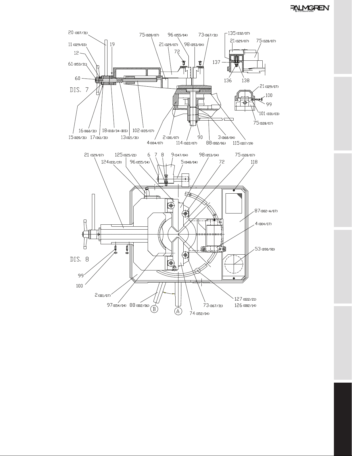
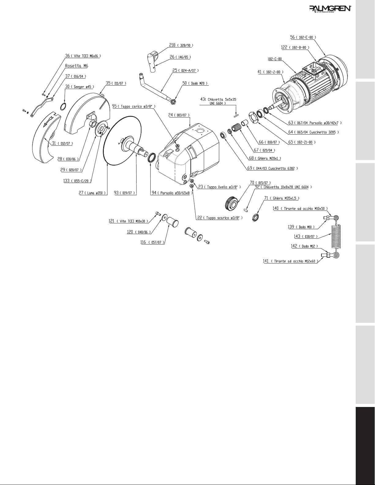
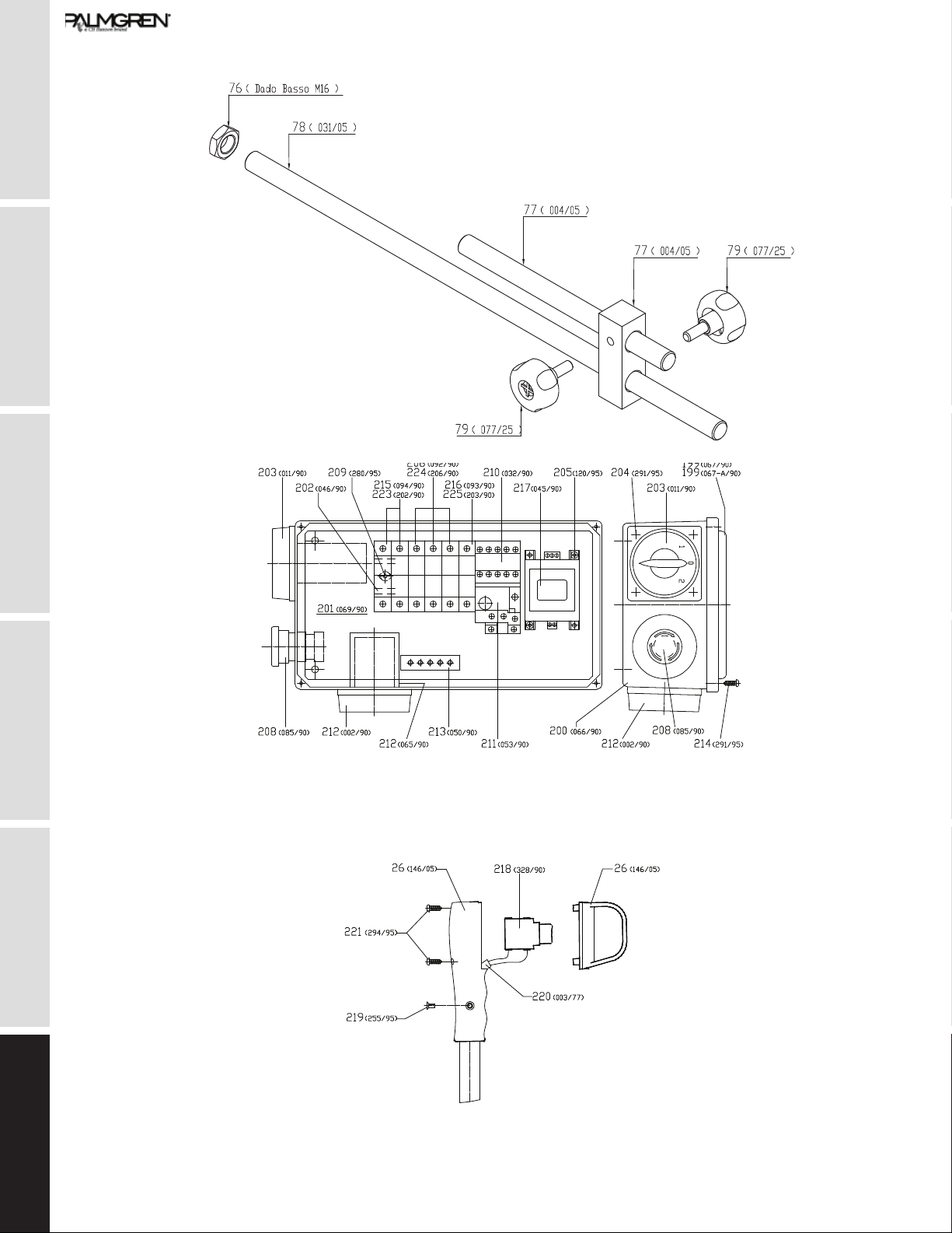
14
Parts List
GETTING STARTED SAFETY / SPECIFICATIONS ASSEMBLY / INSTALLATION OPERATION TROUBLESHOOTING MAINTENANCE / REPAIR
15

MAINTENANCE / REPAIR TROUBLESHOOTING OPERATION ASSEMBLY / INSTALLATION SAFETY / SPECIFICATIONS GETTING STARTED
16
GETTING STARTED SAFETY / SPECIFICATIONS ASSEMBLY / INSTALLATION OPERATION TROUBLESHOOTING MAINTENANCE / REPAIR
17
MAINTENANCE / REPAIR TROUBLESHOOTING OPERATION ASSEMBLY / INSTALLATION SAFETY / SPECIFICATIONS GETTING STARTED
18

GETTING STARTED SAFETY / SPECIFICATIONS ASSEMBLY / INSTALLATION OPERATION TROUBLESHOOTING MAINTENANCE / REPAIR
19
POS. DESCRIPTION Part
number
Qty
1 Pedestal 9644327.01 1
2 Base N/A 1
3 O-Ring 134 9644328.01 1
4 Rotating arm 9644329.01 1
5 Roller arm pin 9644330.01 1
6 Snap ring ø25 DIN-471 * 1
7 Nut M10 DIN-934 * 1
8 Screw HH M10x55 DIN-934 * 1
9 Roller arm 9644331.01 1
10 Roller 9644332.01 1
11 Vice hand-wheel 9644333.01 1
12 Hexagon socket grub with cone
point M8x10 DIN-914
* 1
13 Vice spring 9644334.01 1
14 Motor Assembly 9644408.01 1
15 Vice bearing flange 9644335.01 1
16 Cage AxK 30 47 9644336.01 1
17 Fifth wheel AS 30 47 9644337.01 2
18 Flanged bushing with spiral 9644338.01 1
19 Oiler ø6 9644339.01 1
20 Vice lever 9644340.01 1
21 Vice 9644341.01 1
22 Oil dram plug ø3/8” 9644342.01 1
23 Oil lever plug ø3/8” 9644343.01 1
24 Head N/A 1
25 Head lever 9644344.01 1
26 Head lever handle 9644345.01 1
27 Disk 9644346.01 1
28 Disk nut 9644347.01 1
29 Disk flange 9644348.01 1
30 Snap ring ø45 E * 1
31 Disk movable guard 9644349.01 1
32 HSHC screw M6x14 DIN-912 * 1
33 Divider 9644350.01 1
34
35 Disk guard 9644351.01 1
36 HSHC screw M6x16 DIN-912 * 2
37 Movable blade cover rod 9644352.01 1
38 HSHC screw M8x20 DIN-912 * 2
39 Fixed blade cover rod 9644353.01 1
40 Dowel M10x45 DIN-914 * 1
41 Front motor flange See Pos. 14 1
42 Motor See Pos. 14 1
43 Key 5x5x35 DIN-6604 * 1
44 Bearing 6205 2Z See Pos. 14 1
POS. DESCRIPTION Part
number
Qty
45
46
47
48
49
50 Hexagon lock nut M20 DIN-
936
* 1
51
52
53 Electric pump 9644354.01 1
54
55 No return valve 9644355.01 1
56 Fan guard See Pos. 14 1
57 Fan See Pos. 14 1
58 Rotor See Pos. 14 1
59 Stator See Pos. 14 1
60 HSFHC Screw M8x30 DIN-
7991
* 1
61 Wascher 9644356.01 1
62 Cutting angle device 9644357.01 1
63 Oil retainer 30-42-7 See Pos. 14 1
64 Bearing 3205 See Pos. 14 1
65 Bearing lid See Pos. 14 1
66 Worm screw spacer See Pos. 14 1
67 Worm screw See Pos. 14 1
68 Self-locking ring-nut M20x1 See Pos. 14 1
69 Bearing 6302 See Pos. 14 1
70 Helical gear 9644358.01 1
71 Self-locking ring-nut M35x1,5 * 1
72 HSFHC Screw M10x25 DIN-
7991
* 4
73 Washer * 4
74 Counter-vice right jaw 9644359.01 1
75 Counter-vice 9644360.01 1
76 Nut M16 DIN-936 * 1
77 Bar stop 9644361.01 1
78 Bar stopping rod 9644362.01 1
79 Bar stoppin hand-wheel 9644363.01 1
80
81
82
83
84
85
86
87 Crucible 9644364.01 1
88 Bench lever 9644365.01 1

MAINTENANCE / REPAIR TROUBLESHOOTING OPERATION ASSEMBLY / INSTALLATION SAFETY / SPECIFICATIONS GETTING STARTED
20
POS. DESCRIPTION Part
number
Qty
89
90 Selflocking ring nut M32x1.5 * 1
91
92 Key 10x8x28 DIN-6604 * 1
93 Disk shaft 9644366.01 1
94 Oil retainer 50/65x8 9644367.01 1
95 Oil filling cap ø3/8” 9644368.01 1
96 Left vice jaw 9644369.01 1
97 Right vice jaw 9644370.01 1
98 Left countervice jaw 9644371.01 1
99 Dowel M8x25 DIN-914 9644372.01 1
100 Nut M8 DIN-934 * 1
101 Vice gib 9644373.01 1
102 Fast clamping vice screw 9644374.01 1
103 Support plate of low voltage
control
9644375.01 1
104
105
106
107
108 Nut M12 DIN-936 * 1
109 HH screw M12x30 DIN-933 * 1
110 Hexagon socket grub screw
M8x10 DIN-914
* 1
111 Head gasket 9644376.01 1
112
113
114 Countervice pin 9644377.01 1
115 Rotating plate 9644378.01 1
116 Head pin 9644379.01 1
117 Oiler ø6 9644380.01 1
118 HSHC screw M6x60 DIN-912 * 1
119 HSCH screw M8x20 DIN-912 * 1
120 Washer * 1
121 HSHC screw M10x20 DIN-912 * 1
122 Rear motor flange See Pos. 14 1
123 Washer * 1
124 Countervice fastening bracket 9644381.01 1
125 Handle Jaccard M8x20 9644382.01 1
126 Sphere ø30 FM10 9644383.01 1
127 Positioning pin 9644384.01 1
128 Hexagon lock nut M10 DIN-
936
* 1
129
130 HH screw M12x80 DIN-933 * 1
131
132 Washer x M6 DIN-125/A * 1
POS. DESCRIPTION Part
number
Qty
133 Stake ø9x18 9644385.01 1
134
135 Vice bush 9644386.01 1
136 Grub screw M10x50 * 1
137 Washer for M10 * 1
138 Self locking nut M10 * 1
139 Nut M10 DIN-934 * 1
140 Eye tie rod M10x50 9644387.01 1
141 Eye tie rod M12x50 9644388.01 1
142 Nut M12 DIN-934 * 1
143 Return spring 9644389.01 1
199 Cover box 9644390.01 1
Box gasket 9644391.01 1
200 Box 9644392.01 1
201 Plate 9644393.01 1
202 Omega raceway 9644394.01 1
203 Changeover switch 9644395.01 1
204 RH screw M4x14 DIN-84-A * 1
205 HSHC screw M4x6 DIN-912 * 1
206 Fuse blok PCH 3x38 9644396.01 1
207
208 Emergency button 9644397.01 1
209 TBEI screw M4x6 ISO-7380 * 1
210 Remote controlled switch 9644398.01 1
211 Thermal relay 9644399.01 1
212 Main switch 9644400.01 1
213 Earth connection bar 9644401.01 1
214 RH screw M4,2x13 DIN-7981 * 1
215 Fuse blok PCH 2x38 9644402.01 1
216 Fuse blok PCH 1x38 9644403.01 1
217 Transformer 30 VA 0-230-
400V 50Hz
9644404.01 1
218 Micro switch of handle 9644405.01 1
219 HSFHC screw M4x8 DIN-7991 * 1
220 Electrical cable 2x1 9644406.01 1
221 RH screw M2,9x13 DIN-7981 * 1
222
223 Fuse 10x38 AM 10A * 1
224 Fuse 10x38 gG 1A * 1
225 Fuse 10x38 gG 2A * 1
Table of contents
Other CH Hanson Saw manuals


