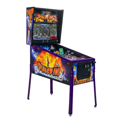
Jersey Jack Pinball The Hobbit User manual

November 2018
70-0002-00
Jersey Jack Pinball®, 1645 Oak Street, Lakewood, New Jersey 08701 Telephone: (732) 364-9900
Operations Manual Includes:
Game Setup - Testing & Adjustments - Parts Information - Reference Diagrams & Schematics - Service & Troubleshooting
© Warner Bros. Entertainment Inc. All rights reserved. THE HOBBIT: AN UNEXPECTED JOURNEY, THE HOBBIT: THE DESOLATION OF SMAUG, THE HOBBIT: THE BATTLE OF THE FIVE ARMIES
and the names of the characters, items, events and places therein are trademarks of The Saul Zaentz Company d/b/a Middle-earth Enterprises under license to New Line Productions, Inc. (s14)


Informaon current at me of release (3.0).
Visit our customer support website, hps://www.jerseyjackpinball.com/support/, and register your game.
Be sure to include the game serial number. For your records, write the game serial number in the manual.
Serial Number
Jersey Jack Pinball® reserves the rights to make modicaons and improvements to its products.
The specicaons and parts idened in this manual are subject to change without noce.
Manual Release 3.4


Table of Contents i
Table of Contents
Secon A - Game Assembly & Setup
A.1 Unpacking Your Hobbit Game
Unboxing Game ..................................................................................................................................................................................................................... A-2
Removing Playeld Glass ....................................................................................................................................................................................................... A-7
Playeld Posions .................................................................................................................................................................................................................. A-8
A.2 Hobbit Rules & Shot Maps
Skill Shots ............................................................................................................................................................................................................................... A-11
Smaug™ Mulball ..................................................................................................................................................................................................................A-12
Beast Mulball ....................................................................................................................................................................................................................... A-13
Modes - Qualifying ................................................................................................................................................................................................................A-14
Modes - Selecng ..................................................................................................................................................................................................................A-15
Modes - Beginning & Playing .................................................................................................................................................................................................A-16
Other Game Objecves & Mystery Awards! ......................................................................................................................................................................... A-17
The Hobbit Rules Flowchart ..................................................................................................................................................................................................A-18
Secon B - The Hobbit Menu System
B.1 Menu System Basics .............................................................................................................................................................................................................. B-2
B.2 Tests ...................................................................................................................................................................................................................................... B-3
B.3 Sengs .................................................................................................................................................................................................................................B-22
B.4 Audits ....................................................................................................................................................................................................................................B-39
B.5 Ulies ..................................................................................................................................................................................................................................B-40
B.6 Install Presets ........................................................................................................................................................................................................................B-52
B.7 Reports .................................................................................................................................................................................................................................. B-53
B.8 Resets .................................................................................................................................................................................................................................... B-54
Secon C - Game Parts Informaon
Lower Cabinet Assembly ..............................................................................................................................................................................................................C-2
Backbox Assembly ....................................................................................................................................................................................................................... C-4
Above-Playeld Assemblies .........................................................................................................................................................................................................C-6
Under-Playeld Assemblies ......................................................................................................................................................................................................... C-8
Lockdown Bar Receiver Assembly, Notched, PN: 10-8001-00 ..................................................................................................................................................... C-10
Pop Bumper Ring & Rod Assembly, PN: 11-5004-01 .................................................................................................................................................................... C-12

Table of Contents ii
Secon C - Game Parts Informaon - (connued)
Hobbit Le Wire Ramp Assembly, PN: 13-2002-02 ...................................................................................................................................................................... C-13
Cabinet PCB Chassis Assembly, HOB, PN: 15-5000-02 ................................................................................................................................................................. C-14
Right & Le Opto Spinner Assemblies, PN: 18-7002-01, 18-7002-02
Rollover Buon Switch Assembly, PN: 18-7003-00 ...................................................................................................................................................................... C-16
Hobbit Subway Assembly, PN: 31-5011-00 .................................................................................................................................................................................. C-17
Right Flipper Assembly, PN: 51-0001-00
Right Flipper Assembly, Mod-LL, PN: 51-0001-13 ........................................................................................................................................................................ C-18
Le Flipper Assembly, PN: 51-0002-00 ........................................................................................................................................................................................ C-19
Hobbit Slingshot Assemblies, PN: 51-0003-01, 51-0003-02, 51-0003-03 .................................................................................................................................... C-20
Pop Bumper Boom Assembly, PN: 51-0004-01 ......................................................................................................................................................................... C-22
Pop Bumper Top Assembly, White, PN: 51-0006-09 .................................................................................................................................................................... C-23
VUK/Steel Trough Assembly, Right Mount, PN: 51-0012-00 ........................................................................................................................................................ C-24
VUK/Steel Trough Assembly, Le Mount, PN: 51-0012-01 .......................................................................................................................................................... C-25
3-Bank Drop Target Assemblies, Right & Le, PN: 51-0015-0X.................................................................................................................................................... C-26
5-Bank Drop Target Assembly, PN: 51-0017-00 ........................................................................................................................................................................... C-28
5-Ball Trough Assembly, PN: 51-0021-00 .....................................................................................................................................................................................C-30
Kickback Assembly, Le Mount, PN: 51-0025-00 ........................................................................................................................................................................C-31
Auto-Launch Assembly, PN: 51-0026-00...................................................................................................................................................................................... C-32
Plumb Bob Tilt Assembly, PN: 51-0028-00
Disappearing Post Assembly, PN: 51-0030-00 .............................................................................................................................................................................C-33
Ball Shooter Assemblies, PN: 51-0031-0X .................................................................................................................................................................................... C-34
Knocker Assembly, Vercal, PN: 51-0032-01 ............................................................................................................................................................................... C-35
Dual Magnet Assembly, PN: 51-0046-00
Subway Diverter Assembly, PN: 51-0048-00 ...............................................................................................................................................................................C-36
Upper Jump Bumper Barrel Assembly, PN: 51-0068-00
Right Jump Bumper Barrel Assembly, PN: 51-0069-00 ................................................................................................................................................................ C-37
Playeld Opto Pair Assembly, PN: 51-0071-00 ............................................................................................................................................................................. C-38
Power Box Assembly, PN: 51-5001-00 ......................................................................................................................................................................................... C-39
Backbox Speaker Bar Assembly, PN: 51-5010-01 ......................................................................................................................................................................... C-40
Shaker Motor Assembly, PN: 51-5027-01 ..................................................................................................................................................................................... C-41
Hobbit Back Panel Assembly, PN: 51-5031-00 .............................................................................................................................................................................C-42
Hobbit Boom Arch Assembly, PN: 52-0037-00 ..........................................................................................................................................................................C-43
27” LCD Panel Assembly, PN: 51-5032-00 .................................................................................................................................................................................... C-44
Hobbit Smaug Assemblies, PN: 52-0038-0X ................................................................................................................................................................................. C-46
Hobbit Steel Ramp Assembly, PN: 52-0042-00 ............................................................................................................................................................................ C-48
Hobbit Pop-Up Assemblies, PN: 52-0044-0X ...............................................................................................................................................................................C-50
Hobbit Book LCD Assembly, PN: 52-0045-00 ............................................................................................................................................................................... C-52
Table of Contents iii
Secon C - Game Parts Informaon - (connued)
Coil, Motor & Light Table ............................................................................................................................................................................................................. C-53
70-Volt Coil Locaons - Above Playeld....................................................................................................................................................................................... C-56
70-Volt Coil Locaons - Under Playeld ....................................................................................................................................................................................... C-58
20-Volt Coil Locaons - Above Playeld
12-Volt Motor & Light Locaons - Above Playeld ...................................................................................................................................................................... C-60
20-Volt Coil Locaons - Under Playeld
12-Volt Motor & Light Locaons - Under Playeld ......................................................................................................................................................................C-62
Playeld Printed Circuit Boards - Above Playeld ........................................................................................................................................................................ C-64
Playeld Printed Circuit Boards - Under Playeld ........................................................................................................................................................................ C-66
Playeld Feature Lighng (RGB LEDs) - Above Playeld ............................................................................................................................................................... C-68
Playeld Feature Lighng (RGB LEDs) - Under Playeld ............................................................................................................................................................... C-70
RGB LED Feature Lighng Wiring - Under Playeld ...................................................................................................................................................................... C-72
Playeld GI Lighng & Flashers (LEDs) - Above Playeld ............................................................................................................................................................. C-74
Playeld GI Lighng & Flashers (LEDs) - Under Playeld .............................................................................................................................................................. C-76
GI Lighng & Flasher Wiring - Under Playeld .............................................................................................................................................................................C-78
Opto Wiring - Under Playeld ...................................................................................................................................................................................................... C-80
Playeld Switch Locaons - Above Playeld ................................................................................................................................................................................ C-82
Playeld Switch Locaons - Under Playeld ................................................................................................................................................................................C-88
Dedicated Switch Locaons ......................................................................................................................................................................................................... C-94
Printed Playeld Plascs ..............................................................................................................................................................................................................C-96
Clear Plascs, Flasher Domes & Flipper Bats ............................................................................................................................................................................... C-98
Playeld Sculptures ......................................................................................................................................................................................................................C-100
Game Decals & Mylar Playeld Protectors .................................................................................................................................................................................. C-102
Rubber Rings, Bumpers & Sleeves ...............................................................................................................................................................................................C-104
Plasc Playeld Posts ................................................................................................................................................................................................................... C-106
Metal Playeld Posts, Screws & Hex Spacers............................................................................................................................................................................... C-108
Woodrails, Flatrails, Brackets & Ball Deectors ........................................................................................................................................................................... C-110
Ball Guide Rails, Wire Ramps & Ball Gates ................................................................................................................................................................................... C-112
Under-Playeld Supports & Brackets ...........................................................................................................................................................................................C-114
Assembly Mounng Hardware Table ........................................................................................................................................................................................... C-116
Assembly Cables Table ................................................................................................................................................................................................................. C-121
Matrixed Switch Wiring Table ......................................................................................................................................................................................................C-123
Dedicated Switch Wiring Table .................................................................................................................................................................................................... C-124
70-Volt Coil Wiring Table .............................................................................................................................................................................................................. C-125
20-Volt Coil Wiring Table
12-Volt Motor & Light Wiring Table .............................................................................................................................................................................................C-126

Table of Contents iv
Secon D - Reference Diagrams & Schemacs
5-Ball Trough Opto Receiver Board, PN: 15-0004-00
Drawing & Parts List ..............................................................................................................................................................................................................D-2
Schemac ..............................................................................................................................................................................................................................D-3
Connector Pin-outs................................................................................................................................................................................................................ D-4
5-Ball Trough Opto Transmier Board, PN: 15-0004-01
Drawing & Parts List ..............................................................................................................................................................................................................D-5
Schemac ..............................................................................................................................................................................................................................D-6
Connector Pin-outs................................................................................................................................................................................................................ D-6
Opto I/O Board, PN: 15-0007-00
Drawing & Parts List ..............................................................................................................................................................................................................D-7
Schemac ..............................................................................................................................................................................................................................D-8
Lower Le Board Connector Pin-outs ...................................................................................................................................................................................D-9
Right-side Board Connector Pin-outs .................................................................................................................................................................................... D-10
Upper Le Board Connector Pin-outs ................................................................................................................................................................................... D-11
GI LED Board, 1mm, PN: 15-0027-00
Drawing & Parts List ..............................................................................................................................................................................................................D-12
Schemac
Connector Pin-outs................................................................................................................................................................................................................ D-13
GI LED Board, 2.5mm, PN: 15-0027-01
Drawing & Parts List ..............................................................................................................................................................................................................D-14
Schemac
Connector Pin-outs................................................................................................................................................................................................................ D-15
Single RGB LED Board, 1mm, PN: 15-0028-00
Drawing & Parts List ..............................................................................................................................................................................................................D-16
Schemac
Connector Pin-outs................................................................................................................................................................................................................ D-17
Single RGB LED Board, 2.5mm, PN: 15-0028-01
Drawing & Parts List ..............................................................................................................................................................................................................D-18
Schemac
Connector Pin-outs................................................................................................................................................................................................................ D-19
Double RGB LED Board, 1mm, PN: 15-0029-00
Drawing & Parts List ..............................................................................................................................................................................................................D-20
Schemac
Connector Pin-outs................................................................................................................................................................................................................ D-21
Double RGB LED Board, 2.5mm, PN: 15-0029-01
Drawing & Parts List ..............................................................................................................................................................................................................D-22
Schemac
Connector Pin-outs................................................................................................................................................................................................................ D-23

Table of Contents v
Secon D - Reference Diagrams & Schemacs - (connued)
Triple RGB LED Board, 1mm, PN: 15-0030-00
Drawing & Parts List ..............................................................................................................................................................................................................D-24
Schemac
Connector Pin-outs................................................................................................................................................................................................................ D-25
Triple RGB LED Board, 2.5mm, PN: 15-0030-01
Drawing & Parts List ..............................................................................................................................................................................................................D-26
Schemac
Connector Pin-outs................................................................................................................................................................................................................ D-27
Hobbit Arkenstone RGB LED Board, 1mm, PN: 15-0032-00
Drawing & Parts List ..............................................................................................................................................................................................................D-28
Schemac ..............................................................................................................................................................................................................................D-29
Connector Pin-outs................................................................................................................................................................................................................ D-30
Hobbit Arkenstone RGB LED Board, 2.5mm, PN: 15-0032-01
Drawing & Parts List ..............................................................................................................................................................................................................D-31
Schemac ..............................................................................................................................................................................................................................D-32
Connector Pin-outs................................................................................................................................................................................................................ D-33
RGB LED Controller Board, 1mm, PN: 15-0031-00
Drawing & Parts List ..............................................................................................................................................................................................................D-34
Schemac ..............................................................................................................................................................................................................................D-35
Board A Connector Pin-outs ..................................................................................................................................................................................................D-36
Board B Connector Pin-outs ..................................................................................................................................................................................................D-39
Board C Connector Pin-outs ..................................................................................................................................................................................................D-42
RGB LED Controller PCB Assembly, 2.5mm, w/Ferrites, PN: 15-4031-02
Drawing & Parts List ..............................................................................................................................................................................................................D-45
Schemac ..............................................................................................................................................................................................................................D-46
Board A Connector Pin-outs ..................................................................................................................................................................................................D-47
Board B Connector Pin-outs ..................................................................................................................................................................................................D-50
Board C Connector Pin-outs ..................................................................................................................................................................................................D-53
Bus, Accelerometer & GI Controller PCB Assembly, 1mm, PN: 15-4033-00
Drawing & Parts List ..............................................................................................................................................................................................................D-56
Bus Control & Accelerometer Schemac ..............................................................................................................................................................................D-58
Power Input & GI Control Schemac ..................................................................................................................................................................................... D-59
Connector Pin-outs................................................................................................................................................................................................................ D-60
Bus, Accelerometer & GI Controller PCB Assembly, 2.5mm, w/Ferrites, PN: 15-4033-02
Drawing & Parts List ..............................................................................................................................................................................................................D-64
Bus Control & Accelerometer Schemac ..............................................................................................................................................................................D-66
Power Input & GI Control Schemac ..................................................................................................................................................................................... D-67
Connector Pin-outs................................................................................................................................................................................................................ D-68

Table of Contents vi
Secon D - Reference Diagrams & Schemacs - (connued)
Hobbit Smaug Controller Board, PN: 15-0035-00
Drawing & Parts List ..............................................................................................................................................................................................................D-72
Schemac ..............................................................................................................................................................................................................................D-73
Connector Pin-outs................................................................................................................................................................................................................ D-74
Sound Amplier Board, PN: 15-0002-00
Drawing & Parts List ..............................................................................................................................................................................................................D-75
Schemac ..............................................................................................................................................................................................................................D-76
Connector Pin-outs................................................................................................................................................................................................................ D-77
Volume Control Board, PN: 15-0013-00
Drawing & Parts List
Connector Pin-outs................................................................................................................................................................................................................ D-78
Schemac ..............................................................................................................................................................................................................................D-79
I/O PCB Assembly, HOB, PN: 15-4001-01
Drawing & Parts List ..............................................................................................................................................................................................................D-80
Matrixed Switches Schemac ................................................................................................................................................................................................ D-82
Dedicated Switches Schemac ..............................................................................................................................................................................................D-83
Device Control Schemac ......................................................................................................................................................................................................D-84
70-Volt Drivers (1-8) Schemac ............................................................................................................................................................................................. D-85
70-Volt Drivers (9-16) Schemac ...........................................................................................................................................................................................D-86
70-Volt Drivers (17-24) Schemac .......................................................................................................................................................................................... D-87
70-Volt Drivers (25-32) Schemac ......................................................................................................................................................................................... D-88
70-Volt Drivers (33-40) Schemac ......................................................................................................................................................................................... D-89
20-Volt Drivers (49-56) Schemac ......................................................................................................................................................................................... D-90
20-Volt Drivers (57-64) Schemac .........................................................................................................................................................................................D-91
20-Volt Drivers (65-72) Schemac ......................................................................................................................................................................................... D-92
12-Volt Drivers (41-48) Schemac .........................................................................................................................................................................................D-93
12-Volt Drivers (73-80) Schemac ......................................................................................................................................................................................... D-94
Power Input/Reccaon Schemac .................................................................................................................................................................................... D-95
Connector Pin-outs................................................................................................................................................................................................................ D-96
CPU Board, PN: 15-0000-00
Connector Pin-outs................................................................................................................................................................................................................ D-100
Rear Panel of Cabinet PCB Chassis Assembly, HOB, PN: 15-5000-02
Pass-through Connector Pin-outs.......................................................................................................................................................................................... D-102
European Coin Door Board, PN: 15-0017-00
Drawing, Parts List & Schemac ............................................................................................................................................................................................D-106
Connector Pin-outs................................................................................................................................................................................................................ D-107

Table of Contents vii
Secon D - Reference Diagrams & Schemacs - (connued)
Fuse Locaons .............................................................................................................................................................................................................................. D-108
Fuse Informaon .......................................................................................................................................................................................................................... D-109
Fused Power Stream ....................................................................................................................................................................................................................D-110
Lower Cabinet Wiring Diagram .................................................................................................................................................................................................... D-111
Backbox Wiring Diagram ..............................................................................................................................................................................................................D-112
Supply Voltage Conversion .......................................................................................................................................................................................................... D-113
Secon E - Game Service & Troubleshoong
E.1 The Hobbit Smaug Assembly
Removing the Smaug Assembly ............................................................................................................................................................................................. E-2
Disassembling the Sculpture ................................................................................................................................................................................................. E-3
Removing the Jaw Crank Link & Servo Horn ..........................................................................................................................................................................E-4
Calibrang the Servo Horn .................................................................................................................................................................................................... E-5
E.2 Coin Door Sound Controls ..................................................................................................................................................................................................... E-7
E.3 The Hobbit Lighng System
Theory of Operaon .............................................................................................................................................................................................................. E-8
E.4 Hobbit Playeld Post Adjustments ........................................................................................................................................................................................ E-10
E.5 Performing a Full Soware Update ....................................................................................................................................................................................... E-12
E.6 Replacing Your Game's CPU Baery ...................................................................................................................................................................................... E-14
Appendices
25¢ USA Coin Door Assembly Drawing & Parts List
Euro-Style Coin Door Assembly Drawing & Parts List
Acronyms & Abbreviaons
Warranty Informaon
Warnings & Noces

Table of Contents viii

Game Assembly & Setup A-1
Game Assembly & Setup
Section A

Game Assembly & Setup A-2
Figure A1. The “TRUCK THIS SIDE ONLY” side of the box.
DO NOT USE CLAMPS
MODEL:
COIN MECH:
COUNTRY:
SERIAL:
GAME NUMBER:
1645 OAK STREET
LAKEWOOD, NJ. 08701
PH. 732-364-9900
www.jerseyjackpinball.com
MADE IN
U.S.A
FRAGILE
UPUP
DO NOT DROP
®
1) Using wire cuers, remove all shipping bands from the outside of the carton, nong
the side with the “TRUCK THIS SIDE ONLY” marking (see gure A1). With a ulity knife
and needle-nose pliers, carefully cut the tape and remove all staples along the seams of
the carton’s top aps, then fold them open (see gure A2). Remove the large, at sheet
of cardboard. Pull out the large parts box (red in gure A2) and remove its contents.
Check all loose parts against the packing list on this page.
Figure A2. Opening the shipping carton.
Large Parts Box Packing List
4 pinball machine legs, with levelers and ghtening nuts
8 acorn-head leg bolts
1 plumb bob weight, with nylon wing nut
5 steel mirror-nish pinballs
1 USA line power cable
1 “L”-shaped, 5/16” hex key
assorted spare game decals
spare set of slingshot plascs
assorted plasc game key fobs
game manual CD
Tools Required:
Wire cuers
Needle-nose pliers
Ulity knife
Ratchet and 5/8” socket (or 5/8” wrench)
#2 Phillips screwdriver
Torpedo bubble level
Note: If anything is missing from your parts box, send an email
to warranty@jerseyjackpinball.com for a replacement.
A.1 Unpacking Your Hobbit Game

Game Assembly & Setup A-3
If you wish to save your shipping carton:
2) With the help of at least one other person, carefully p the carton over and
lay it on its “TRUCK THIS SIDE ONLY” side (see gure A3a). Using the nylon strap
as a handle, slide the game and packing materials out of the carton.
3) DO NOT CUT THE NYLON STRAP holding the backbox down at this point.
Remove the foam padding from the corners of the game and carefully stand it
upright again (as it was in the carton during shipping).
Figure A3a. Sliding the game out of the carton.
If you do not wish to save your shipping carton:
2) Using a ulity knife, remove the “TRUCK THIS SIDE ONLY” side of the shipping
carton (see gure A3b). Carefully cut down the le and right sides of the box.
Let the ap fall to the oor, then cut across the boom edge (taking care not to
damage the oor).
3) DO NOT CUT THE NYLON STRAP holding the backbox down at this point. Re-
move the foam padding from the corners of the game.
12
3
Figure A3b. Removing the “TRUCK THIS SIDE ONLY” side of the carton.
or
Note: You may need to spread a blanket or some other form of cushion under
the game to protect the oor.

Game Assembly & Setup A-4
Pressure
Figure A5. Installing the front legs and cabinet protectors.
4) Locate the game’s four legs. Adjust the ghtening nut and leg leveler on each leg
(see gure A4). For the two front legs, posion the nut all the way down, next to the
foot of the leveler. For the two rear legs, posion the nut approximately three-quar-
ters of the way up the leveler. Thread the leveler into each leg unl the ghtening
nut is against its underside.
Figure A4. Adjusng a leg leveler and ghtening nut.
5) Locate the eight acorn-head leg bolts in the loose parts. Thread 2 leg bolts
through each leg and aach it to the cabinet (see gure A5). Using a 5/8” socket and
ratchet or a 5/8”wrench, ghten the bolts rmly, while maintaining pressure (in the
direcon of the red arrow) on each leg.

Game Assembly & Setup A-5
B
J
Figure A7. Raising the backbox to its upright posion.
7) Using wire cuers, cut the nylon strap holding the backbox down (CAUTION: pro-
tect your eyes and have helpers/bystanders move away! The ends of the cut strap
will likely whip violently away from the game!). Remove the remainder of the packing
material from the game and raise the backbox to its upright posion (see gure A7).
Ensure that the cables and wires in the neck of the game do not get pinched at any
me during this process.
6) With the help of at least one other person, carefully p the game onto its front
legs. Li the rear of the cabinet and have two people support it or place it on a stur-
dy support. As with the front legs, aach the two rear legs, using the four remaining
acorn-head bolts. Tighten all bolts rmly, while maintaining upward pressure on the
legs (see gure A6). Lower the game onto its legs.
Pressure
Figure A6. Installing the rear legs and cabinet protectors.

Game Assembly & Setup A-6
8) Locate the “L”-shaped, 5/16” hex key for the backbox Roto-Lock in the loose parts.
Insert it into the hole at the base of the backbox and turn it a full 270 degrees CW
(see gure A8).
Figure A8. Locking the backbox in the upright posion.
9) Using at least two people, li the game and move it to the intended play area.
DO NOT SLIDE LEGS ACROSS THE FLOOR.
Note: When the Roto-Lock is in the fully locked posion, the key will not turn any
further in the clockwise direcon.

Game Assembly & Setup A-7
2
3
5
1
4
Figure A10. Removing the playeld glass.
Figure A11. Playeld in the game play posion.
and boom) and adjusng the leg levelers and ghtening nuts accordingly. When
nished, secure the ghtening nut against the underside of each leg.
12) Your Jersey Jack Pinball® playeld is designed to rest in four disnct posions in
its cabinet for game play, cleaning and maintenance. Figure A11 shows the playeld
in its standard posion.
11) Locate the game’s ve pinballs in the loose parts. Place all ve balls in the ball
trough (drop them onto the playeld, below the ippers, and allow them to drain).
Level the game side-to-side by placing a bubble level on the playeld surface (top
10) You will nd the coin door keys aached to the ball shooter, on the front of
the game. Cut them loose with a pair of wire cuers. Remove the playeld glass:
1) open the coin door, 2) slide the yellow lockdown bar lever to the le, 3) li the
lockdown bar straight up and out, 4) CLOSE AND LOCK THE COIN DOOR (to prevent
scratching of playeld glass), then 5) slide the playeld glass o of the front of the
cabinet (see gure A10). Carefully set the glass aside.

Game Assembly & Setup A-8
Figure A12. Swing the playeld upward.
1
2
Figure A13. Moving the playeld to posion 2.
13) Grasp the playeld under its boom arch and swing it upward unl the playeld support
tubes underneath are fully visible (gure A12). Move the playeld to posion 2 (gure A13).
Pull it upward and outward unl the rst pair of rubber feet reach the top of the lockdown bar
receiver; then lower the playeld, resng the rubber feet in the steel channel.
Note: The game has a safety mechanism to keep the balls in the trough from falling out when
the playeld is lied.
Other manuals for The Hobbit
1
Table of contents
Other Jersey Jack Pinball Pinball Machine manuals