Jesco PRINCE Parts list manual

®
High Speed Precision Lathes
PRINCE
INSTRUCTION & PARTS MANUAL
(Original instructions)
JESCO MACHINERY LTD.
P.O. BOX 14-9, TAIPING,
TAICHUNG, TAIWAN, R.O.C.
TEL: 886-4-22702676
FAX: 886-4-22706295
E-MAIL: jesco1@ ms22.hinet.net
Web Site: www.jesco.com.tw
File No. Rev. Date Editor Approval Comments
JCET-0001 01 2009.10 Ken.

1
OPERATOR WITH WELL TRAINING AND SKILLED
OPERATOR
Requirements as following:
Just the one whom had read the operation manual and really
understand it thoroughly or the one whom had under the training by
original manufacturer are authorized to operating this machine.
Please read and understand the operating manual before work on this
machine.
This operating manual must always be available for operator at any time.
Make sure that only authorized personnel work on the machine.
Just well-trained technicians can operate the “hydraulic”, “pneumatic” &
“electrical” control system.
Environmental protection
Local environmental safety regulations must be observed when handing
dangerous substances.
Observe respective safety regulation for products when using oils, grease
and other chemical substances. Special care and attention must be taken
to prevent any damage to the environment when topping up or changing
oils.
Dangerous substances (such as oil, grease batteries etc.) must be
disposed of correctly.

2
EXPECTED USE AND LIMITS OF USE
The machine is designed only for cold metal cutting. Other purpose of
working is prohibited. The materials, such as wood, glass, metal powder,
ceramic and poisonous materials, etc are not allowed to be used on this
machine.
The machine can cut the material like cast iron, steel, copper, aluminum,
doing the turning, boring, drilling and tapping etc. jobs.
In addition, it is informed in operation manual for maintenance, setting and
cleaning etc.
NOTE: The machine is NOT allowed to work with flammable metal
working fluids or materials as aluminum or magnesium, which can
cause fire and explosion or noxious dust.

3
Table of Content
EXPECTED USE AND LIMITS OF USE.................................................................... 2
PHYSICAL ENVIRONMENT AND OPERATING CONDITIONS................................ 4
ELECTRICALLY SUPPLY......................................................................................... 4
MAIN SPECIFICATIONS ........................................................................................... 5
CONVENTIONAL LATHE Overall drawing.............................................................. 6
TOOL INFORMATION ............................................................................................... 7
LIFTING MACHINE BEFORE UNPACKING ............................................................. 8
UNPACKING AND LIFTING...................................................................................... 8
THE FORKLIFT TRUCK CAPACITY......................................................................... 9
OPERATING SAFETY PRECAUTIONS...................................................................11
NOISE LEVEL...........................................................................................................12
ACCIDENTS AT LATHES BY USING EMERY CLOTH ...........................................13
OPERATION.............................................................................................................15
FOUNDATION PLAN................................................................................................16
ILLUSTRATION OF HAZARD REGION...................................................................19
ILLUSTRATION OF SAFETY DEVICE POSITION...................................................20
SAFTY OF MACHINE TOOL GUARDS....................................................................20
CLEANING OR LEVELLING LATHE .......................................................................22
CHUCKSANDCHUCK MOUNTING................................................................................25
CHUCK JAW DETAIL...............................................................................................26
SPEEDCONTROLS(Standard lathes).............................................................................28
VARISPEED LATHES ..............................................................................................29
QUICK CHANGE GEAR BOX ..................................................................................30
CARRIAGE ...............................................................................................................32
ADJUSTMENT.........................................................................................................34
PREVENTIVE MAINTENANCE ................................................................................38
TROUBLE SHOOTING.............................................................................................40

4
PHYSICAL ENVIRONMENT AND OPERATING CONDITIONS
The machine is designed for not using at the potentially explosive environment.
Generally, the machine should be installed under the following conditions:
a. The minimum requirement for all electrical equipment is correct operation between
air temperature of +5℃and +45℃.
b. Electrical equipment is capable of operating correctly when the relative humidity
does not exceeding 50% at a maximum temperature of +45℃.
c. Electrical equipment is capable of operating correctly at altitudes up to 1000 m
above mean sea level.
d. Electrical equipment is designed to withstand to protected against the effects of
transportation, and storage temperature within a range of -25℃to +55℃and for short
periods not exceeding 24h at up to + 70℃.
e. Atmosphere: Free from excessive dust, acid fume, corrosive gases and salt.
f. Avoid exposing to direct sunlight or heat rays.
g. Avoid exposing to vibration environmental.
h. Have to connect to the factory grounding system correctly .
i. Away from electric magnetic interference source sites, such welding, discharge
machine.
ELECTRICALLY SUPPLY
The following AC supply information:
a. Voltage Steady state voltage: 0.9 to 1.1 of nominal voltage.
b. Frequency 0.99 to 1.01 of nominal frequency continuously;0.98 to 1.02 short time.
c. Harmonic distortion not exceeding 10 % of the total r.m.s. voltage between live conductors
for the sum of the 2nd through to the 5th harmonic.
d. Voltage interruption Supply interrupted or at zero voltage for not more than 3 ms at any
random time in the supply cycle with more than 1 s between successive interruptions.
e. Voltage dips Voltage dips not exceeding 20 % of the peak voltage of the supply for more
than one cycle with more than 1 s between successive dips.

5
MAIN SPECIFICATIONS PRINCE 1330/1340
MODEL 1330 1340
Height of center 165mm. (6.5")
Swing over bed 330mm(13”)
Distance between centers 750mm(30”) 1000mm. (40")
Swing over cross slide 190mm(7.5”)
Swing in gap 495mm. (19.5")
Width of gap in front of faceplate 150mm. (6")
Spindle nose Camlock D-1-4
Spindle bore 35mm (1.375")
Spindle bore taper M.T. No. 4-1/2
Taper of center M.T. No. 3
Spindle speed; Steps: 8(optional 16)
Ranges; (8) 105, 175, 260, 395, 610, 915, 1320 2000 rpm.
Ranges (16) 53, 88, 105, 130, 175, 198, 260, 305, 395, 458
610, 660, 915, 1000, 1320, 2000 rpm.
VS-model; Steps: 2 Infinitely variable; Forward/Reverse.
Low speed ranges: 40-500 rpm.
High speed ranges: 200-2500 rpm.
Main motor; Standard model; 2.25kw (3HP)
Optional model; 2.25/1.12kw (3/1.5HP)
Varispeed model 1.5kw(2HP)
Width of bed 190mm. (7.5")
Length of bed 1380mm. (54.25") 1650mm. (65")
Cross slide travel 190mm. (7.5")
Top slide travel 90mm. (3.5")
Tailstock travel 110mm. (4.375")
Tailstock barrel diameter 40mm. (1.56")
Leadscrew diameter 22.22mm. (7/8")
Leadscrew pitch 4mm. or 8TPI. Optional: 6mm or 4TPI.
Inch Gearbox 14 & 0.5-6mm
Metric Gearbox 18&0.45-7.0mm
Number & range of Metric threads Universal Gearbox 31 & 0.2-7.0mm
Inch Gearbox 32 & 4-56TPI
Metric Gearbox 24 & 4-28TPI
Number & range of Imperial
threads Universal Gearbox 36 & 4-72TPI
Number & range of Module
t
hreads Universal Gearbox 18 & 0.3~-3.5mm
Number & range of DP. threads Universal Gearbox 21 & 8-44 D. P.
Range of longitudinal feeds 0.038~0.254mm, 0.0015"~0.01", Opt.: 0.02-0.52 mm, 0.0008"-0.0205"
Range of cross feeds 0.012~0.090mm, 0.0005"~0.0035", Opt.: 0.006-0.170 mm, 0.00023"-0.0067"
Approx. Net/Gross weight 620/ 750kgs (1364/1650 Lbs.) 670/820kgs (1474/1804 Lbs.)
Packing sizes (L.x W. x H.) 1624 x 760 x 1473mm (64" x 30" x 58") 1930 x 760 x 1473mm (76" x 30" x 58")
STANDARD EQUIPMENT & ACCESSORIES
SUPPLIED WITH LATHE:
• Motor and relative electric control system.
• Speed meter of spindle (Varispeed only).
• Coolant system.
• 4-way toolpost, Max. toolholder size 13x13 mm.
(1/2" x 1/2").
• Threading dial indicator (Metric or Imperial one only).
• Centers sleeve and two centers .
• Levelling blocks and screws.
• Service tools and toolbox.
• Instruction and spare parts manual
OPTIONAL EQUIPMENT & ACCESSORIES MAY
UPPLIED AS OREDRS:
• 3-jaw universal chuck.
• Full length splash guard.
• 4-jaw independent chuck.
• Quick change toolpost.
• Steady rest.
• Chip safety guard.
• Follow rest.
• Dual Inch/Metric dials for cross and top slides.
• Slotted faceplate.
• Rotating center.
• Chuck safety guard.
• Halogen worklamp.
• Leadscrew cover.
• Micrometer bedstop.
• Chip Tray
6
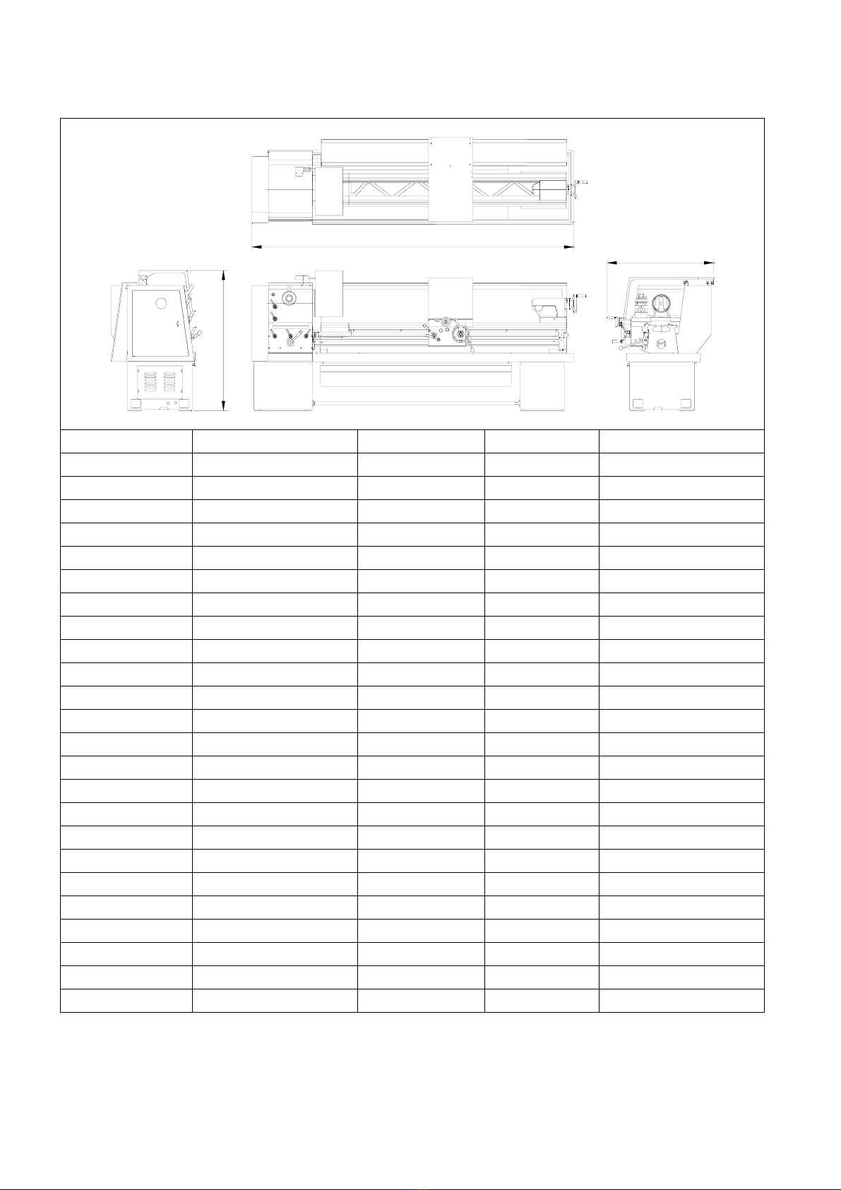
CONVENTIONAL LATHE Overall drawing
AB
C
Model A B C
Prince 1330 Prince 750 1550 724 1175
Prince 1340 Prince 1000 1800 724 1175
Studturn 1430 Studturn 750 1610 888 1223
Studturn 1440 Studturn 1000 1864 888 1223
Champion 1530 Champion 760 1955 1031 1232
Champion 1540 Champion 1000 2205 1031 1232
Champion 1550 Champion 1250 2455 1031 1232
Major 1840 Major 1800-1000 2237 1086 1325
Major 1860 Major 1800-1500 2745 1086 1325
Major 1880 Major 1800-2000 3254 1086 1325
Major 2040 Major 2000-1000 2237 1086 1349
Major 2060 Major 2000-1500 2745 1086 1349
Major 2080 Major 2000-2000 3254 1086 1349
Major 2240 Major 2200-1000 2237 1086 1375
Major 2260 Major 2200-1500 2745 1086 1375
Major 2280 Major 2200-2000 3254 1086 1375
General 2660 General 2600-1500 3900 2000 1700
General 2680 General 2600-2000 4425 2000 1955
General 3060 General 3000-1500 3900 2000 1700
General 3080 General 3000-2000 4425 2000 1955
Trainer 1330 Trainer 1330 1640 1060 1580
Trainer 1340 Trainer 1340 1940 1060 1580
Trainer 1430 Trainer 1430 1640 1060 1900
Trainer 1440 Trainer 1440 1940 1060 1900
.
7
Major 18120 Major 1800-3000 4265 1086 1325
Major 20120 Major 2000-3000 4265 1086 1349
Major 22120 Major 2200-3000 4265 1086 1375
General 26120 General 2600-3000 5425 2000 1955
General 26160 General 2600-4000 6425 2000 1955
General 30120 General 3000-3000 5425 2000 1955
General 30160 General 3000-4000 6425 2000 1955
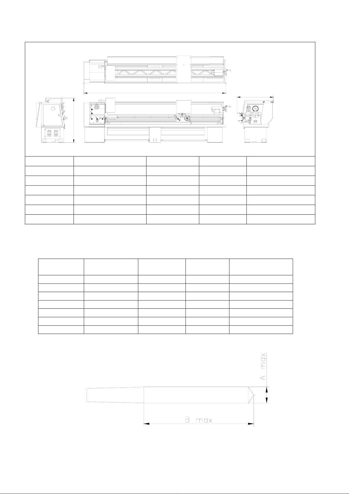
TOOL INFORMATION
MODEL Tool shank(mm) Tailstock drill
A(mm) Tailstock drill
B(mm) Tailstock drill
Max. Weight(kg)
PRINCE 20 18 100 3.5
STUDTURN 20 18 100 3.5
CHAMPION 25 24 120 5
MAJOR 25 24 120 7
GENERAL 25 31 150 10
TRAINER 20 18 100 3.5
KNIGHT 25 24 120 5
AB
C
8
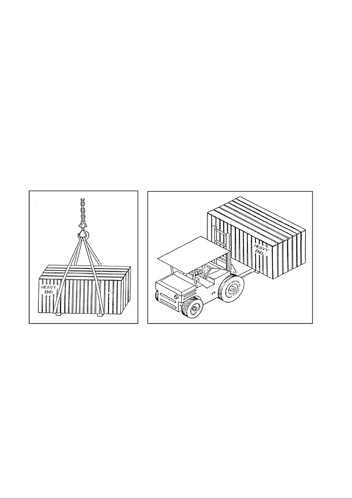
LIFTING MACHINE BEFORE UNPACKING
Normally, each lathe was packed with seaworthy strong wooden case. Before
unpacking the wooden case to lifting or unloading the lathe, must be ensure
the following notes:
1 .the capacity of lift equipment is adequate for the machines.
2.keep the heavy end fully supported and balanced when lifting.
3.the MACHINE WEIGHTS (Approx. Gross weights):
1330 750KGS. (1650LBS); 1340 820KGS. (1800LBS)
4.the only recommended lifting equipments are hoist/crane and forklift as shown below:
UNPACKING AND LIFTING
UNPACKING THE WOODEN CASE
1 .Locate the wooden case on a flat and sufficient area for easy working.
2.Clean the area and space.
3.Wear gloves and suitable safety equipments.
4.Use the claw hammer or nail extractor to pull out nails, especially the nails on sheet bands at four top corners.
5.0pen the top cover first.
6..Pull down the four side covers carefully. WARNING: Be careful of sharp nails.
7.Remove any broken wood pieces that might cause damage to the lathe.
8.Remove all the accessories packed on the wooden base.
9.Loosen and remove all the nuts mounted to the thru bolts, holding the lathe to the wooden shipping skid.
10.Clean all the nails and packing materials around the area.
WARN ING: Headstock end of Lathe is "HEAVY END"
,
Make sure this end is full
y
su
pp
orted.
9
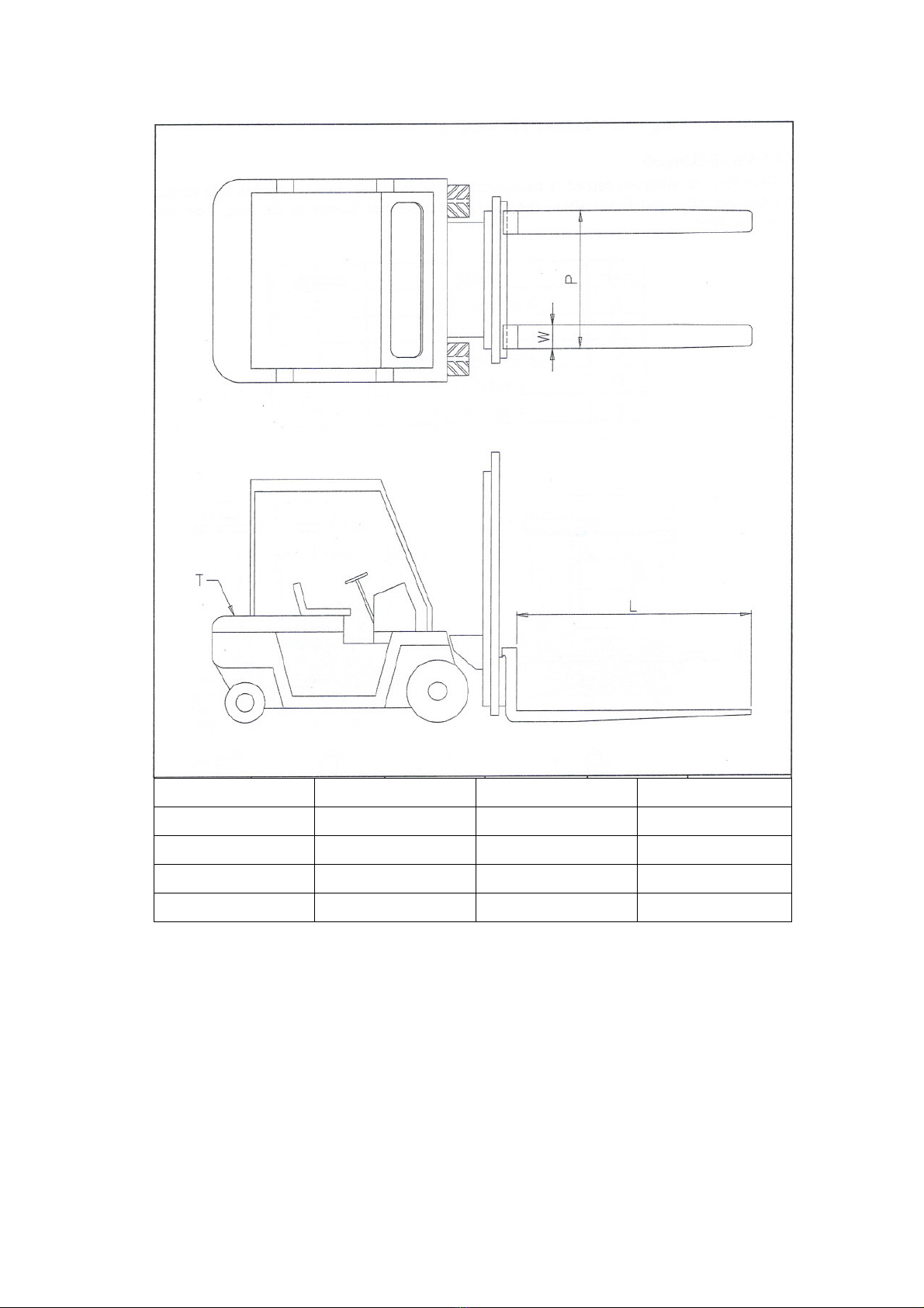
THE FORKLIFT TRUCK CAPACITY
T(ton) L W P
2.5 1350 1200 1100
4.5 1820 1500 1250
8 2450 1800 1850
12 2450 1800 2000
Please pay attention to transport and lift this high precision machine for avoiding any strong
extrusions or collisions. The lifting capacity of forklift truck must be sufficient for the machine.
Table shows the forklift truck capacity.
10
LlFTING
PREPARATION AND SAFETY CHECK
1 .Remove all loose items of equipment and accessories
from lathe.
2.Move the tailstock and carriage assembly to the far end
of the lathe and clamp them in place, (see drawing below)
3.Make sure that the eyebolt and clamp are tightened on
the bed correctly.
4."NEVER" used a damaged sling and "DO-NOT" use more
than one(1) sling.
5."NEVER" wrap the sling around the bed to lift the
machine; the leadscrew, feedshaft and control rod will
become bent or damaged nagating the warranty on the
machine.
6.0nly a hoist or crane is recommended for lifting the lathe.
Fork lift blades should never be put under the lathe for
lifting.
7.Make sure that the lifting hook is a "Swivel" type with
safety latch.
8.Just before making the final lift, make sure one (1) person
makes a final examination all around the lathe double
checking everything.
9.Lift cleanly of all ground obstacles and do not drag the
machine across the floor.
10.Remember that vibration during transport can
cause friction between the sling and the machine.
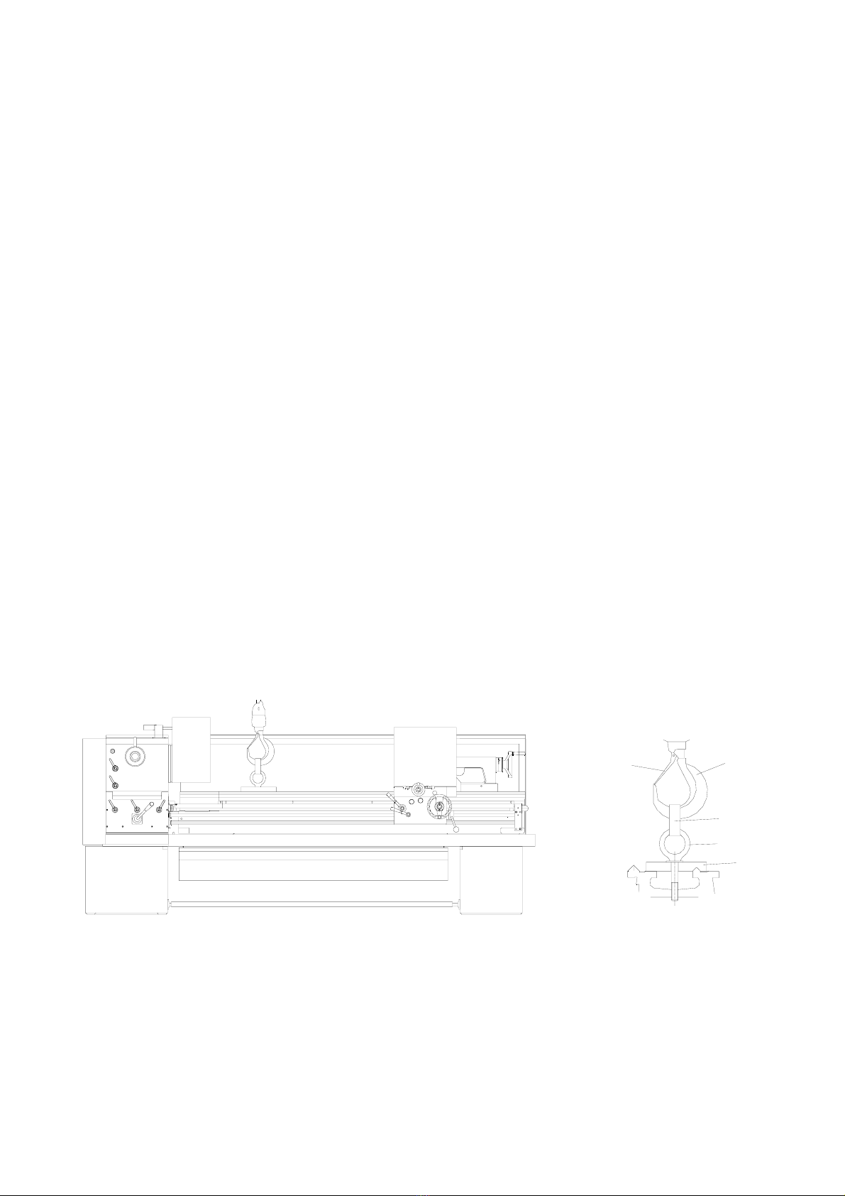
LIFTING THE MACHINE
1 .Lift the lathe by hoist/crane as shown in the drawing
below.
2.Make sure that a safety-latch type swivel hook is used and
that the eyebolt clamp was tightened properly to the bed.
3.If the larger swivel hook can not fit into the eyebolt, an
intermediate sling can be used as shown in the drawing
below.
4.Carefully and slowly lift the lathe clear of the wooden base
or ground and, if necessary, reposition the carriage or
tailstock to achieve a better balance before lifting any
higher or further.
5.If you reposition the carriage or tailstock, make sure you
re-tighten and lock them in place.
6. After a full load is on the main hook, check to make sure
that the lifting hook swivels freely and not putting any
twisting stress on the eyebolt which might loosen it up.
7.Lift and move the lathe very slowly to avoid tilting or rocking
the machine which could become dangerous.
8.Keep the lathe low to the ground with only the necessary
ground clearance to move the machine freely over the
surface.
9.For transhipping the lathe without repacking onto a skidbase,
it is recommended to lift the machine straight up to the
desired height and drive a flat bed truck underneath it for
loading. This is a safer method of moving the machine than
moving with a crane.
BEFORE LIFTING: Help balance the load by sliding the tailstock to
the extreme opposite end of the bed ways and lock it in place. If necessary,
move carriage assembly to tailstock end for balance position and lock it.
Safety
Latch
Swivel
Hook
Sling
Eyebolt
Clamp
WARNING
UNAUTHORIZED LIFTING OF THE MACHINE BY NON-CERTIFIED RIGGERS AND ANY NEGLECT caused BY
SUCH ACTION MAY CAUSE SERIOUS DAMAGE TO PERSONS AND PROPERTY. MANUFACTURER AND
DISTRIBUTORS SHALL NOT BE LIABLE FOR ANY DAMAGES RESULTING FROM THE FAILURE TO USE
LICENSED AND CERTIFIED RIGGERS TO LIFT AND/OR MOVE THIS EQUIPMENT.

11
OPERATING SAFETY PRECAUTIONS
1.ARE YOU PROPERLY TRAINED PERSONNEL TO USE THIS LATHE?
2.READ THIS INSTRUCTION MANUAL CAREFULLY BEFORE OPERATION.
3.ENSURE YOU KNOW HOW TO STOP THE LATHE BEFORE STARTING IT
4.ENSURE YOU ARE IN GOOD HEALTH AND SPIRIT TO OPERATE THE LATHE.
5.KEEP ALL GUARDS, COVERS AND DOORS IN PLACE AND CLOSED.
6.KEEP THE LATHE AND WORK AREA NEAT, CLEAN AND ORDERLY.
7.WEAR AND UTILISE SUITABLE PROTECTIVE CLOTHING AND EQUIPMENT.
8.DO NOT WEAR RINGS, WATCHES, TIES OR LOOSE SLEEVED CLOTHING.
9.NEVER LAY ANYTHING ON THE WORKING SURFACE OF THE LATHE.
10.STOP LATHE IMMEDIATELY ANYTHING UNEXPECTED HAPPENS.
11.DO NOT TOUCH OR REACH OVER ROTATING OR MOVING PARTS.
12.DO NOT PERFORM ANY SET-UP WORK WHILE LATHE IS RUNNING.
13.DO NOT OPERATE THE LATHE IN EXCESS OF ITS RATED CAPACITY.
14.DO NOT INTERCHANGE CHUCKS OR OTHER SPINDLE MOUNTING ITEMS WITHOUT CHECKING FOR
CORRECT LOCKING.
15.DO NOT USE OTHER WORKHOLDING DEVICE WITHOUT CHECKING WITH ITS MANUFACTURER.
16.DISCONNECT LATHE FROM POWER SOURCE BEFORE PERFORMING ANY MAINTANENCE OR
CHANGING TOOLING.
17.ISOLATE LATHE WHEN LEAVING IT UNATTENDED.
18.THE MACHINE IS NOT ALLOWED TO WORK WITH FLAMMABLE METAL WORKING FLUIDS OR
MATERIALS AS ALUMINUM OR MAGNESIUM, WHICH CAN CAUSE FIRE AND EXPLOSION OR
NOXIOUS DUST.
19.DON’T WEAR GLOVES DURING OPERATION, ONLY WHEN LOADING AND UNLOADING WORKPIECE
COULD WEAR GLOVES.
20.BALANCE REQUIREMENTS ON WORKPIECE CLAMPING DEVICE SHALL BE FOLLOWED: WORKPIECE
CLAMPING DEVICES SHALL ONLY BE MODIFIED IN ACCORDANCE WITH THE CLAMPING DEVICE
MANUFACTURER’S RECOMMENDATIONS.
21.SHALL BE PROVIDED THAT MACHINING UNBALANCED WORKPIECE MAY CREATE AN EJECTION
HAZARD AND THAT MEANS OF MINIMING THE RISK IS COUNTER BALANCING OR MACHINING AT
REDUCED SPEED.
22.CHUCK GUARD AND CHIP GUARD ARE ABLE TO REDUCE MOST OF RISKS, BUT UNAVAILABLE TO
PREVENT 100% RISK.
23.Machine can’t be started if safety device is opened.
THE EXPECTED LIFE OF THE MACHINE IS COUNTED AS:
8 HRS X 5.5 DAYS X 45 WEEKS X 10 YEARS = 19800 HRS
WHICH TO BE UNDER NORMAL OPERATION AND WELL MAINTENANCE.
IT IS NOT NECESSARY TO REPLACE MANY COMPONENTS EXCEPT THOSE ARE CONSUMABLE.

12
NOISE LEVEL
.
Equivalent A-weighted Sound pressure level according to EN ISO 3746: 75.6 dB(A) for,MJ 2260
Reflecting
plane
Reference
box
Path 1
Path 2 Path 3
6
7
8
5
1
4
32
9
NOTE:
Uncertainty, K in decibels: 4.0 dB (A) according to EN ISO 4871
The figure quoted is emission levels and are not necessarily safe working levels. Whilst there is a correlation
between the emission and exposure levels, this cannot be used reliably to determine whether or not further
precautions are required. Factors that influence the actual level of exposure of the workforce include
characteristics of the workroom, the other sources of noise, etc. i.e. the number of machines and other adjacent
processes. Also the permissible exposure level can vary from country to country. This information, however, will
enable the user of the machine to make a better evaluation of the hazard and risk.

13
ACCIDENTS AT LATHES BY USING EMERY CLOTH
DANGER: Any strips of Emery Cloth there is a Danger of Trapping.
HAZARDS
A high proportion of all accidents at metalworking lathes involve the use of Emery Cloth and result in injuries such as broken
occasionally amputated fingers. Emery Cloth is used to deburr, polish or size a wide range of cylindrical, tapered and
threaded metal components while they are rotating in lathes. Most accidents happen when each end of a strip of Emery Cloth
is held in separate hands and passed around the back of the component being linished. If the Cloth is wrapped around the
fingers and/or becomes snagged on the component while it is tightly gripped, then a serious injury is the likely result.
PRECAUTIONS
Emery cloth should NEVER be used at CNC lathes. Employers should assess the need to use emery cloth on components in
a lathe.
Such operations may not be necessary if:
(a) the finish being sought is only cosmetic. For such finishes the component may be held in one hand and polished by
Emery Cloth held in the other. Alternatively a linishing belt or machine be used.
(b) a sizing operation can be successfully performed either by turning or by further operations machine. In a dedicated
polishing, linishing or grinding machine.
DANGER: Emery Cloth should never be held loose in the hand.
14
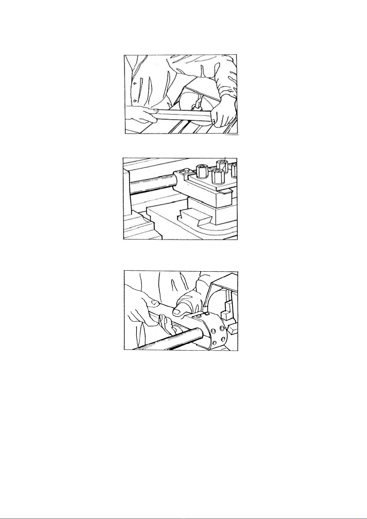
If the required tolerance is only achievable by the use of Emery Cloth against rotating components, then the Emery Cloth
should be applied using either:
(a) A backing board of good quality wood as figure (a)
Fig a
(b) A toolpost onto which the Emery Cloth may be placed as figure (b);
Fig b
(c) A 'nutcracker' consisting of two backing boards which are lined with Emery Cloth and joined at end and shaped so that they
may encompass the surface to be linished as figure (c) ;
Fig c
(d) Or hand-held abrasive-impregnated wire brushes.
WARNING
Gloves should never be worn when polishing is being carried out.
Where none of the above methods is reasonably practicable and it is necessary to use Emery Cloth for polishing the outside
diameters of components, the Emery Cloth should be used in long strips with one end passed beneath the component.
Force should be applied by pulling both ends of the cloth upwards, never allowing the cloth to go slack or to wrap around either
the operator's finger or the components.
For polishing the ends of components, only very short lengths or pads of cloth should be used which are incapable of causing
entanglements.

15
OPERATION
LEGEND
1. HEADSTOCK
2. MAIN SPINDLE & CHUCK
3. CARRIAGE
4. CROSS SLIDE
5. TOOLPOST
6. COMPOUND SLIDE
7. THREADING DIAL
8. TAILSTOCK CENTER
9. TAILSTOCK LOCK LEVER
10. TAILSTOCK
11. TAILSTOCK HANDWHEEL
12. BED
13. CABINET
14. LEADSCREW
15. HALF NUT LEVER
16. FEED ROD
17. CROSS/LONGITUDINAL FEED KNOB
18. FEED ENGAGEMENT KNOB
19. CARRIAGE HANDWHEEL
20. CROSS SLIDE HANDWHEEL
21. CHIP PAN
22. QUICK CHANGE GEAR BOX
23. GEAR SHIFT KNOB
24. FEED OR THREAD CHANGE KNOB
25. QUADRANT COVER
26. FEEDING DIRECTION SELECT KNOB
27. ELECTRICAL CONTROL PANEL
28. FEED & THREAD SELECTOR KNOB
29. SPINDLE SPEED SELECTOR
30. FOR./OFF/REV. CONTROL SHAFT
31. SPINDLE ROTATION CONTROL LEVER
16
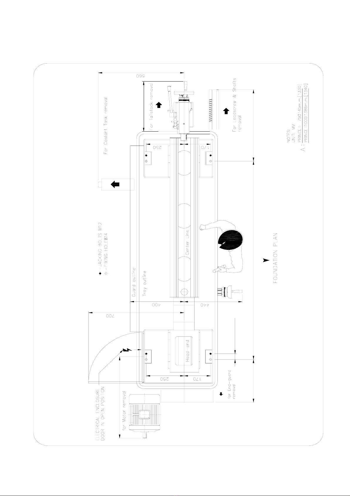
FOUNDATION PLAN
300
?40X4HOLES
A
350
500
570
17
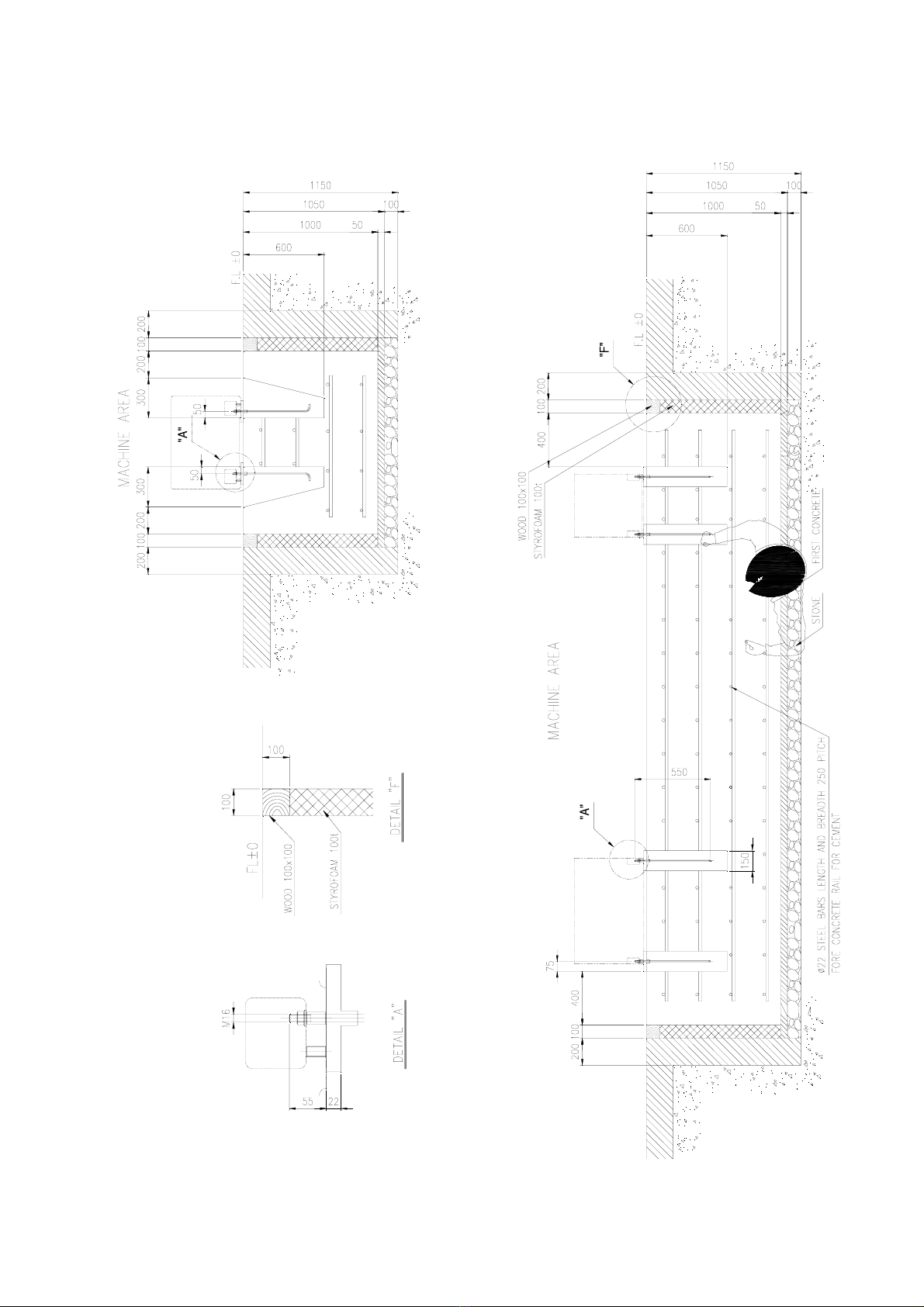
ANCHOR BOLT DIAGRAM
18
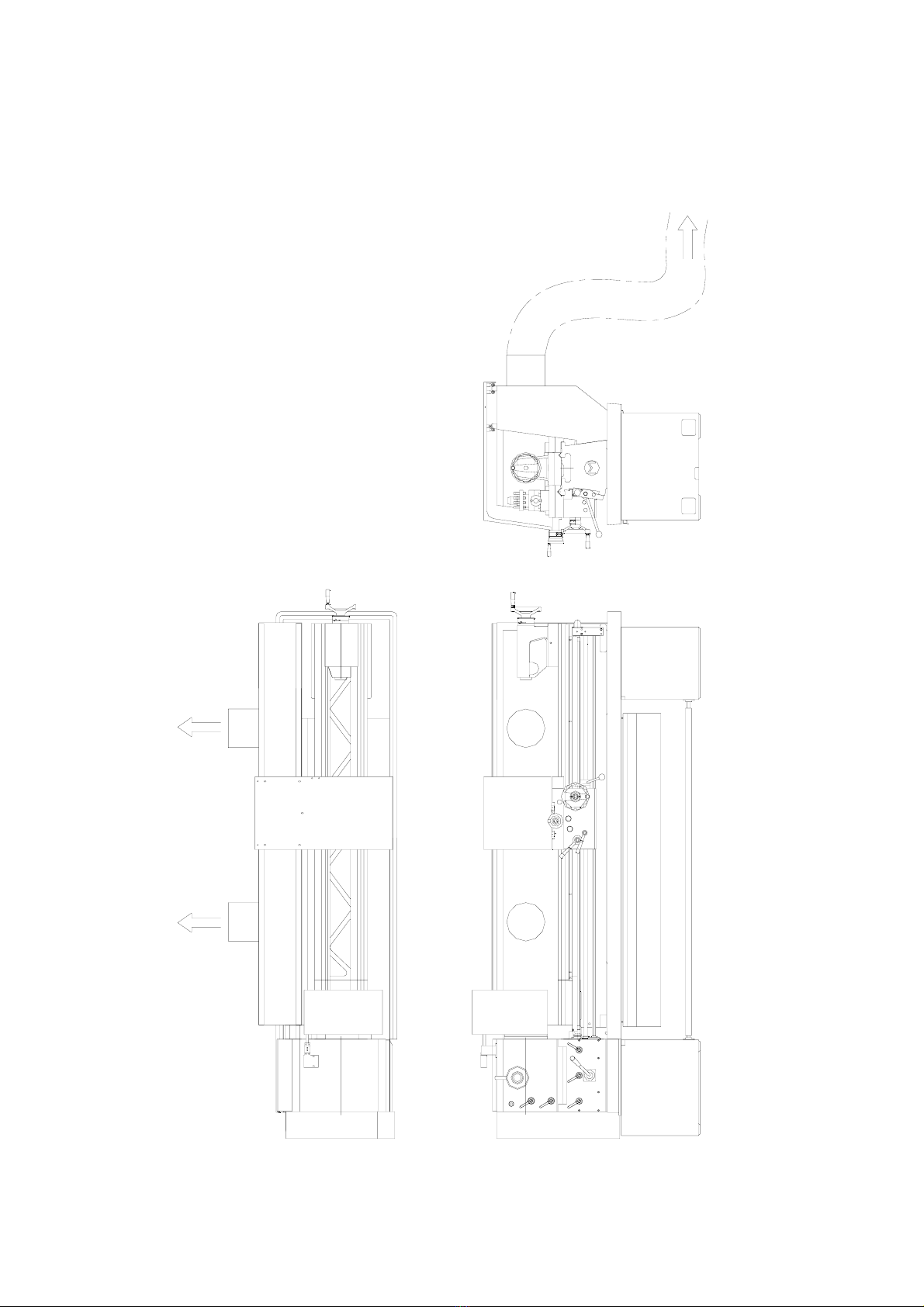
CONNECTION OF EXTRACTION SYSTEM
18"
To Extraction
System
18"

19
ILLUSTRATION OF HAZARD REGION
Arrow shows the directions of movement in the danger area.
SPINDLE
SADDLE
CROSS
SLIDE
Item Name
1Chip Guard (moveable guard)
2Chuck Guard
3Heanend Guard
4Rear Guard
5 The area between the leadscrew
and second rod
1
2
34
5
Table of contents
Popular Lathe manuals by other brands

Record Power
Record Power Coronet Series Original instruction manual

King Industrial
King Industrial KC-1022ML instruction manual

Clarke
Clarke WOODWORKER CWL325V Operation & maintenance instructions

Jet
Jet BDB-1340A Assembly instructions

Sherline Products
Sherline Products 4410 operating instructions

Axminster Craft
Axminster Craft AC370WL Original instructions

Grizzly
Grizzly G0657 owner's manual

MachineryHouse
MachineryHouse Hafco Metalmaster SRG-12 Operation manual

Scheppach
Scheppach DM1100T Translation of the original instruction manual

laguna
laguna Revo 2036 instruction manual

Jet
Jet BDB-919 Operating instructions and parts manual

Auto Mate
Auto Mate Raptor TC-1417 manual


