Grizzly G0600 User manual

WARNING: NO PORTION OF THIS MANUAL MAY BE REPRODUCED IN ANY SHAPE
OR FORM WITHOUT THE WRITTEN APPROVAL OF GRIZZLY INDUSTRIAL, INC.
Lubrication MAINTENANCE
Page 52
If you have any questions about this manual insert or machine lubrication and break-in, please contact
MODEL G0600
20" x 60" BIG BORE
LATHE
MANUAL INSERT
GEARBOXES MUST
BE FILLED WITH OIL!
NO OIL SHIPPED WITH
MACHINE!
Requires ISO 68
or Non-Detergent
SAE 20W Motor Oil.

MODEL G0600
20" x 60" BIG BORE LATHE
OWNER'S MANUAL
COPYRIGHT © APRIL, 2007 BY GRIZZLY INDUSTRIAL, INC. REVISED SEPTEMBER 2007.
WARNING: NO PORTION OF THIS MANUAL MAY BE REPRODUCED IN ANY SHAPE
OR FORM WITHOUT THE WRITTEN APPROVAL OF GRIZZLY INDUSTRIAL, INC.
#CR9070 PRINTED IN CHINA


Table of Contents
INTRODUCTION ............................................................................................................................... 3
Foreword .................................................................................................................................... 3
Contact Info ................................................................................................................................ 3
G0600 Data Sheet ..................................................................................................................... 4
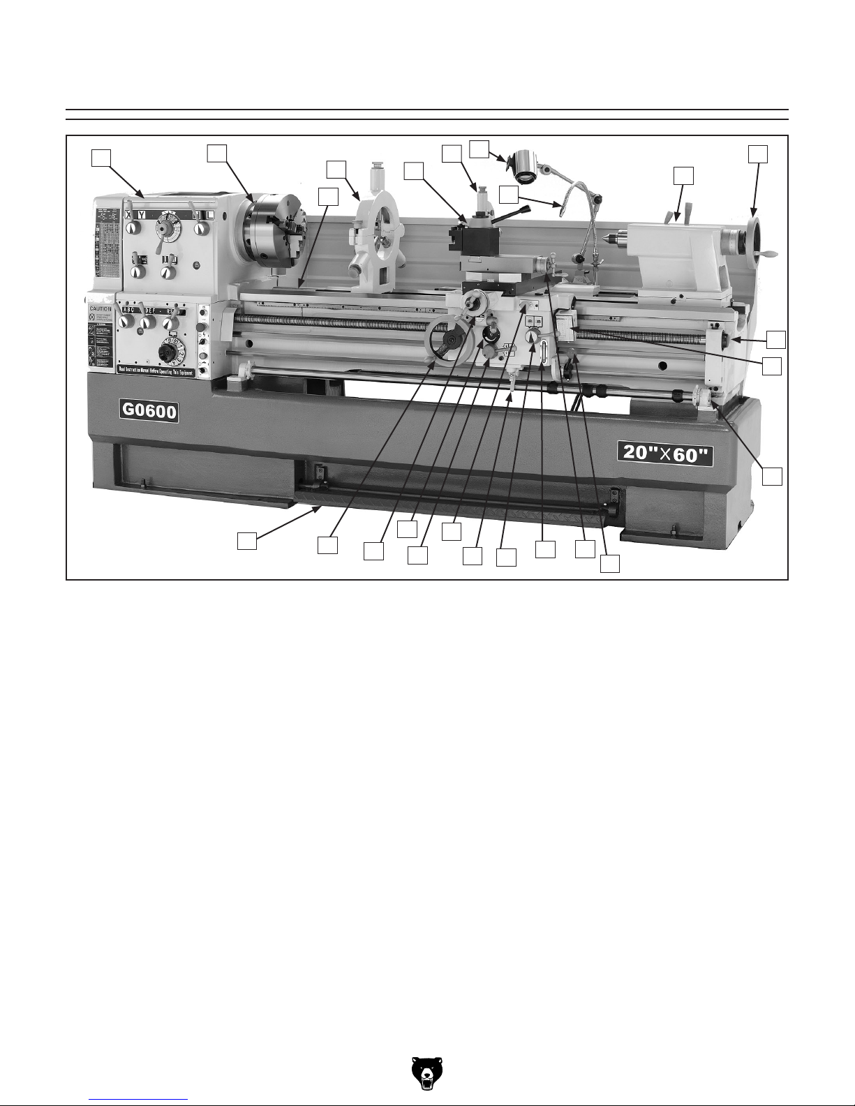
Identification ............................................................................................................................... 7
Headstock Controls .................................................................................................................... 8
SECTION 1: SAFETY ....................................................................................................................... 9
Additional Safety for Metal Lathes ........................................................................................... 11
Glossary of Terms .................................................................................................................... 12
SECTION 2: CIRCUIT REQUIREMENTS ...................................................................................... 13
220V 3-Phase .......................................................................................................................... 13
Operation .................................................................................................................................. 13
Phase Converter ...................................................................................................................... 13
SECTION 3: SETUP ....................................................................................................................... 14
Setup Safety ............................................................................................................................. 14
Items Needed for Setup ........................................................................................................... 14
Unpacking ................................................................................................................................ 14
Inventory ................................................................................................................................... 15
Hardware Recognition Chart .................................................................................................... 16
Site Considerations .................................................................................................................. 17
Lifting & Moving the Lathe ....................................................................................................... 18
Cleanup .................................................................................................................................... 19
Test Run ................................................................................................................................... 20
Changing Motor Rotation ......................................................................................................... 22
Apron and Spindle Break-in .................................................................................................... 23
Spindle Balancing ................................................................................................................... 23
SECTION 4: OPERATIONS ........................................................................................................... 24
Operation Safety ...................................................................................................................... 24
General ..................................................................................................................................... 24
Chuck and Faceplate ............................................................................................................... 25
Mounting ................................................................................................................................. 25
Camlock Stud Adjustment ........................................................................................................ 27
Reversing Jaws ........................................................................................................................ 28
Gap Removal ........................................................................................................................... 29
Tailstock ................................................................................................................................... 29
Aligning Tailstock ..................................................................................................................... 30
Drilling with Tailstock ................................................................................................................ 31
Cutting Tapers with Tailstock ................................................................................................... 31
Centers ..................................................................................................................................... 32
Steady Rest .............................................................................................................................. 33
Follow Rest .............................................................................................................................. 34
Setting Compound Slide .......................................................................................................... 34
Quick Change .......................................................................................................................... 35
Tool Post .................................................................................................................................. 35
Foot Brake ................................................................................................................................ 35
Setting Spindle RPM ................................................................................................................ 36
Manual Feed ............................................................................................................................ 38
Power Feed .............................................................................................................................. 38
Four-Position Apron Stop ......................................................................................................... 39
Starting Lathe ........................................................................................................................... 40
Using the Thread Chart ............................................................................................................ 41
Dimetrial and Modular Pitch Threading .................................................................................... 42
Inch and Metric Pitch Threading .............................................................................................. 44
Thread Dial ............................................................................................................................... 46

SECTION 5: ACCESSORIES ......................................................................................................... 47
SECTION 6: MAINTENANCE ........................................................................................................ 52
Schedule .................................................................................................................................. 52
Cleaning ................................................................................................................................... 52
Lubrication ................................................................................................................................ 52
Coolant System ........................................................................................................................ 56
SECTION 7: SERVICE ................................................................................................................... 57
Troubleshooting ........................................................................................................................ 57
Cross Slide Leadscrew Adjustment ......................................................................................... 60
Leadscrew Endplay Adjustment ............................................................................................... 60
Gib Adjustment ......................................................................................................................... 61
Halfnut Adjustment ................................................................................................................... 62
Feed Clutch Adjustment ........................................................................................................... 62
V-Belts ...................................................................................................................................... 63
Brake and Switch ..................................................................................................................... 63
Control Panel Electrical ............................................................................................................ 64
Switch and Motor Electrical ...................................................................................................... 65
Main Electrical Box ................................................................................................................... 66
Model G0600 Electrical Diagram ............................................................................................. 67
Headstock Gear System .......................................................................................................... 68
Headstock Face and Shift System ........................................................................................... 69
Headstock Shift System ........................................................................................................... 70
Headstock Oil Pump System ................................................................................................... 71
Quick Change Gearbox Gear System ..................................................................................... 75
Quick Change Gearbox Face .................................................................................................. 76
Quick Change Gearbox Shift System ...................................................................................... 77
Quick Change Gearbox Shift System ...................................................................................... 78
Carriage .................................................................................................................................... 81
Cross Slide and Carriage ......................................................................................................... 82
Compound Rest and Tool Post ................................................................................................ 83
Carriage Oil Pump System ...................................................................................................... 84
Apron Face, Thread Dial, Auto Stop System ........................................................................... 87
Apron Gearing, Halfnut, Feed System ..................................................................................... 88
Apron Feed Rod, Clutch and Lever System ............................................................................ 89
Tailstock ................................................................................................................................... 92
Bed Assembly ......................................................................................................................... 94
Brake Pedal and Headstock Panels ....................................................................................... 95
Brake System and Change Gears ........................................................................................... 96
Motor and Headstock Mounting ............................................................................................... 97
End Covers and Splash Guard ................................................................................................ 98
Change Gear System ............................................................................................................... 99
Steady and Follow Rests ....................................................................................................... 102
Accessories, Coolant, and Lighting System ........................................................................... 104
Main Electrical Box ................................................................................................................. 105
WARRANTY AND RETURNS ...................................................................................................... 106

G0600 20" x 60" Big Bore Lathe -3-
If you have any comments regarding this manual,
please write to us at the address below:
Grizzly Industrial, Inc.
C/O Technical Documentation Manager
P.O. Box 2069
Bellingham, WA 98227-2069
Email: [email protected]
We stand behind our machines. If you have any
service questions or parts requests, please call or
write us at the location listed below.
Grizzly Industrial, Inc.
1203 Lycoming Mall Circle
Muncy, PA 17756
Phone: (570) 546-9663
Fax: (800) 438-5901
E-Mail: [email protected]
Web Site: http://www.grizzly.com
Foreword
INTRODUCTION
Contact Info
We are proud to offer the Model G0600 20" x 60"
Big Bore Lathe. This machine is part of a growing
Grizzly family of fine metalworking machinery.
When used according to the guidelines set forth in
this manual, you can expect years of trouble-free,
enjoyable operation and proof of Grizzly’s com-
mitment to customer satisfaction.
We are pleased to provide this manual with
the Model G0600. It was written to guide you
through assembly, review safety considerations,
and cover general operating procedures. It repre-
sents our effort to produce the best documenta-
tion possible.
The specifications, drawings, and photographs
illustrated in this manual represent the Model
G0600 as supplied when the manual was pre-
pared. However, owing to Grizzly’s policy of con-
tinuous improvement, changes may be made at
any time with no obligation on the part of Grizzly.
For your convenience, we always keep current
Grizzly manuals available on our website at www.
grizzly.com. Any updates to your machine will be
reflected in these manuals as soon as they are
complete. Visit our site often to check for the lat-
est updates to this manual!

-4- G0600 20" x 60" Big Bore Lathe
Customer Service #: (570) 546-9663 • To Order Call: (800) 523-4777 • Fax #: (800) 438-5901

G0600 20" x 60" Big Bore Lathe -5-

-6- G0600 20" x 60" Big Bore Lathe

G0600 20" x 60" Big Bore Lathe -7-
Figure 1. The Model G0600 20" x 60" Big Bore Lathe.
Identification
M. 4-Position Apron Stop Dial
N. Spindle Rotation ON/OFF Lever
O. Compound Rest Handwheel
P. Apron Oil Level Sight Glass
Q. Halfnut Lever
R. Apron Release Arm
S. Manual Oil Pump
T. Feed Clutch Lever
U. Feed Clutch Tension Adjustment
V. Cross Slide Handwheel
W. Apron Handwheel
X. Brake Pedal
A. Headstock
B. D1-8 Camlock MT#7 Spindle
C. Gap Piece
D. Ball Bearing Style Steady Rest
E. Quick Change Tool Holder
F. Follow Rest
G. Work Lamp
H. Universal Coolant Nozzle
I. Tailstock
J. Tailstock Handwheel
K. Leadscrew Rod Endcap Housing
L. Thread Dial
AB
C
D
G
E
F
H
I
J
L
K
M
Q
WT
U
VR
S
P
XON

-8- G0600 20" x 60" Big Bore Lathe
Headstock Controls
A. Cutting Chart: Used for shifting the lathe
headstock and gearbox into the proper gear
combinations for threading and feeding oper-
ations.
B. Range Splitting Lever: Used to select the
final spindle speed from the set of high or low
range speeds selected by the range lever.
C. Spindle Speed Dial: Positions the head-
stock gears in one of three speed modes. In
each mode, there are four spindle speeds.
The four speed choices are two speeds in
low range, and two speeds in high range. The
range lever selects high or low range, and the
range splitting lever selects one of the two
remaining speeds within that range.
D. Range Lever: Used to select a set of high
or low range spindle speeds from one of the
three spindle speed modes shown on the
spindle speed dial.
E. Gearbox Hi/Lo Lever: This lever puts the
gearbox in high or low range and has no
effect on spindle RPM. I is Hi range, II is low
range.
F. Jog Button: Turns the spindle motor ON
while being pressed and held.
G. Feed/Lead Dial: Used for setting up feed or
threading gearing ratios in conjunction with
quick change gearbox levers.
H. Emergency Stop Button: Stops all machine
functions. Twist clockwise to reset.
I. Lathe Power Switch: Turns power ON/OFF
to the lathe so lathe operations can begin.
J. Power Light: Indicates the lathe is ener-
gized when illuminated.
K. Coolant Pump Switch: Turns coolant pump
ON/OFF.
L. Quick Change Gearbox Levers: Moves the
gearbox gears into particular ratios, which
then turn the leadscrew and feedrod for
threading and power feed operations.
M. Leadscrew/Feedrod Direction Lever:
Changes the rotation direction of the
leadscrew or feedrod so apron or cross feed
will move the opposite direction.
Figure 2. Headstock and gearbox controls.
A
L
K
I
J
H
F
E
D
CB
M
G

G0600 20" x 60" Big Bore Lathe -9-
SECTION 1: SAFETY

-10- G0600 20" x 60" Big Bore Lathe

G0600 20" x 60" Big Bore Lathe -11-
Additional Safety for Metal Lathes
1. READ AND UNDERSTAND THIS
MANUAL BEFORE OPERATING THIS
MACHINE. YOUR SAFETY AND THE
PROPER USE OF THIS MACHINE IS
YOUR RESPONSIBILITY.
2. CLEARING CHIPS. Do not clear chips by
hand or while the lathe is turning.
3. CHUCK KEY SAFETY. Always remove
chuck key. Never walk away from the lathe
with the key in the chuck.
4. TOOL SELECTION. Always select the right
cutter for the job, and make sure they are
sharp. The right tool decreases strain on
the lathe components and provides a better
finish.
5. SECURING THE WORKPIECE. Make sure
workpiece is properly held in chuck before
starting lathe. A workpiece thrown from the
chuck may cause severe injury to yourself
or others.
6. CHANGING GEARS. Turn lathe OFF before
changing speeds. The spindle must be
brought to a complete stop before changing
gears.
7. SUPPORT LONG STOCK. Stock extending
beyond the headstock MUST be supported.
Unsupported stock will begin to whip and
cause serious injury to operator/ bystanders
and cause damage to the lathe. Always turn
supported long stock at slow RPM's.
8. PINCH HAZARDS. Protect your hands and
the precision ground ways. Always use a
chuck cradle or piece of plywood over the
ways of the lathe when servicing chucks.
9. LATHE MAINTENANCE. Never operate
the lathe with damaged or worn parts.
Maintain your lathe in proper working condi-
tion. Perform routine inspections and main-
tenance promptly when needed. Put away
adjustment tools after use.
10. SAFETY CLEARANCES. Make sure
workpiece has adequate clearance before
starting machine. Check tool and tool post
clearance, chuck clearance, and saddle
clearance before starting the lathe.
11. RATES. Always use the appropriate feed
and speed rates.
12. STOPPING LATHE. Never attempt to slow
or stop the lathe chuck by using your
hand.
13. ATTENDANCE. Never walk away from the
lathe while it is running. An unsupervised
lathe that is running invites accidents.
14. LONG HAIR. Tie up long hair. Long hair
poses a risk of entanglement with moving
parts.
15. AUTOMATIC FEEDS. Release any auto-
matic feeds after completing a job.
16. TURNING SPEEDS. Select the turning
speed appropriate for the type of work,
material, and tool bit. Allow the lathe to gain
full speed before beginning a cut.
17. MOTOR DIRECTION. Never reverse motor
direction while the lathe is in motion.
18. GUARDS. Make sure all guards are in
place and working properly.
19. TOOL POST CLEARANCE. Adjust tool
post to provide proper support for the turn-
ing tool you will be using. Test tool post
clearance by rotating workpiece by hand
before turning lathe ON.
20. CRASHES. Make sure no part of the tool,
tool holder, compound slide, cross slide,
or carriage will contact the chuck during
operation.

-12- G0600 20" x 60" Big Bore Lathe
The following is a list of common definitions, terms and phrases used throughout this manual as they relate
to this lathe and metalworking in general. Become familiar with these terms for assembling, adjusting or
operating this machine. Your safety is VERY important to us at Grizzly!
Arbor: A machine shaft that supports a cutting
tool.
Backlash: Wear in a screw or gear mechanism
that may result in slippage, vibration and loss
of tolerance.
Collet: A conical shaped split-sleeve bushing
that holds round or rectangular tool and/or
workpieces by their outside diameter.
Cross slide: Movement of cutting tool across the
end of the workpiece.
Cross Slide: A fixture attached to the lathe car-
riage that holds the compound rest and can
be moved in and out.
Cutting Speed: The distance a point on a cutter
moves in one minute, expressed in meters or
feet per minute.
Dial Indicator: An instrument used in setup and
inspection work that shows on the amount of
error in size or alignment of a part.
Facing: In lathe work, cutting across the end of a
workpiece, usually to machine a flat surface.
Feed: The movement of a cutting tool into a
workpiece.
Fixture: A device that securely holds the
workpiece in place during cutting operation
as opposed to a Jig which is used to hold
and guide a workpiece through an opera-
tion.
Gib: A tapered wedge located along a sliding
member to take up wear or to ensure a
proper fit.
Headstock: The major lathe component that
houses the spindle and motor drive system
to turn the workpiece.
Lathe Center: A lathe accessory with a 60°
point which is inserted into the headstock or
tailstock of the lathe and is used to support
the workpiece.
Leadscrew: The long screw that is driven by the
end gears and supplies power to the car-
riage.
Spindle: The revolving shaft that holds and
drives the workpiece or cutting tool.
Tailstock: A moveable fixture opposite of the
headstock on a lathe that has a spindle used
to support one end of a workpiece and for
holding tools.
Toolpost: The part of the compound rest that
holds the tool holder.
Turret: A machine fixture that holds multiple tools
and can be revolved and indexed to posi-
tion.
Ways: The precision machined and flat tracks on
a lathe on which the carriage and tailstock
slide.
Glossary of Terms

G0600 20" x 60" Big Bore Lathe -13-
SECTION 2: CIRCUIT REQUIREMENTS
Serious personal injury could occur if you
connect the machine to the power source
before you have completed the set up pro-
cess. DO NOT connect the machine to the
power source until instructed to do so.
Full Load Amperage Draw
G0600 10 HP 220V 3-Phase .................28 Amps
Circuit Requirements
We recommend connecting your machine to a
dedicated and grounded circuit that is rated for
the amperage given below. Never replace a circuit
breaker on an existing circuit with one of higher
amperage without consulting a qualified electri-
cian to ensure compliance with wiring codes. If
you are unsure about the wiring codes in your
area or you plan to connect your machine to a
shared circuit, consult a qualified electrician.
Minimum Circuit .......................................40 Amp
220V Connection Type
For 220V 3-phase connection of this lathe, we
recommend hardwiring your machine to a power
supply box with a safety shutoff. A qualified elec-
trician should determine the best cord to use in
your environment.
G0600 220V 3-Phase ............................Hardwire
Grounding
In the event of an electrical short, grounding
reduces the risk of electric shock. The grounding
wire in the power cord must be properly connected
to the grounding prong on the plug; likewise, the
outlet must be properly installed and grounded.
All electrical connections must be made in accor-
dance with local codes and ordinances.
Electrocution or fire could
result if this machine is
not grounded correctly
or if your electrical con-
figuration does not com-
ply with local and state
codes. Ensure compliance
by checking with a quali-
fied electrician!
If your lathe is connected to a phase converter
for 3-phase power, the power from the manufac-
tured power leg (sometimes called the wild wire or
manufactured leg) can fluctuate.
Make sure that when you connect the lathe to the
phase converter that you connect the "Wild Wire"
or the "Manufactured Leg" from the phase con-
verter to the lathe input lead L3. Otherwise, your
lathe may not start properly, and magnetic switch
chatter and transformer damage will occur.
Phase Converter
220V 3-Phase
Operation
Extension Cords
We do not recommend the use of extension cords.
Instead, arrange the placement of your equipment
and the installed wiring to eliminate the need for
extension cords.

-14- G0600 20" x 60" Big Bore Lathe
The Model G0600 was carefully packed when it
left our warehouse. If you discover the machine
is damaged after you have signed for delivery,
please immediately call Customer Service at
(570) 546-9663 for advice.
Save the containers and all packing materials for
possible inspection by the carrier or its agent.
Otherwise, filing a freight claim can be difficult.
When you are completely satisfied with the con-
dition of your shipment, you should inventory the
contents.
Wear safety glasses dur-
ing the entire setup pro-
cess!
This machine presents
serious injury hazards
to untrained users. Read
through this entire manu-
al to become familiar with
the controls and opera-
tions before starting the
machine!
Unpacking
Setup Safety
SECTION 3: SETUP
The following items are needed to complete the
setup process, but are not included with your
machine:
Description Qty
• Fork Lift or Crane (5000 lb capacity) ......... 1
• Lifting Straps (5000 lb capacity each) ........ 2
• Safety Glasses (for each person) .............. 1
• Helper for Moving ....................................... 1
• Solvent for Cleaning ................................... 1
• Shop Rags for Cleaning ............................. 1
Items Needed for
Setup
The Model G0600 is
an extremely heavy
machine. Serious per-
sonal injury may occur if
safe moving methods are
not followed. To be safe,
you will need assistance
and power equipment
when moving the ship-
ping crate and remov-
ing the machine from the
crate.

G0600 20" x 60" Big Bore Lathe -15-
Inventory
Major Inventory 1: (Figure 3) Qty
A. Steady Rest Assembly ............................... 1
B. 18" Faceplate ............................................. 1
C. 12" Three Jaw Chuck (On Lathe) .............. 1
D. 14" Four Jaw Chuck ................................... 1
E. Four-Jaw Chuck Lifting Eye ....................... 1
F. Four Jaw Chuck Key .................................. 1
G. D1-8 Camlock Stud Set .............................. 6
H. Quick Change Tool Holders ....................... 2
I. Cast Iron Foot Pads ................................... 6
J. Follow Rest Assembly ................................ 1
NOTICE
Some hardware/fasteners on the inventory
list may arrive pre-installed on the machine.
Check these locations before assuming that
any items from the inventory list are miss-
ing.
Tool Box Inventory: (Figure 4) Qty
K. Tool Box ..................................................... 1
L. Oil Bottle ..................................................... 1
M. Carriage Lock and Tool Holder Wrench ..... 1
N. Three-Jaw Chuck Wrench .......................... 1
O. Gap Pin Puller ............................................ 1
P. Combo Wrench Set 6-30mm ................. 1EA
Q. Hex Wrench Set 1.5-10mm ................... 1EA
R. #2 Screw Driver Set, Phillips & Flat ...... 1EA
S. MT#5 Dead Centers ................................... 2
T. MT#7-5 Tapered Spindle Sleeve ............... 1
U. 42-Tooth Metric Change Gear ................... 1
V. 66-Tooth Metric Change Gear ................... 1
W. Cap Screws M6-1 x 25 ............................... 3
X. Longitudinal and Cross Feed Handle .... 1EA
Y. Adjustable Foot Pad Studs w/Nuts ............ 6
Z. Gray and Green Spot Paint .................. 1 EA
A
E
D
B
H
Figure 3. Major item inventory.
F
G
I
J
In the event that any nonproprietary parts are
missing (e.g. a nut or a washer), we would be
glad to replace them, or for the sake of expedi-
ency, replacements can be obtained at your local
hardware store.
After you have inspected your lathe and all the
parts have been removed from the crate, you
should have the following items:
Figure 4. Tool Box Inventory.
K
U
Q
S
T
O
P
N
M
L
V
R
W
X
Z
Y

-16- G0600 20" x 60" Big Bore Lathe
Hardware Recognition Chart

G0600 20" x 60" Big Bore Lathe -17-
Figure 5. Minimum working clearances.
Floor Load
Refer to the Machine Data Sheet for the weight
and footprint specifications of your machine.
Some floors may require additional reinforcement
to support both the machine and operator.
Working Clearances
Consider existing and anticipated needs, size of
material to be processed through each machine,
and space for auxiliary stands, work tables or
other machinery when establishing a location for
your new machine. See Figure 5 for the minimum
working clearances.
Unsupervised children and
visitors inside your shop
could cause serious per-
sonal injury to themselves.
Lock all entrances to the
shop when you are away and
DO NOT allow unsupervised
children or visitors in your
shop at any time!
Site Considerations
Other manuals for G0600
1
Table of contents
Other Grizzly Lathe manuals

Grizzly
Grizzly G1495 User manual

Grizzly
Grizzly G0579 User manual

Grizzly
Grizzly T25920 User manual

Grizzly
Grizzly G9730 User manual

Grizzly
Grizzly T10811 User manual

Grizzly
Grizzly G4002 User manual

Grizzly
Grizzly G1003 User manual

Grizzly
Grizzly G0670 User manual

Grizzly
Grizzly G4000 User manual

Grizzly
Grizzly G8690 User manual

Grizzly
Grizzly T10501 User manual

Grizzly
Grizzly G4003G User manual

Grizzly
Grizzly G0657/G0658 User manual

Grizzly
Grizzly G0765 User manual

Grizzly
Grizzly G0602 Instruction Manual

Grizzly
Grizzly G4016 User manual

Grizzly
Grizzly G5979 User manual

Grizzly
Grizzly G0709 User manual

Grizzly
Grizzly G2891 User manual

Grizzly
Grizzly G0516 User manual