Framon KX-1 Parts list manual

The Framon KX-1 is designed to quickly and accurately code cut many different types of cylinder
keys. Switching from one manufacturer to the next is as simple as changing the depth and space
cams, as well as changing cutters and vises when necessary.
BEFORE YOU BEGIN
The KX-1 features a convenient drawer underneath the machine. If you ordered your machine set up
for a single manufacturer, it should already have the proper vise, cam set and cutter on the machine.
The machine has been tested & requires no adjustments.
If your machine was set up for more than one manufacturer and all of the components are either on
the machine or in the drawer, they have all been tested & should require no adjustments. If you
ordered a kit separately from the machine, be sure to check the new components before cutting a
large volume of keys.
In addition to the components for the machine, you should also find the following in the drawer:
3/32” allen wrench
1/8” allen wrench
3/16” allen wrench
5/16” allen wrench
Rubber feet to affix to the bottom of the machine
SETTING UP THE KX-1
If your machine does not have any of the components installed, follow this procedure to install the
cams, cuter, and vise (also use this procedure for switching your KX-1 from one manufacturer to
another):
DEPTH AND SPACE CAM INSTALLATION
To install the space or depth cam on the machine,
remove the cam lock screw from the assembly (Figure
1). The depth cam is the shorter of the two cams, and
installs toward the front of the machine. The space cam
is larger and installs on the right side of the machine.
Slide the cam over the aluminum shaft. Insert the Allen
screw through the bearing on the end of the cam and
tighten the screw. DO NOT OVERTIGHTEN!
VISE INSTALLATION
To install the vise on the machine, remove the vise clamp nut from the threaded shaft. The vise
bottom has been milled to fit into the channel on the aluminum carriage. Slide the vise with the
milled side down over the threaded shaft. The vise should snap into the channel and seat firmly. Do
not force the vise into the channel! If the vise does not snap into the channel, it may require that a
burr along the bottom channel be removed with a file. Screw the vise clamp nut back onto the
machine.
Figure 1: Cam Lock Screws

CUTTER INSTALLATION
To install the cutter onto the machine, remove the
lock nut and the spacing washer. Most Framon
cutters have counter bores on one side, which
assures a positive spacing alignment when
switching cutters. The counter bored side goes to
the left and seats against the spindle. The side of
the cutter with the part number on it should be to
the right. Reinstall the spacing washer and the
lock nut. Do not over tighten the lock nut. See
Figure 2.
If you need to hold the spindle when removing
the nut, there is a small hole in the spindle to the
left of the cutter. Rotate the spindle until you can
see the hole, and use a small screwdriver or Allen wrench to hold the spindle while you remove the
nut.
CUTTING KEYS ON THE KX-1
To cut a key on the KX-1, follow this simple procedure:
Load a key into the vise. If you are cutting Interchangeable Core or Kaba type keys, your vise should
have a built-in tip stop. Assa vises have a built-in shoulder stop. Other vises use a flip down key stop.
Make sure you turn the key stop back before you cut a key, or you may hit the key stop with the
cutter. The vise clamp nut can be lifted and turned to prevent it from hitting the guard when the key is
fed into the cutter.
Turn the space cam to the first position (#1). It is easier to use your left hand to push the carriage
back and turn the space cam to the #1 position with your right hand and release the carriage instead of
cranking the carriage back. Turn the depth dial to the proper cut depth as indicated on the depth cam.
Feed the key into the cutter with the feed handle until it stops. Turn the space cam to the next
position, set the depth cam, and feed the key in. Repeat this procedure until all cuts are made.
Remove the key from the vise. The KX-1 features a wire deburring brush on the side of the machine
to remove burrs from the key.
ADJUSTMENTS TO THE KX-1
The KX-1 is designed so that you will rarely have to make any adjustments to the machine. If you
ever do have to make adjustments to the machine, use the followingprocedure:
DEPTH ADJUSTMENT
To adjust the depth on the KX-1, make a cut on a key and measure the depth with calipers. You will
have to remove the chip guard attached to the carriage by removing two 1/8” Allen screws. The
adjustment for depth is located behind the carriage, in between the slide rods. As you pull the carriage
forward, the carriage stops when it comes in contact with the black depth stop. To make the KX-1 cut
deeper, use the 3/32” Allen wrench to loosen the setscrew located in the depth stop and turn the stop
Figure 2: Lock Nut and Spacing Washer

to the right. To cut shallower, turn the stop to the left. The stop has threaded holes in several
positions. Make another cut on the key and measure until the machine is cutting to the proper depth.
SPACING ADJUSTMENT
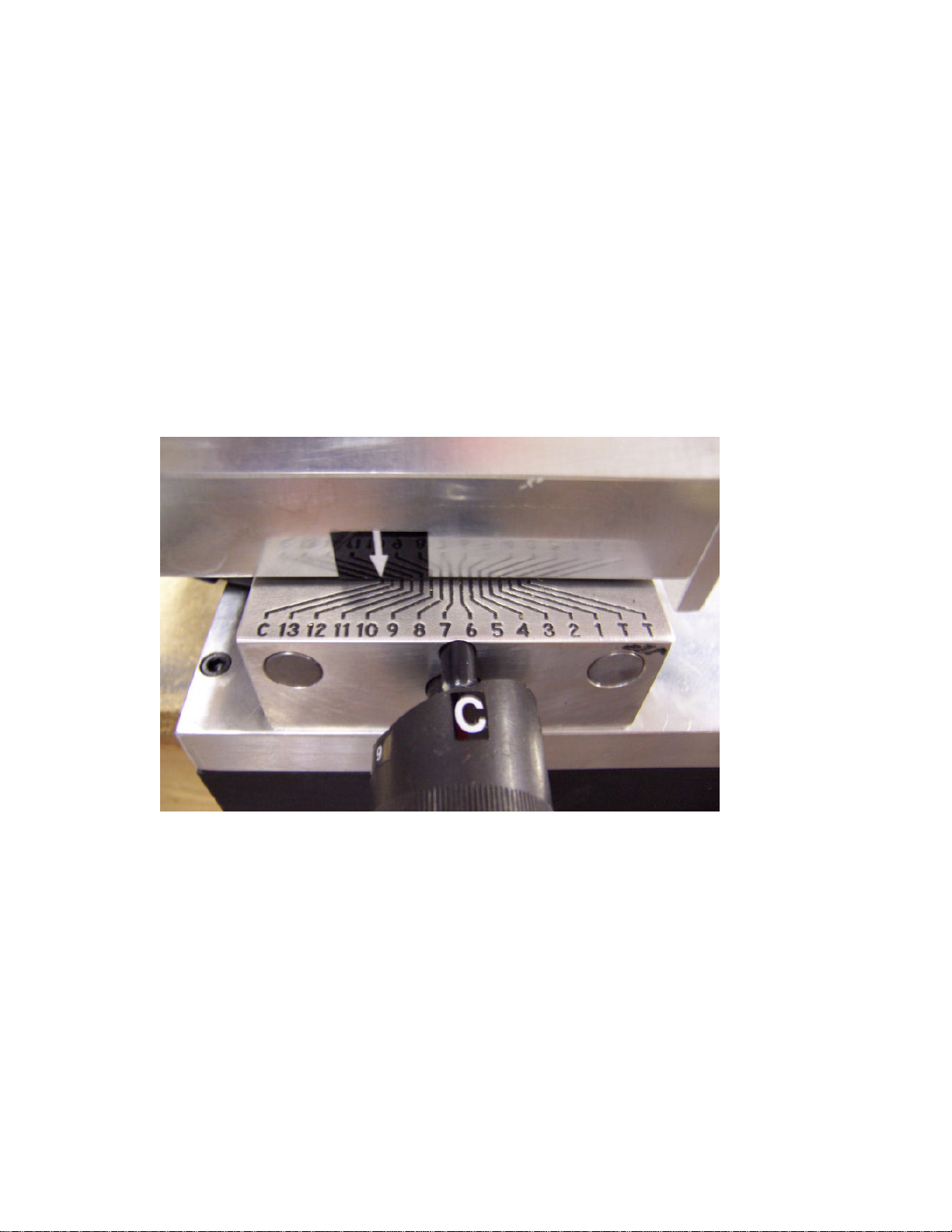
To adjust the spacing on the KX-1, insert an original key into the vise. Turn the spacing cam to the
first position and set the depth cam to the proper depth of the first cut on the original key. Use the
feed handle to move the key into the cutter and determine if the carriage needs to be moved to the left
or the right.
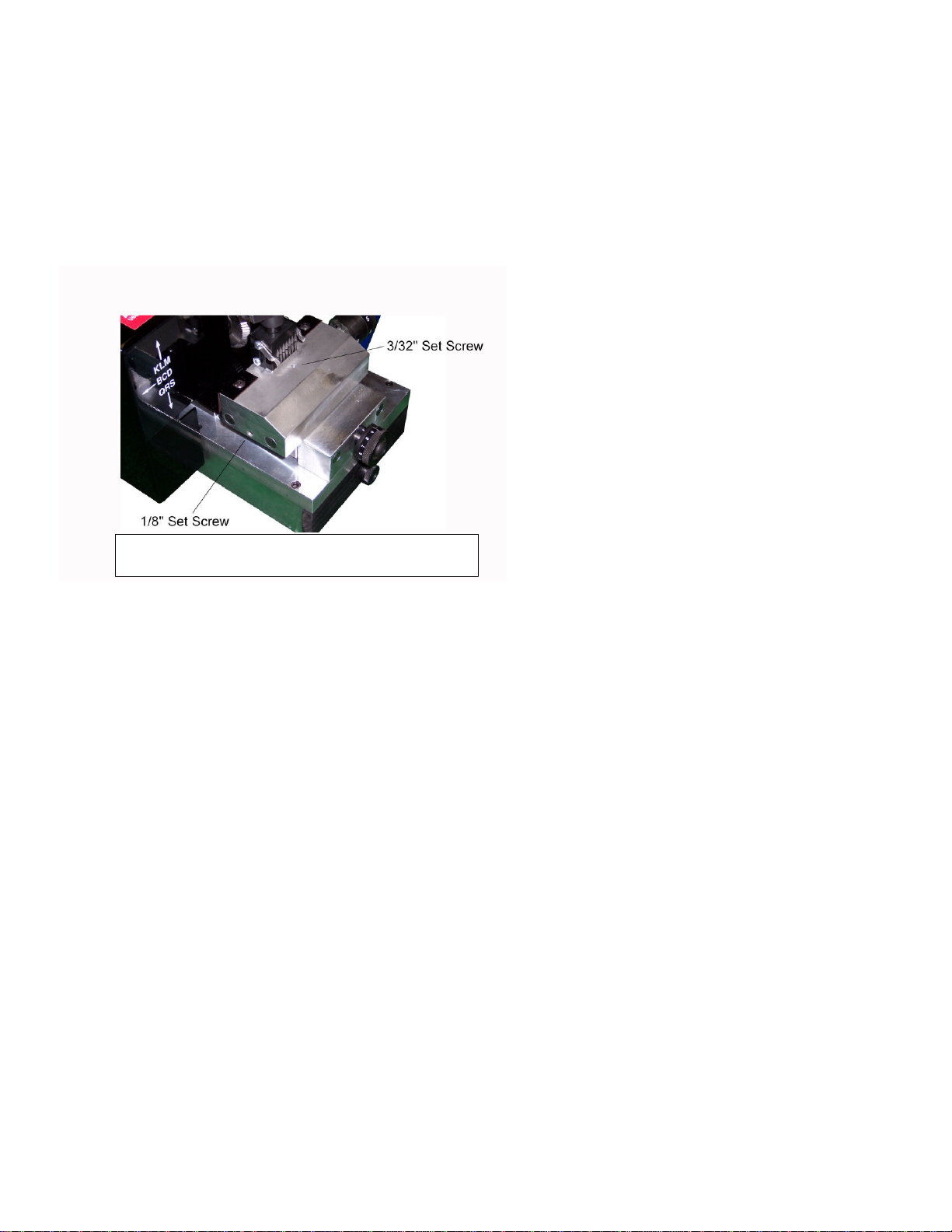
Slide the carriage to the right as far as it
will go (by hand). With the carriage in
this position, a setscrew will be
accessible thru the small hole located
just behind the key vise (see Figure 3).
Using the 3/32” Allen wrench, loosen
the setscrew. Next, using the 1/8” Allen
wrench, remove the setscrew located on
the left side of the carriage (See figure
3). Insert a flat screwdriver into this
hole (about 3 inches) and turn the screw
clockwise to move the vise to the right
of the cutter. Turn the screwdriver
counterclockwise to move the vise to
the left of the cutter. Once you have set the proper spacing, remove the screwdriver from the carriage
and replace the Allen screw. Re-tighten the setscrew by pushing the carriage all the way to the right
and inserting the 3/32” Allen wrench into the opening. Release pressure on the carriage.
TILTING SPINDLE ASSEMBLY
Your KX-1 has the ability to cut Medeco Commercial, Bi-Axial, and Emhart keys. To make angled
cuts, release the pressure on the spindle by loosening the lock rod located on top of the machine (the
lock rods are shipped inside the drawer, if you are not cutting Medeco you may choose not to install
them). Tilt the spindle by lowering or raising the tiltingspindle rod until it comes to a positive stop.
Re-tighten the tilting spindle lock rod and make your cuts for that angle. To save time, make all of the
center cuts first, then your left angle cuts, then the right angle. To re-center the spindle, loosen the tilt
spindle lock rod and move the tilt spindle rod to the center position, where you will feel a detent, and
tighten the tilting spindle lock rod.
MAINTENANCE
Very little maintenance is required on the KX-1. A slight touch of regular automotive grease on the
rod that contacts the space and depth cam will assure smooth operation of the cams. Teflon spray can
be used on the slide rods to keep them moving freely. The KX-1 uses sealed ball bearings in the
motor and spindle, which require no maintenance whatsoever.
Figure 3: Location of setscrews

WARRANTY
The KX-1, like all other Framon key machines, comes with a one-year, parts, labor and freight warranty. If
you have any problem with your KX-1 within the first year, contact Framon Manufacturing at (989) 354-5623.
We will issue a call tag for the machine, repair or replace the machine, and return it to you without any charge.
Repairs are completed within 2 working days from the day we receive the machine. After the first year, you
will be charged a flat labor fee, freight, plus any partsneeded to complete the repair.
KX-1 Application Chart
MANUFACTURER SPACE CAM DEPTH CAM CUTTER VISE SUFFIX
Arrow 1 S FC9045 1 AR
Assa 2 A FC9032 4 AS
Assa MK “0” 2A0 AM FC10416 4 AM
Best A-2 13 P FC9054 2 B2
Best A-3 13 N FC9054 2 B3
Best A-4 13 M FC9054 2 B4
Corbin D,H,Z Sys 70 3 B FC9054 1 CD
Corbin K,N Sys 70 3 D FC9054 1 CK
Corbin X Sys 70 12 E FC9054 1 CX
Corbin X Pre 70 12 CX FC9054 1 CXP70
Corbin GH 4 X FC9090 1 KW
Corbin 981 3 Y FC9054 1 C9
Corbin Z Pre 70 3 Z FC9054 1 ZC
Emhart 3 F FC8615 1 EM
Falcon Standard 7 R FC9090 1 FS
Falcon I-Core 13 P FC9054 2 FI
Grundman 16 G FC9051 1 GR
Kaba Peaks 140 15 P FC9054 2 K4
Kaba Peaks 150 13 P FC9054 2 K5
Kwikset 4 X FC9090 1 KW
Kwikset Titan 14 X FC9090* 1 KT
Lockwood 20 U FC9045 1 LK
Master 9 L FC9045 1 MS
Medeco Bi-Axial 6 T FC8615 1 MB
Medeco Commercial 5 V FC8615 1 MC
Medeco KeyMark 13 W FC9054 3 MK
Ruko 19 A FC9032 4 RK
Sargent C,R,L 10 J FC7863 1 SR
Sargent U,R,K,G,T,UT 10 H FC7863 1 SU
Schlage (incl. Primus) 8 C FC10031 2 SC
Schlage SFIC 18 P FC9054 2 ST
Weiser 7 R FC9090 1 WE
Yale Pro-Key 22 O FC9045 1 YP
Yale Standard 11 K FC9045 1 YA
* Kwikset Titan models are shipped with the FC9090 cutter. A separate charge (included upon request only)
will be added for the FC4590T cutter for making the firstcut next to the shoulder of the key, which has a 90
degree angle at the bow side.

Instructions For Cutting Southern Steel 13 Cut Keys
After reading your instruction manual for your KX-1 machine, there are a few differences in the
operation of the machine for 13 cut keys.
The depth cam shown below operates in the same way that the manual shows. Simply turn the cam to
the desired depth and feed the key into the cutter. The cam does have one special cut labeled “C”, for
Clearing Cut.
Above the depth cam is the spacing plate. Instead of having the cut labels on the cam, the spacing
plate and arrow will show in which position the carriage is. The key has 13 cuts, and the carriage will
detent to a stop in these positions. In addition, the carriage will also stop at the two positions marked
with a “T” and the last position marked with a “C”. In all three positions, you should turn the depth
cam to the “C” position and make a cut. These are clearing/relief cuts so that the blank will operate
properly in the lock and are just as important to the operation of the key as the other 13 cuts are.
The machine also requires a special cutting wheel, part numberDBC1085S. Be sure when replacing
the cutter that the teeth on the cutter are pointing downward.
The key is to be loaded into the machine with the tip of the key to the left and bow of the key to the
right. Use the bottom shoulder of the blank to stop the key.
If you have any questions, contact Framon Manufacturing Company at 989-354-5623 or Southern
Folger Detention.

RR Brink and Folger Adam Users
Along with this manual, you should also have received a single or two-page addendum regarding
specifics for your detention keys. We do not publish this information in this manual due to the
sensitive depth and space information included with it. If you lose the addendum, you will need to
contact us at 989-354-5623 with the serial number of your machine to receive it. We will also need to
know the location that the machine is being used in, which must match our records before it will be
released.
Parts Diagram
Table of contents
Popular Lathe manuals by other brands

Scheppach
Scheppach Lata 7.0v Translation from the original instruction manual

Cassese
Cassese Mach 4 UNI user & parts manual

CLAUSING
CLAUSING 1300 Series Instructions and parts manual

Rikon Power Tools
Rikon Power Tools 70-1420VSR Operator's manual

Promac
Promac GH-1640ZX operating instructions

Haas
Haas EC-400 Replacement