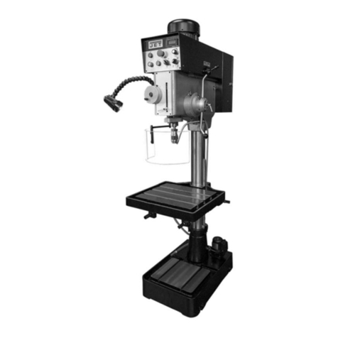
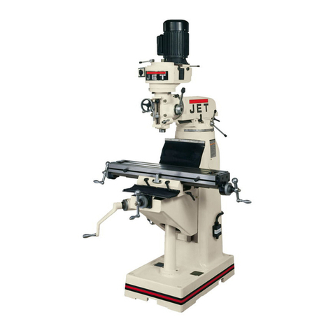
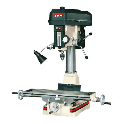
Jet JTM-1050EVS User manual

.JET
EQUIPMENT& TOOLS
OPERATOR'S MANUAL
JTM-1050EVS
~~
/.
JET EQUIPMENT & TOOLS, INC.
A WMH Company P.D.BOX 1349
Auburn, WA 98071-1349 253-351-6000
Fax253-939-8001
M-690060 2/2001

Important Information
1-YEAR
LIMITED WARRANTY JET offers a one-year limited
warranty on this product
REPLACEMENT PARTS
Replacement parts for this tool are availabledirectlyform JET Equipment& Tools.
To place an order, call 1-800-274-6848. Pleasehavethe followinginformation ready:
1. Visa, MasterCard,or DiscoverCard number
2. Expirationdate
3. Part number listedwithin this manual
4. Shipping address other than a PostOffice box.
REPLACEMENT PART WARRANTY
JET Equipment & Tools makes every effort to assure that parts meet high quality and durability
standards and warrants to the original retail consumer/purchaser of our parts that each such
part(s) to be free from defects in materials and workmanshipfor a period of thirty (30) days from
the date of purchase.
PROOF OF PURCHASE
Please retain your dated sales receiptas proofof purchaseto validate the warranty period.
LIMITED TOOL AND EQUIPMENT WARRANTY
JET makes every effort to assure that its products meet high quality and durability standards and warrants
to the original retail consumer/purchaser of our productsthat each product be free from defects in materials
and workmanship as follows: 1YEAR LIMITEDWARRANTY ON THIS JET PRODUCT. Warranty does not
apply to defects due directly or indirectly to misuse, abuse, negligence or accidents, repairs or alterations
outside our facilities or to a lack of maintenance. JET LIMITS ALL IMPLIED WARRANTIES TO THE
PERIOD SPECIFIED ABOVE FROM THE DATE THE PRODUCT WAS PURCHASED AT RETAIL.
EXCEPT AS STATED HEREIN, ANY IMPLIEDWARRANTIES OR MECHANTABILITYAND FITNESS ARE
EXCLUDED. SOME STATES DO NOT ALLOW LIMITATIONS ON HOW LONG THE IMPLIED
WARRANTY LASTS, SO THE ABOVE LIMITATION MAY NOT APPLY TO YOU. JET SHALL IN NO
EVENT BE LIABLE FOR DEATH, INJURIES TO PERSONS OR PROPERY OR FOR INCIDENTAL,
CONTINGENT, SPECIAL OR CONSEQUENTIAL DAMAGES ARISING FROM THE USE OF OUR
PRODUCTS. SOME STATES DO NOT ALLOW THE EXCLUSIONOR LIMITATION OF INCIDENTAL OR
CONSEQUENTIAL DAMAGES, SO THE ABOVE LIMITATION OR EXCLUSION MAY NOT APPLY TO
YOU. To take advantage of this warranty, the product or part must be returned for examination, postage
prepaid, to an authorized service station designated by our Auburn office. Proof of purchase date and an
explanation of the complaint must accompany the merchandise. If our inspection discloses a defect, JET
will either repair or replace the product or refund the purchase price, if we cannot readily and quickly
provide a repair or replacement, if you arewilling to accept such refund. JET will return repaired product or
replacement at JET's expense, but if it is determined there is no defect, or that the defect resulted from
causes not within the scope of JET's warranty, then the user must bear the cost of storing and returning the
product. This warranty gives you specific legal rights, and you have other rights, which vary, from state to
state.
JET Equipment &Tools. P.O. Box 1349,Auburn, WA 98071-1349 .(253) 351-6000

it WARNING
1. Read and understandthe entire
instruction manual before attempting set-
up or operation of this machine.
2. Always wear approved safety glasses/face
shieldswhile usingthis machine.
3. Make certain the machine is properly
grounded.
4. Before operating the machine, remove tie,
rings, watches, other jewelry, and roll up
sleeves above the elbows. Remove all
loose clothing and confine long hair. Do not
wear gloves.
5. Keepthe floor aroundthe machineclean
and free of scrap material,oil and grease.
6. Keep machine guards in place at all times
when the machine is in use. If removed for
maintenance purposes, use extreme caution
and replace the guards immediately.
7. Do not over reach. Maintaina balanced
stance at all times so that you do not fall or
lean against bladesor other movingparts.
8. Make all machineadjustmentsor
maintenancewith the machineunplugged
from the power source.
9. Usethe right tool. Don'tforce a tool or
attachmentto do ajob that it was not
designed for.
10. Replace warning labels if they become
obscured or removed.
11. Make certain the motor switch is in the OFF
position before connecting the machine to
the power supply.
12. Give your work undivided attention. Looking
around, carrying on a conversation, and
"horse-play" are careless acts that can result
in serious injury.
13. Keep visitors a safe distance from the work
area.
14. Use recommended accessories; improper
accessories may be hazardous.
15. Keep hands away from all moving parts
(belts, cutters, gears, etc.).
16. Never operate this machine under the
influence of alcohol or drugs.
17. Some coolants used for machining contain
chemicals that may be hazardous to your
health if not used properly. Read and
understand all user information listed on the
coolant container and protect yourself
accordingly.
18. Read and understand all warnings posted on
the machine.
19. This manual is intended to familiarize you
with the technical aspects of this milling
machine. It is not, nor was it intended to be,
a training manual.
20. This machine is designed and intended for
use by properly trained and experienced
personnel only. If you are not familiar with
the proper safe use of milling machines, do
not use this machine until proper training
and knowledge has been obtained.
21. Failure to comply with all of these warnings
may cause serious injury.
22. WARNING: Some dust created by power
sanding, sawing, grinding, drilling and other
construction activities contains chemicals
known to cause cancer, birth defects of other
reproductive harm.
Some examples of these chemicals are:
.Lead from lead based paint
crystalline silica from bricks and cement
and other masonry products, and
arsenic and chromium from chemically-
treated lumber.
.
.
23. Your risk from those exposures varies,
depending on how often you do this type of
work. To reduce your exposure to these
chemicals: work in a well ventilated area,
and work with approved safety equipment,
such as those dust masks that are specifically
designed to filter out microscopic particles
The JTM-1050EVS mill is pre-wired from the
factory. Stock Number 690060 is Pre-wired
230V. Stock Number 690062 is Pre-wired
460V. This machine is not dual voltage.
Specifications JTM-1050EVS
Stock Number (230V only) ... ... ... ....690060
Stock Number (460V only). ... ... ... .690062
Spindle Taper R-8
Diameter of Quill 3 3/8"
Number of Spindle Speeds Variable
Range of Spindle Speeds 10to 3,600 RPM
Downfeeds of Spindle (per/rev/in) ,0015", .003", .006"
Spindle Travel 5"
Head Movement 900Land R
.450F and B
Distance Spindle to Table 19"
Distance Spindle to Column 26 1/2"
Distance Spindle to Column 6"
Collet Capacity ...... ... ... 1/8"- 7/8"
Table Size ... 10"x 50"
LongitudinalTable TraveL 35"
Cross Travel 16"
Number of T-Slots & Size 3 & 5/8"
T-Slot Centers 2-1/2"
MaximumTable Load 720 Lbs.
KneeTraveL 16-1/2"
Overarm Travel 21 1/4"
Overall Dimensions 95 3/4"W x 70 5/8"D x 88-3/4"H
Motor 3 HP, 3Ph., Pre-wired230V or 460V
Net Weight (approx.) 3000 Lbs.
Shipping Weight 3050 Lbs.
Table of Contents
Warranty ......................
Warnings 1
Specifications 2
Table of Contents 2
Installation Layout.. ... ... ... ... ...... 3
Shipping Container Contents 4
Unpacking and Clean-Up 4
Site Preparation ... 4
Lifting the Mill 5
Lubrication 5
Electrical Connections ...6
Controls 6-8
Operating Precautions ............... ... ... 9
Setting Upfor Fine Hand Feed "9
Setting Up for Automatic Feed 10
Adjustments 10-11
Parts Lists and Breakdowns 12-27
WiringDiagram.. ...... ... ......,... ......... ... ... ..28:2 9
The specifications in this manual are given as general informationand are not binding. Jet Equipment and Tools reserve
the right to effect, at any time andwithout priornotice,changes or alterationsto parts, fittings, and accessory equipment
deemed necessary for any reason.
2

IN
(J1
IN
I
'-J
to;: "--.
VJ
"--.
-t:>-~
Q)
JTM-1050 EVS Installation Layout
24"
20 1/2"
'-J
'-b
r-
~!
c:::=8 I
.L__-
--,~
II ~
I ~
J .
5/8" Diameter
Hold Down Bolt
19 3/4"
96 1/ 4"
Fig. 1
3

Shipping Container Contents
1
1
1
1
Mill
FlatWay Cover (rear)
Accordion Way Cover (front)
Tool Box:
1 Hex Wrench Set (1.5 - 10mm)
1 19mm CombinationWrench
1 #2 Cross PointScrew Driver
1 #2 Flat BladeScrew Driver
1 Plastic Oil Can
1 Operator's Manual
1 Warranty Card
1 Eye Bolt
,-----.
L
.~
,2~
.
~~-
t.
..
-'.'.. jET
i. ~
.
"
.--. ~ ~
--~.",.-
'W' -. .
Unpacking and Clean-Up
.
1. Finish removing the sides and top of the crate.
Leave the mill bolted to the skid untilit is ready
to move to its final location.
2. Clean all rust protectedsurfaceswith kerosene
or a light solvent. Do not use gasoline,paint
thinner, or lacquer thinner. These will damage
painted surfaces. J
3. Cover all machined surfaces with a film of light
machine tool oil to inhibit rust. Fig.1
Site Preparation
it. Caution
Mill must be supported equally under all four
comers. Failureto comply may cause the
column to twist and put a bind in the bedways.
The mill must be placed on an even surfaceand
bolted to the floor. Anchor bolts of sufficient size and
length must be fastened to the floor accordingto the
footprint of the mill. See Fig. 1.
4

Lifting the Mill
The method for liftingthe mill is with a hookthrough
the eye bolt (A, Fig. 2) screwed intothe tapped hole
on the ram. Steady the millto prevent it from
spinning.
Note: Tighten ram locking bolts (8, Fig.2) before
lifting.
Carefully lift the mill and move to a positionover the
anchor bolts. Lower the mill over the anchor bolts,
check for level, and securewith washers and anchor
bolt nuts.
Check the millfor level with a machinist'slevel
placed on the table. Mill must be level back to front
and side to side. Shim if necessary, butremember
that the mill must be supported equallyat all four
corners. Check for level beforetighteningthe anchor
bolt nuts and after tighteningthem. Adjust as
necessary.
Note: The JTM-1050EVS pictured in figure2 shows
DRO, and POWERFEEDoptionalaccessories
available through JET.
Lubrication
Caution
Do not shift High-Low Gearwhile motor is
running. Rotatethe spindle by handto facilitate
changing leverpositions.
Spindle Bearings - (A, Fig. 3) fill oil cup once daily
with 1OW-machineoil.
Oil Pump - (C, Fig. 2) fill reservoiras neededby
removing cap on top of tank and fillingwith 10W
machine oil. Pump oil with release handleoncefor
every hour of operation. Way surfaces and
leadscrews are lubricated in this manner.
Knee Leadscrew - (D, Fig. 2) lubricatewith #2 tube
grease once weekly.
A~/ _ai
I
"
~
Fig.2
5Fig.3

Electrical Connections
it WARNING
A qualified electrician must make all electrical
connections!
Failure to comply may cause serious injury!
The JTM-1050EVS mill is pre-wired from the
factory. Stock Number 690060 is Pre-wired 230V.
Stock Number 690062 is Pre-wired 460V. This
machine is not dual voltage.
Confirm power at the site matches power
requirements of the mill beforeconnectingto the
power source.
The mill must be properlygrounded.
Controls
A. Spindle Brake (A, Fig.4) - locatedon leftside of
the head. Move in either directionto stop
spindle once power has beenturned off.
B. High-Neutral-Low Lever (B, Fig. 5) - locatedon
the right side of the head. Upper positionis high
speed (direct drive). Middle positionis neutral.
Lower position is low speed (back gear).
Caution
Do not shift High-Low Gearwhile motor is
running. Rotatethe spindle by handto facilitate
changing lever positions.
C. Power Feed Transmission Engagement
Crank (C, Fig. 5) - locatedon the rightside of
the head. When lever is in the right-handside
hole, the power feed worm gear is disengaged.
To engage power feed, pull knobout and move
lever around to the left-hand side. Releasethe
pin into the hole.
Fig.4
I
.!8
~WJI
6Fig.S

Caution
Engage gently to avoid damage to the worm
gear.
Powerfeed may be engaged when spindle is
rotating, however,it must be engaged gently to
avoid damageto the worm gear.
Do not use powerfeed at speeds above 3000
R.P.M
It is recommendedthat the powerfeed worm
gear be disengagedwhenever the power feed is
not required.This avoids unnecessarywear on
the worm gear.
D. Quill Feed Handle (D, Fig.6) - locatedon right
side of head. Rotate clockwiseto lower spindle.
Return springwill retractthe spindle
automatically once the handle is released.
E. Quill Lock (E, Fig. 6) - locatedon the right side
of the head. Rotatethe handleclockwiseto lock
the quill in a desired position. Rotatethe handle
counter-clockwise to release.
F. Micrometer Adjusting Nut (F, Fig.6), - located
on the front of the head. Use for setting specific
spindle depth.
G. Feed Control Lever (G, Fig. 6) - locatedonthe
left side of the head. Engagesoverloadclutch
on pinion shaft when positionedto the left. Stays
engaged until quill stop comes in contactwith
micrometer adjusting nut (forcingfeed control
lever to drop out automatically),or until lever is
released manually by engaging leverto the right.
H. Manual Feed (H, Fig. 6) - locatedon the left side
of the head. Feed reversing knob (I, Fig. 5) must
be in the neutral position. The feed control lever
(G, Fig. 5) must be engaged.
Note: manual feed handle and handwheelmay
be taken off when not in use.
I. Feed Reversing Knob (f, Fig.6) - locatedin
center of manualfeed handwheel. Positionof
the handle depends upon the directionof spindle
rotation. If boring with right hand cutting tools,
pull feed handle towards operator untilclutch
becomes engaged. Neutral positionis between
forward and reverse position.
7
~f
~--
A..",/
:'~
D
.'P'"
G
Fig.6

Caution
It Isrecommendedthatthe handlebeleftinthe
neutralpositionwhennotinuse.
J. Quill Stop (J, Fig. 7) - located on thefront of
head. Usedto disengagethe automaticfeed in
either direction as well as the setting pointfor
working to a given depth.
K. Quill Feed Speed Selector (K, Fig. 7) - located
on the left side of the head. Pullknobout and
locate handle over choice of three feed speeds -
1.5, .003, and .006thousandths perspindle
revolution. Feed is more readilyengagedwhen
spindle is turning.
L. Reversing Switch (L, Fig. 7) - locatedon the left
side of the head. Switches rotationof spindle.
M. RPM Gauge (M, Fig. 7) - locatedon the control
panel.
N. Coolant Switch (N, Fig. 7) - locatedon the
control panel. The switch is installedfor optional
coolant pump. The wiring must be hookedto
U2,V2, and W2 in the terminal strip.
0. Power Lamp (0, Fig. 7) - locatedon the control
panel.
P. Low/High Switch (P, Fig. 7) - locatedon the
control panel.
Q. Spindle Switch (Q, Fig. 7) - locatedon the
control panel.
R. Power Feed (R, Fig. 7) - locatedon the control
panel. The switch is installedfor optionalpower
feed. The wiring must be hookedto 11OV,OV in
the terminal strip.
S. Emergency Stop Switch (S, Fig.7) - locatedon
the control panel.
8
K
\
Fig.7

Operation
Operating Precautions
1. Be certain the spindle brake is released before
starting the motor.
2. Rotate the spindle by handto facilitate meshing
of the clutch and gears.
3. Do not use the quill powerfeed at speeds above
3000 RPM.
4. It is recommended that the power feed worm
gear be disengaged whenever the powerfeed is
not required. This will avoid unnecessarywear
on the worm gear.
5. The powerfeed can be used for drills up to 3/8"
in diameter (in mild steel). Use manualfeed for
drills larger than 3/8".
6. Overload clutch isfactory set to hold upto 200
Ibs. down feed pressureon the quill
(accommodates drills upto 3/8").
Do not attempt to adjust clutch pressure.
Setting Up for Fine Hand Feed
1. Disengage power feed by pullingout knob (A,
Fig. 8) and moving leverto the right hole.
2. Locate the feed reversing knob (C, Fig. 8 & 9) in
the center or neutral position.
3. Engage feed control lever (B, Fig.8) by pulling
away from the head assembly.
9
..'
Engage"'-- .
,On
Fig.S
Neutral
c
Fig.9

Setting Up for Automatic Feed
1. Ensure quill lock (D, Fig. 8) is off by rotating
counter-clockwise.
2. Set micrometer dial (E, Fig. 8) to desireddepth.
3. Engage power feed lever (A, Fig. 8) by pulling
out lock knob and moving leverto the left hole.
4. Selectfeed rate (F, Fig.8).
5. Selectfeed direction (C, Fig. 8 & 9).
6. Engagefeed trip lever (8, Fig. 8) by pullingaway
from head assembly.
Adjustments
Feed Trip Adjustment
1. Loosen locknut (A, Fig. 10).
2. Engagetrip handle (C, Fig. 10)by pullingaway
from head assembly.
3. Adjust micro nuts (E, Fig. 10)againstquillstop
(8, Fig. 10).
4. Slowlyturn adjusting screw (D, Fig. 10)until
lever (C, Fig. 10)trips.
5. Tighten locknut (A, Fig. 10).
...
Engage~ .
,On
Fig.8
Neutral
c
Fig.9
/B
2
4-E
5
\ \
\ \
\,
)'- "
()
\. _/ 0
10 DA
Fig.10

Knee Gib Adjustment
Note: when adjusting the gibs for the knee, the
saddle and the table. Always start with the knee
first. Adjust the saddle second, and adjust the
table last.
Adjust gib screws through wiper on eitherside of the
knee where it meets the column.
Saddle Adjustment
Adjust gib screw found on the left front side of the
carriage.
Table Adjustment
Adjust gib screws found on the sides of the table
toward the front of the carriage.
Head Alignment
The scales on the ram adapter and headrotationare
guides only. Close tolerance work will require the
use of a dial indicatorto make surethe headis 90°
to the table in the X and Y-axis. Please notethe
table is fitted to be slightly higher inthe front, usually
about .0005".
Delta Variable Frequency Drive
Please refer to your Delta manual for any
questions concerning this unit.
Note: This drive is not dual voltage.
11

PartsListfortheJTM-1050EVSTurretMill
Inverter Speed Head Assembly
Index Part
No. No. Description Size Qty.
1 PVS-082 Housing 1
2 TS-1503051 HexSocket Cap Screw M6*20 6
3 PVS-087 Gear Shaft Pinion 1
4 ... PVS-089 ... Detent Plate...... ......... ... ...... 1
5 PVS-090 BearingStop 1
6 PVS-091 Spring 1
7 TS-1503011 HexSocket Cap Screw M5*14 3
8 PVS-092 PinionBlock 1
9 PVS-094 PinionCrank " 1
10 PVS-099 Plastic Ball 1
11 IVS-011 SpringPin 3*20 1
12 TS-1502041 Hex SocketCap Screw M5*16 3
13 BB-620322 BallBearing 620322 2
14 KEY5518 Key 5*5*18 1
15 KEY5515 Key 5*5*15 1
16 PVS-067 CounterShaft 1
17 TS-1523011 Set Screw M6*6 1
18 PVS-066 BullGear 1
19 PVS-064 BearingHousing 1
20 TS-1502051 HexSocket Cap Screw M5*20 3
21 PVS-084 , Spring 3
22 PVS-102 SpringShaft 3
23 PVS-081 Nut " 1
24 PVS-109 LockWasher 1
25 PVS-103 Washer 1
26 PVS-080 " Snap Ring C-62 1
27 BB-690822 BallBearing 690822 2
28 PVS-079 BearingWasher 1
29 PVS-078 BearingWasher 1
30 ...PVS-076 ...... ......Washer ..... ............ ... 1
31 PVS-075 Rack Cup 1
32 PVS-063 Timing Belt 225L100 1
33 PVS-074 Gear 1
34 PVS-062 Timing BeltPulley 1
35 IVS-035 SpringWasher 5/8" 1
36 PVS-061 Nut " 5/8"-18NF 1
37 KEY8712 " Key 8*7*12 1
38 PVS-073 SpindleGear Hub 1
39 PVS-100 Collar 1
40 KEY7740 Key 7*7*40 1
41 4VS-H003 SpindlePulley Hub 1
42 ...IVS-042 ,...Collar , 1
43 PVS-050 LowerHousingCover 1
44 TS-1503051 Hex SocketCap Screw M6*20 4
45 TS-1523011 Set Screw " M6*6 1
46 IVS-046 , SnapRing S-8 1
47 PVS-059 BrakeStud 2
48 PVS-047 ". Brake Lining " " 1
12

49 PVS-058 Brake FingerPivotStud 1
50 . PVS-099. ... Plastic Ball ...... ... ...... 2
51 IVS-051 RoundHeadScrew 4
52 IVS-052 ,..Snap Ring S-12 1
53 PVS-052 BrakeShaftSleeve 1
54 PVS-053 Brake Lock Shaft 1
55 TS-1503061 Hex Socket Cap Screw M6*25 1
56 PVS-054 Brake Lock Block 1
57 TS-1540041 Nut M6 1
58 PVS-048 , LockScrew 1
59 TS-1502041 HexSocket Cap Screw M5*16 1
60 BB-6010ZZ BallBearing " 6010ZZ 1
61 .. PVS-046 ...... BearingCover.. ... 1
62 PVS-049 BrakeSpring 2
63 TS-1502031 HexSocket Cap Screw M5*12 2
64 :IVS-064 .""""'''''''''''''''''''' Brake Ring " 1
65 4VS-002 Pulley 1
66 .IVS-066 , Washer 1
67 IVS-067 Lock NuL 1
68 TS-1502051 HexSocket Cap Screw M5*20 3
69 PVS-011 Motor PulleyCover 1
70 ..IVS-070 Belt. "... 1
71 TS-1502041 HexSocket Cap Screw M5*16 6
72 1020-H071 Lock Ring " 1
73 1020-H070 Motor Pulley " 1
74 KEY10830 Key 10*8*30 1
75 PVS-101 ......... Cover ...... ... 2
76 IVS-076 RoundHeadScrew 8
77 ... PVS-001 Housing ... ... ... ...... .. ...1
78 SP-060 Block " 1
79 TS-1504051 Hex SocketCapScrew M8*25 3
80 IVS-080 SpringWasher M10 4
81 IVS-081 Hex SocketCap Screw M10*30 4
82 IVS-082 InverterMotor 3HP/4P 1
83 BB-6007ZZ BallBearing 6007ZZ 1
84 PVS-013 Cover......... ... ... ... ... 1
85 TS-1502041 Hex SocketCap Screw M5*16 3
86 PVS-115 DrawBarWasher " 1
87 PVS-114 DrawBar 1
88 TS-1503021 Hex SocketCap Screw M6*10 4
89 4VSE187 Operation Box 1
90 IVS-090 R.P.MIndicator 1
91 4VSE186 Operation Panel 1
92 IVS-092 '"'''''''''''''''''''''''''' RoundHeadScrew 6
13

Inverter Speed HeadAssembly
...
77
43

Head Assembly
1 TS-1503031 HexSocket Cap Screw M6*12 1
2 1050B-2.. ...... Washer ... ... ... ... ...1
3 1050B-3 Feed Bevel Pinion 1
4 1050B-4 Worm Gear Shaft Sleeve 1
5 1050B-5 Bushing 1
6 TS-1522011 Set Screw 1
8 1050B-8 Worm Gear 1
10 KEY3312 Key 3*3*12 1
12 TS-1504031 HexSocket Cap Screw M8*16 1
13 .. B-13. """"" .........Washer ... ...... ... ... 1
14 KEY3308 ...... ............Key. ... ... ... 3*3*8.. 2
15 B-15 BevelGear... ... ., 1
16 B-16 Feed EngagePin"""""""'"'''''''''''''''''''''''''''' 1
17 1050B-17 Worm Gear Cradle 1
18 B-18 Worm Gear CradleShaft 1
19 1050B-19 Shaft Sleeve 1
20 B-20 Gear Shaft Plunger 2
21 B-21 Spring 2
22 1050B-22 Spring Pin 3*20 2
23 B-23 ShiftCrank 2
24 B-24 BlackPlastic Ball 3
25 TS-1503010 HexSocket Cap Screw M5x12 3
27 B-27. ...... Bushing... ...... ... ... 1
28 B-28 Gear 1
29 KEY3345 Key 3*3*45 1
31 1050B-31 Gear Shaft"'"'''''''''''''''''''''''''''''''''''''''''''''''''' 1
32 1050B-32 Snap Ring S-16 1
33 1050B-33 BevelGear Bushing 1
34 . 1050B-34. ...... Spacer...... ... ............ ...1
36 .. 1050B-36.. .......Gear. ......... ...... ...... ... ... 1
39 TS-1540031 Nut M5 1
40 1050B-40 Feed Drive Gear 1
41 1050B-41 NeedleBearing 1
42 1050B-42.. ... Bushing... ............... ... 1
43 1050B-43 Worm Gear 1
44 B-44 Bushing ""' , 1
47 ""'''' B-47 Washer 1
48 B-48 Bushing 2
49 "'" ...B-49.. ... BevelGear ......... .................. .. 2
50 B-50 Feed ReverseClutch "'''''''''''''''''''''''''''''''' 1
54 TS-1503061 Hex SocketCap Screw M6*25 1
55 B-55 ReverseClutch Rod 1
56 B-56 Spring Pin 3*20 1
57 B-57 FeedWorm Shaft 1
58 TS-1523011 Set Screw M6*6 1
59 . 8-59 SpringPin 3*12 2
60 ... B-60. ...... Chip Guards....... ...... 1
61 TS-1522031 Set Screw M5*10 1
62 .. KEY3315. "'"'''''''''''''''' Key 3*3*15 2
63 B-63 FeedGear Shift Fork 1
64 B-64 Gear ShiftCrank 1
66 B-66 Cluster Gear Cover 1
15

67 TS-1502031 HexSocket Cap Screw M5*12 4
73 . TS-1502081 HexSocket Cap Screw M5*35 2
74 B-74 Clutch RingPin""'''''''''''''''''''''''''''''''''''''''''''' 2
75 B-75 Clutch Ring 1
76 TS-1523021 Set Screw """""'''''''''''''''''''''''''''''''''''''''''''''' M6*8 1
78 B-78 Clutch Locknut 1
79 B-79 SafetyClutchLocknut "'"'''' 1
80 B-80 Overload Clutch ""'''''''''''''''''''''''''''''' 1
81 B-81 Overload Clutch Sleeve ""'"'''''''''''''''''''''' 1
82 KEY5813""""'"'''''''''''''''' Key 5*8*13 1
83 B-83 HexSocket Head Bolt 3
85 TS-1523011 Set Screw ""'''''''''''''''''''''''''''''''''''''''''''''''''''' M6*6 2
86 B-86 Cross PlateScrew M4*16 4
88 B-88 Spring ...... 1
89 B-89 Spring Plunger '"'''''''''''''''''''''''''''''''''''''''''''''' "'''''''''''''''''''''''''''''''' 1
90 B-90 Bushing """'"'''' "'''''''''''''''' 1
92 B-92 Worm Gear '''''''''''''''''''''''''''''''''''''''''''''''''''''' 1
93 B-93 Clutch Ring ""' , 1
94 B-94.. , Snap Ring S-10 1
95 TS-1502051 Hex Socket Cap Screw M5*20 1
96 B-96 Clutch Trip Lever " "'''''''''''''''''''''''''''''''' 1
97 B-97 ....." Clutch Washer ".. 1
98 B-98 Snap Ring , S-10 .." 1
99 B-99.. Clutch Arm Cover "'''''''''''' 1
100 C-19-1 Set Screw M6*16 1
101 TS-1540041 Nut M6 1
102 B-102 Spring Pin 5*18 1
103 B-103 Cam Rod 1
104 B-104 Trip Handle " 1
106 B-106 Feed Trip Bracket "'''''''''''''''''''''''''''''''''''''''''' 1
107 TS-1503051 Hex Socket Cap Screw M6*20 1
108 TS-1523031 Set Screw M6*10 1
109 . KEY331 0 "... Key " 3*3*10 1
110 B-110 '"'''''''''''''''''''''' Knob Stud 1
111 B-111 Reverse Knob ""'"'''''''''''''''''''''''''''''''''''''''''' 1
112 B-112 E-Ring E-6 1
113 B-113 Handle Wheel Clutch 1
114'''''' B-114 Steel Ball 3/16" 2
115 B-115 Compression Spring ... ... 2
116 B-116 Set Screw ""'''''' M8*6 1
117 B-117 " Spring Pin 3*15 1
118 B-118 Cam Rod Sleeve 1
119 B-119 Spring Pin """"'''''''''''''''''''''''''''''''''''''''''''''''' 3*12 1
120 B-120 Compression Spring 1
121 B-121 Trip Plunger """"""",,"'"'''''''''''''''''''''''''''''''' 1
123 ..,...B-123 Bushing , " 4
124 B-124 Feed Trip Plunger " """'''''''''''''''''''''''''''' 1
125 B-125.. Handle Wheel , 1
126 B-126 Handle 1
127 B-127 , Spindle , , 1
128 B-128 Quill Skirt " 1
129 B-129 Locknut , 1
131 BB-6206ZZ Ball Bearing 6206ZZ 1
132 B-132 Nut , M4... 1
16

133 8-133 Nose Piece """"""""""""""""""""""""""" 1
134 8-134 , Spindle DirtShield 1
135 88-7207C Angular 8earing 7207 1
136 8-136 ... Spacer ... ... ... ... 1
137 8-137 Spacer ... 1
138 88-7207C Angular 8earing 7207 1
139 ......8-139 ... ... ......Set Screw .....,. ............ . 1
140 8-140 Set Screw ,1
141 TS-1523011 Set Screw M6*6 1
142 8-142 Quill.. .. 1
143 8-143 Spring Pin 3*16 1
144 8-144 Set Screw M4*20 1
145 8-145 Feed TripLever 1
146 8-146 TripLeverPin 1
147 8-147 IndicatorRod 1
148 8-148 QuillLockSleeve 1
149 8-149 LockHandle 1
150 8-150 RoundHead Screw M5*8 2
151 8-151 Washer M5 2
153 8-153 QuillLockSleeve 1
154 8-154 IndicatorRodScrew 1
155 8-155.. ... ... T-8olt ....... ... ...... 4
156 8-156 Spacer 4
157 B-157 Adapter NuL 4
158 8-158 Round Head Screw 2
159. 8-159... ... Micrometer Scale... ... ... ... ... 1
160 8-160 Snap Ring S-16 1
161 B-161 QuillMicro-StopNut 1
162 8-162 QuillMicro-StopNut 1
163 8-163 QuillStop Knob 1
164 8-164 QuillMicro-StopNuL 1
165 B-165 RoundHead Screw M10*15 1
166 8-166 QuillPinionShaft 1
168 8-168.. ... ... Pin...... ... ...... ... ... 1
169 TS-1503010 HexSocket Cap Screw M5*12 2
171 KEY3320 Key 3*3*20 1
172 8-172 PinionShaft HubScrew 1
173 8-173 Set Screw 5/16"*1/4" 1
174 8-174 Compression Spring 1
175 8-175 HandleHub 1
176 8-176 HubSleeve 1
177 B-177 SpringCover 1
178 B-178 ClockSpring 1
179 B-179 Washer 4
181 TS-1523041 Set Screw M6*12 2
183 B-183 Reverse Trip8all Lever 1
184 B-184 Reverse TripPlunger 1
185 B-185 TripBallLeverScrew 1
186 B-186 WormGear 1
187 KEY4418 Key""""""""""""""""""""""""""" 4*4*18 1
188 B-188 Set Screw 1
189 B-189 WormShaft 1
190 B-190 PinionShaft HubHandle 1
191 B-191 BlackPlasticBall 1
17

192 8-192 QuillHousing 1
193 8-193 Compression Spring 1
194 8-194 Snap Ring 8-30 1
195 8-195 8ush 1
196 T8-1523011 Set Screw M6*6 1
197 8-197 Nut 1
18
Table of contents
Other Jet Drill manuals

Jet
Jet JMD-40GHPF Service manual

Jet
Jet JAT-610 Application guide

Jet
Jet JMD-45VSPF Service manual

Jet
Jet JMD-18 User manual

Jet
Jet JAT-630 Application guide

Jet
Jet JMD-15 Service manual

Jet
Jet JDP20EVST-460-PDF Service manual

Jet
Jet JMD-45PF User manual

Jet
Jet JNS-4031 Service manual

Jet
Jet JAT-620 Application guide