JETI model ENLINK 2RS Plus User manual

User´s manual: Intelligent switch ENLINK 2RS Plus
-1-
User manual ENLINK 2RS Plus
1. Description
ENLINK 2RS Plus is a device used to maximize the security and reliability of remotely controlling
models. Any, even the most perfect devices that are serially connected to the system always reduce the
system’s reliability. Using a parallel connection for control systems that are otherwise separated from
each other has always been the most reliable approach. That is why the ENLINK 2RS Plus is designed
to ensure increased operational reliability and safety. The only serial component in such a system (when
excluding the transmitter) that potentially reduces the reliability of thy system is then the ENLIK 2RS
Plus. Even in the worst case scenario the ENLIK 2RS Plus can deteriorate only one controlled function
and not the whole system. If each servo in the model is connected via an ENLINK 2RS Plus, then
through the parallel connection of these RS Plus devices, the reliability increases significantly.
ENLINK 2RS Plus is basically an intelligent switch. It selects one of the two input signals and copies
it to the output. At the same time it combines two different power supplies with a common ground.
ENLINK 2RS Plus is mainly designed to be connected to the system using the parallel connection of
two receivers in the model (e.g. Duplex receiver and REX FM receiver, or two Duplex receivers, two
RSAT2 EX satellites). You can change a desired function of the ENLINK by a simple change of the
firmware version. The Servo firmware is used for sending servo positions, the PPM firmware is used
for sending the PPM signals. Use the USB Adapter to change the firmware, see chapter 5. Update and
changing PPM/Servo software version.
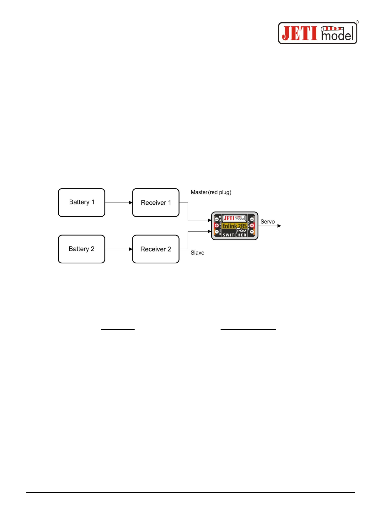
2. Connection
ENLINK 2RS Plus has two inputs that connect to outputs from the receivers. Part of ENLINK 2RS
Plus are power supply separating diodes that ensure the separation of the power supply for individual
receivers and thus prevents the mutual balancing of the power supply between the individual
receivers. The result is that the receivers do not have to be powered from one source, or in the case
of separate power supplies, the power sources do not have to be identical. E.g. it is possible to connect
User´s manual: Intelligent switch ENLINK 2RS Plus
-2-
one of the receivers to a 4xNiCd battery and the other to a 5xNiCd. The servo itself or the stabilization
unit is then supplied with power from the receiver which has the higher supply voltage. In this
example the servo is first supplied power from the 5xNiCd until the voltage of both batteries is equal.
Nevertheless, we recommend using the same two sets of batteries.
On the Master input (main receiver, red connector) the output from the main receiver is connected,
the output from the “back-up” receiver is connected to the Slave input (back-up receiver, black
connector).
ENLINK 2RS Plus has two outputs for connecting two JR style connectors. The connection of both
outputs is parallel. Thus, it is possible to connect e.g. two separate servos with the same function on
the output.
3. Version with Servo Output Firmware
ENLINK 2RS Plus eliminates signal losses from individual receivers. In case of a total loss of both
input signals, the ENLINK 2RS Plus switches to a preset mode.
For the correct function of the ENLINK 2RS Plus device it is necessary to have the receiver
being connected to MASTER labelled input set so that it does not generate any signal on its servo
outputs in case of signal loss (e.g. repeating the last known value or activating Fail Safe of the
receiver). If Fail Safe is required, it should only be set in the receiver connected to the ENLINK
input labeled SLAVE or directly in the ENLIK setup.
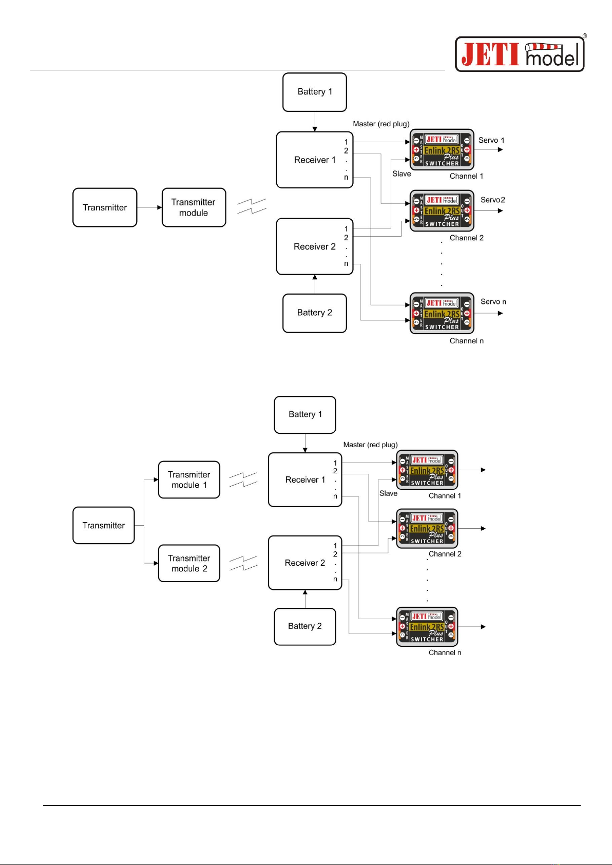
The selected channel must be identical for both receivers set and have the same function for both
receivers. It is advisable to use a system with digital data transfer (Duplex) as the main receiver.
When connecting the ENLINK 2RS Plus to two separate receivers, the correctness of the signal starts
to be continuously evaluated on both outputs of the receivers. If there is a valid signal on the Master´s
input, the ENLINK 2RS Plus prefers validity of this servo position and generates this signal unchanged
to the servo output. In case an incorrect signal on the Master´s input is detected, the ENLINK 2RS Plus
starts generating a signal from the Slave input to the servo output if this signal is valid. Otherwise, the
ENLINK 2RS Plus goes back to the default state (it turns off output servo impulses, repeats last valid
position or switches to Fail Safe).
User´s manual: Intelligent switch ENLINK 2RS Plus
-3-
It is possible to reach an even greater level of safety by using two transmitter modules (e.g. Duplex
or FM and Duplex) and two receivers.
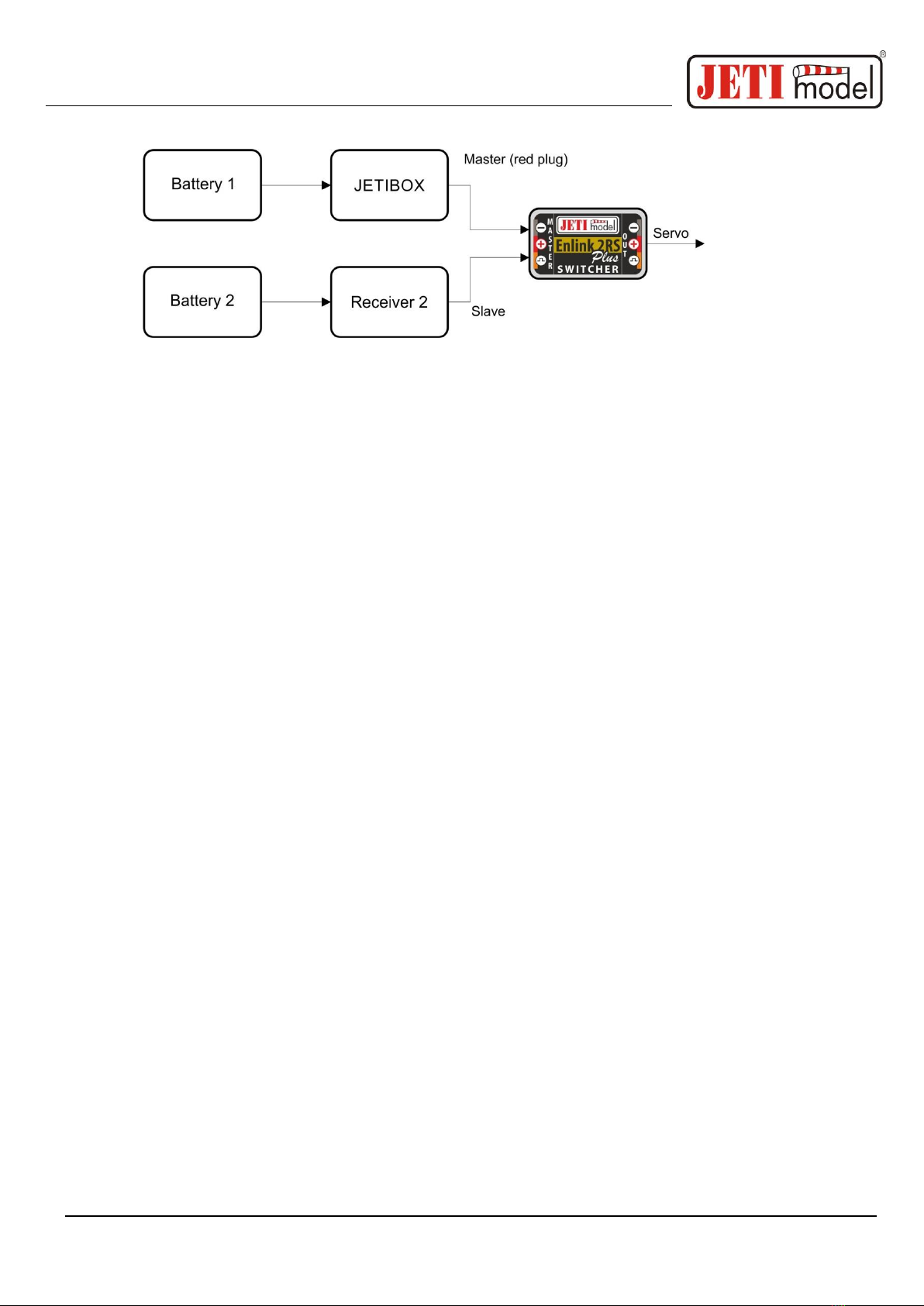
The JETIBOX terminal is used to set the parameters of the ENLINK 2RS Plus. The ENLINK´s three-
wire cable (red connector) with the JR style connector can be connected directly to the JETIBOX. Then
it is necessary to ensure power supply for the JETIBOX e.g. using a 4xNiCd battery. At the same time
it is possible to connect the Slave input not only the JETIBOX, but also servo impulses from one of
the receivers. Then you can connect a servo to the ENLINK output and check the actual servo position
on the JETIBOX:
User´s manual: Intelligent switch ENLINK 2RS Plus
-4-
3.1 Setting up the ENLINK 2RS Plus using the JETIBOX
ENLINK 2RS Plus can be used with no further setup. With a JETIBOX it is possible to change
parameters and settings in the ENLINK 2RS Plus. Using the JETIBOX also enables following the
statistics of input signal losses of the receiver that occurred during operation.
After connecting the ENLINK 2RS Plus to the JETIBOX the welcome screen is displayed. The first
line of the display contains identification of the device. In the second line, there is statistic data of the
backup (Slave) receiver failure. The first number, given as a percent, informs about the proportion of
the time the ENLIK 2RS Plus was switched to the Slave input relative to the total operation time since
the last reset. The second number, in the min:sec:thousanth format, indicates the longest recorded
period during which the ENLIK 2RS Plus was switched to the Slave due to incorrect signal on the
Master input. Both failure data sets are automatically deleted if both inputs are disconnected (i.e. power
supplies of the receivers are disconnected) and at the same time a valid signal on the Master input is
detected after switching on again.
Example of measured statistics: S 10.0% 00:05:569
The 10.0% value means that the ENLINK 2RS Plus was switch to the backup receiver during 10%
of the “flight time”. The 00:05:569 indicates that ENLINK 2RS Plus was switched to the backup
receiver for 5.569 seconds as the longest uninterrupted period.
Scroll between the menu items using the arrow up or down buttons (direction towards the welcome
screen). Carry out each menu setting using the left arrow and right arrow. The menu will gradually
show the following settings:
Reverse mode - allows you to reverse the output sensing (center = 1.5 ms).
Signal Fault - sets the action of the switch in the event of loss or invalid signal detection on both
inputs: repeat - repeats the last valid deflection, out off - output off after a preset delay, Fail Safe
- goes to the preset of output (Output Fail Safe) after a preset time delay.
Fail Safe Delay - indicates for how long the output will wait to switch to the preset for output or
the output is switched off when a lost or invalid signal is detected at both inputs.
Fail Safe Out - Setting of the output in the event a lost or invalid signal is detected at both inputs.
User´s manual: Intelligent switch ENLINK 2RS Plus
-5-
ATV High Limit - the maximum output limit.
ATV Low Limit –the minimum output limit.
Default Setting - pushing buttons on the right and left will reset all values to the factory settings.
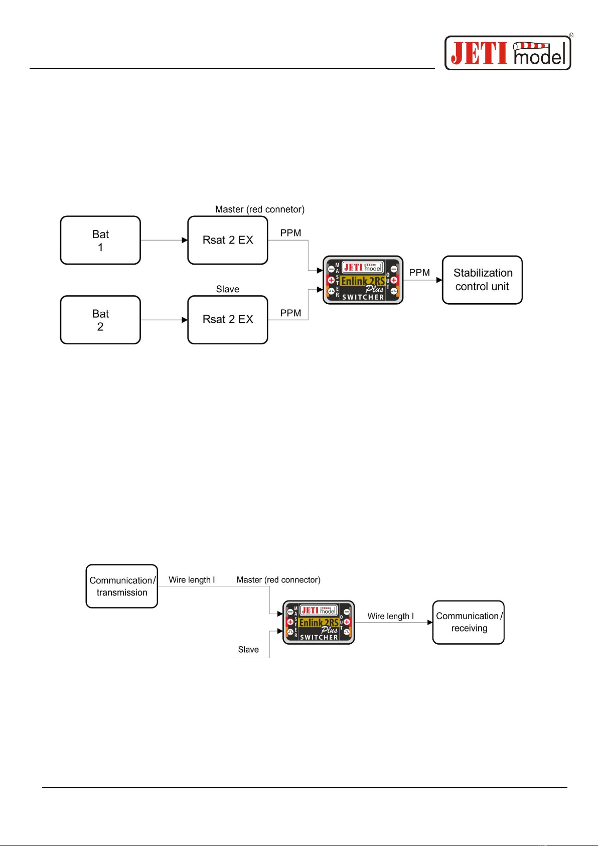
4. Version with PPM Output Firmware
ENLINK 2RS Plus with the PPM software is primarily used to transfer the PPM signal. The PPM
signal brought to one of the ENLIK inputs is copied to the output. ENLINK 2RS Plus checks if there
is signal on Master. If there is, it is immediately, without delay, copied to the output. If a signal loss
occurs on the Master, the ENLINK switches to Slave and starts copying signal from the Slave in case
there is any on its input. As soon as the signal is restored, the ENLINK switches back to copying the
Master signal.
In the version with the PPMfirmware, it is not possible to set theENLINK via JETIBOX terminal.
ENLINK 2RS Plus is even able to copy some types of communication (such as UDI, EX Bus) up to
the speed of 125kbps. Therefore, it can be used even in cases when it is necessary to use longer wiring
that can cause deterioration of the communication quality. The ENLINK 2RS Plus therefore functions
as a repeating device, where you just plug in one of the ENLIK 2RS Plus inputs.
The ENLINK 2RS Plus copies the signal unidirectionally, therefore it cannot be used to transmit the
two-way communication.

User´s manual: Intelligent switch ENLINK 2RS Plus
-6-
5. Update and changing PPM/Servo firmware version
The ENLINK 2RS Plus allows updating of its firmware via PC. Updating is done using the JETI USB
adapter.
Procedure:
oFind the program to update to the latest firmware on the manufacturer´s website under
„Downloads“. Save it to your computer.
oConnect the USB adapter to your computer. The procedure of installing the drivers for the
USB adapter is included in the USB adapter manual.
oRun the firmware update on your PC and select the firmware version –either PPM or Servo.
oConnect the USB adapter via the three-wire cable to the Master input of the ENLIK 2RS
Plus.
oAfter connecting the device the update will begin.
6. Technical data for the ENLINK 2RS Plus
Technical data:
ENLINK 2RS Plus
Recommended input voltage
5 –8.4 V
Maximum input voltage
16 V
Customize current consumption
Typ. 3.5mA
Output pulse current
12 A
Output constant current
3 A
Max. number of connected servos
2 pcs
Operating temperature
- 20°C up to +85°C
Weight
11 g
Dimensions
38 x 12 x 6.5 mm

User´s manual: Intelligent switch ENLINK 2RS Plus
-7-
7. Warranty
This product is covered by warranty for 24 months after the day of purchase provided that it has been
operated in accordance with these instructions at the specified voltage and is not mechanically
damaged. When claiming warranty repairs for the product, always attach a proof of purchase. Warranty
and post-warranty service is provided by your dealer or the manufacturer.
In case you are not sure about the setup or some functions of the product, do not hesitate to contact
our technical support. You can contact either your dealer, or directly the manufacturer JETI model
s.r.o.. For further information see our webpages www.jetimodel.cz.
The manufacturer: JETI model s.r.o. Příbor, www.jetimodel.cz

User´s manual: Intelligent switch ENLINK 2RS Plus
-8-
8. ENLINK 2RS Plus menu diagram for the Servo firmware
version
This manual suits for next models
1
Table of contents
Other JETI model Switch manuals


