Jeti Duplex DC-24 User manual

computer radio control system EN
DC/DS-24
2.4GHz/900MHz
Dual Band System
ENFW 4.10
CZECH REPUBLIC

computer radio control system EN
1. Introduction ........................................................................................... 07
1.1 DC/DS .................................................................................................07
1.2 Features ............................................................................................. 07
1.3 Manual Navigation ........................................................................ 09
1.4 Technical Support ........................................................................... 09
1.6 DC-24 Package Contents ............................................................... 10
1.7 DS-24 Package Contents ............................................................... 10
2. System Specifications .......................................................................... 11
3. Description of Transmitter DC-24 ................................................... 12
3.1 Control Identification ................................................................... 12
3.2 Assembly Identification ................................................................ 13
3.3 Control Stick Assembly .................................................................. 14
3.3.1 Control Stick Length Adjustment ...................................... 14
3.3.2 Swivel Control Stick Adjustment ........................................ 14
3.3.3 Control Stick Tension Adjustment ..................................... 15
3.3.4 Ratchet Tension Adjustment .............................................. 15
3.3.5 Throttle stick travel adjustment ........................................ 16
3.3.6 Changing the transmitter mode ....................................... 16
3.3.7 Transmitter Gimbals with Switch or Button Installation
.................................................................................................... 17
3.4 Swappable and Assignable Switches ........................................ 19
3.5 Digital Trims .................................................................................... 20
3.6 Transmitter Battery Pack ............................................................... 21
3.6.1 Charging ............................................................................... 21
3.6.2 Battery Replacement .......................................................... 21
3.7 PPM Output Connector .......................................................... 22
3.8 Handling ..................................................................................... 22
3.9 Change SD Card .............................................................................. 23
4. Description of Transmitter DS-24 .................................................... 24
4.1 Control Identification ................................................................... 24
4.2 Assembly Identification ................................................................ 25
4.3 Control Stick Assembly .................................................................. 26
4.3.1 Control Stick Length Adjustment ...................................... 26
ver. 1.0 - 2016-07, FW ver. 4.1
1

computer radio control system EN
4.3.2 Control Stick Angle Adjustment ........................................ 26
4.3.3 Control Stick Tension Adjustment ..................................... 27
4.3.4 Ratchet Tension Adjustment .............................................. 28
4.3.5 Throttle stick travel adjustment ....................................... 28
4.3.6 Changing the transmitter mode ........................................ 29
4.3.7 Transmitter Gimbals with Switch or Button Installation
.................................................................................................... 30
4.4 Swappable and Assignable Switches ........................................ 33
4.4.1 Switch Removal Procedure ................................................. 33
4.4.2 Assembly Procedure ............................................................. 34
4.5 Digital Trims .................................................................................... 35
4.6 Transmitter Battery Pack ............................................................... 35
4.6.1 Charging ............................................................................... 35
4.6.2 Battery Replacement ........................................................... 36
4.7 PPM Output Connector ................................................................ 36
4.8 Handling .......................................................................................... 37
4.9 Change SD Card .............................................................................. 37
5. RF Transmitter Modules ..................................................................... 38
6. Transmitter Powering ON/OFF .......................................................... 39
6.1 Transmitter, Powering-ON ........................................................... 39
6.2 Transmitter Turning-OFF ............................................................... 39
6.3 Transmitter Restart ...................................................................... 39
7. Initial switching-on ............................................................................... 41
7.1 Main display ..................................................................................... 41
7.2 Navigation in the Menu ................................................................. 42
7.2.1 Navigation ............................................................................. 42
7.2.2 Browsing through the Menu ................................................ 43
7.2.3 Basic Menu Structure ........................................................ 43
7.3 Model Set-up Guide ....................................................................... 44
7.3.1 Airplane .................................................................................. 44
7.3.2 Helicopter ................................................................................ 46
7.3.3 Multicopter ............................................................................. 48
7.3.4 General .................................................................................... 50
7.3.5 Set up of Receiver Outputs .................................................. 53
2

computer radio control system EN
8. Duplex Receivers .................................................................................... 54
8.1 Description ....................................................................................... 54
8.2 Installation ....................................................................................... 54
8.3 Binding .............................................................................................. 54
8.3.1 Standard pairing procedure .............................................. 54
8.3.2 Al te rnative pair ing procedu re through the
transmitter menu ............................................ 55
8.4 Range test ......................................................................................... 55
8.5 Fail safe .............................................................................................. 55
8.6 Technical data receivers ................................................................. 57
8.6.1 Technical data receivers outside the U.S. ......................... 57
8.6.2 Technical data receivers for the U.S. ................................... 58
8.7 Using Device Explorer To Configure the Receiver ...................... 59
8.7.1 Support of remote commands for EX Bus devices ........... 62
8.8 RC-Switch ........................................................................................ 64
9. Main menu ............................................................................................... 66
9.0 .1 Pa ss wo rd p ro te c ti on a ga ins t a cc i de nt a l
configuration changes .................................................................. 67
9.1 Model ................................................................................................. 68
9.1.1 Model Selection ..................................................................... 68
9.1.2 New Model .............................................................................. 69
9.1.3 Basic configuration- AIRPLANE ......................................... 70
9.1.4 Basic Configuration - HELICOPTER .................................... 71
9.1.5 Swash mix ............................................................................... 73
9.1.6 Basic Configuration – Multicopter ..................................... 73
9.1.7 Basic Configuration-GENERAL ........................................... 74
9.1.8 Model Image & Colors ...................................................... 74
9.1.9 Assignment of functions ...................................................... 74
9.1.10 Servo Servo Assignment ................................................... 76
9.1.11 Servo Setup ........................................................................... 77
9.1.11 Servo balancer ................................................................... 78
9.2 Fine Tuning ....................................................................................... 80
9.2.1 Flight Modes ......................................................................... 80
3

computer radio control system EN
9.2.2 Digital trim .............................................................................. 83
9.2.3 Flight Mode Trims .................................................................. 85
9.2.4 Dual Rate/Exponential ........................................................ 86
9.2.5 Programmable Function Curves ....................................... 88
9.2.6 Aileron Differential ................................................................ 90
9.2.7 Ailevator Function ............................................................... 90
9.2.8 V-Tail Mix ................................................................................. 91
9.2.9 Delta/Elevon Mix ................................................................... 92
9.2.10 Butterfly Mix ......................................................................... 92
9.2.11 Free Mixes ............................................................................. 94
9.2.12 Governor/Gyro ..................................................................... 97
9.2.13 Throttle Limiter .................................................................... 98
9.2.14 Snap Roll .............................................................................. 98
9.3 Advanced Properties .................................................................... 99
9.3.1 Other Model Options .......................................................... 99
9.3.2 Sticks / Switches Setup ..................................................... 100
9.3.3 Wireless Modes/Trainer .................................................... 102
9.3.4 Logical Switches ................................................................. 107
9.3.5 Sounds on Event (Sound Assignments) .......................... 109
9.3.6 Sequencer ............................................................................. 110
9.3.7 Accelerometer (DS only) ................................................... 111
9.3.8 Telemetry Controls .............................................................. 112
9.3.9 Sound of Proportional Controls ....................................... 113
9.3.10 Voice Commands ........................................................... 114
9.4 Timers/Sensors .............................................................................. 117
9.4.1 Timer ...................................................................................... 117
9.4.2 Alarms ................................................................................... 119
9.4.3 Vario ....................................................................................... 121
9.4.4 Voice Output ........................................................................ 119
9.4.5 Sensors/Logging Setup .................................................... 123
9.4.6 Displayed Telemetry ........................................................... 124
9.4.7 Main Screen ......................................................................... 127
9.5 Applications ................................................................................... 128
9.5.1 Data Analyzer ...................................................................... 128
9.5.2 Audio Player ........................................................................ 129
9.5.3 JETIBOX ................................................................................. 130
4

computer radio control system EN
9.5.4 Games ................................................................................... 130
9.5.5 Image Slideshow ................................................................. 130
9.5.6 Microphone .......................................................................... 130
9.5.7 FM Tuner .............................................................................. 131
9.5.8 User Applications ................................................................ 131
9.6 System ............................................................................................ 132
9.6.1 Configuration ..................................................................... 132
9.6.2 Servo & Range Test ............................................................. 135
9.6.3 View Inputs ........................................................................... 135
9.6.4 Receiver Output (Servo Monitor) .................................... 136
9.6.5 System sound ....................................................................... 137
9.6.6 Sound Volume ..................................................................... 137
9.6.7 Installed Modules ............................................................... 138
9.6.8 Limitations in copying models between transmitters . 138
9.6.9 USB ......................................................................................... 138
9.6.10 Info ....................................................................................... 139
9.7 Throttle Lock .................................................................................. 140
9.8 Select Input control ..................................................................... 140
9.9 Trim Menu ..................................................................................... 144
9.10 How Transmitter Output Functions are Processed .............. 144
10. Transmitter to PC Connection ....................................................... 145
10.1 Memory & System Files ............................................................. 145
10.2 Update Firmware ....................................................................... 145
10.3 Sounds, Alarms & Acoustic Updates ....................................... 145
10.4 System Backup ............................................................................ 146
10.5 PC Joystick ..................................................................................... 146
10.6 Telemetry Data Logging ............................................................. 146
10.7 Copying models between the transmitters ............................. 146
11. Battery Safety Handling Rules ........................................................ 147
11.1 Transmitter Battery Pack .......................................................... 147
11.2 General Safety Rules ..................................................................... 147
11.3 Flight Safety Check ..................................................................... 148
11.4 Application ..................................................................................... 148
11.5 FCC /IC Information ....................................................................... 148
5

computer radio control system EN
12. Model Menu – Airplane/Sailplane .............................................. 150
12.1 Butterfly Mix (Crow Mix) .............................................................. 150
12.2 Aileron Differential ....................................................................... 150
12.3 Ailevator ....................................................................................... 151
12.4 V-Tail Mix ..................................................................................... 151
12.5 Delta/Elevon Mix .......................................................................... 152
12.6 Spoilers to Elevator Mix ............................................................. 152
12.7 Ailerons to Rudder Mix ................................................................ 153
12.8 Rudder to Ailerons Mix ................................................................. 154
12.9 Butterfly (Crow) Mix ..................................................................... 155
12.10 Rudder to Elevator Mix ............................................................. 156
12.11 Aileron to Flap Mix ..................................................................... 157
12.12 Aileron to Flap Mix (Brake Variation) ................................... 158
12.13 Elevator to Flap Mix ................................................................... 158
12.14 Flaps Mix – Camber Control .................................................... 159
12.15 Throttle Cut (Kill Switch) ........................................................... 160
12.16 Throttle Idle ................................................................................. 160
13. Accessories for Transmitters ........................................................... 161
6

computer radio control system EN
The DC/DS transmitters were developed and produced with the
cooperation of professional engineers and world champion pilots.
The design goals were maximum utility, durability, and reliablity of
their mechanical parts along with simple handling. The metal case,
with its chemically resistant finish, provides maximum protection for
the interior components. The straightforward case shape makes
servicing easy. The all-metal, ball bearing equipped, control gimbals
with their magnetic Hall sensors are another revolutionary design
concept used to make the DC/DS among the world’s most advanced
R/C systems.
Purposefully placed at the top of the transmitter, the 3.5" sunlight
readable color LCD with its wide viewing angle offers nearly perfect
visibility in just about any lighting condition. Thanks to its high
resolution display and use of a relatively large number of graphic
images it was possible to create a simple and intuitive setup
procedure for displaying telemetric data.
The DUPLEX EX family of products have been equipped with an
improved real-time telemetry system which can be viewed on the
LCD transmitter display. The transmitter allows the setup of voice
notifications, both preinstalled and user created, which can be
related to telemetric values, user set alarms, or signals which have
been assigned to conditions of various control elements.
1.1.
1.1 DC/DS
1 Introduction
Duplex 2.4GHz – the DC/DS transmitters feature the Duplex 2.4GHz,
frequency hopping, digital, data stream system, originally
developed by JETI model in the Czech Republic. This system has
been reliably used for many years.
Duplex 900MHz - the DC/DS-24 transmitters feature a backup
wireless system for unmatched data transmission safety and
reliability. This is the first dual-band RC radio system.
Built-in Telemetry – from the start, the DC/DS transmitters were
designed and built with many attractive features and include the full
integration of all Duplex telemetry sensors.
Transmitters - the DC/DS designs use premium quality materials
and emphasize state-of-the-art appearance and user comfort.
Precise Gimbals – the transmitter gimbals are equipped with Hall
sensors and ball bearings for precision movement with an almost
unlimited lifespan.
Haptic feedback - the gimbals are equipped with stick shaking
vibration motors that can be used for alarm notifications, timers etc.
LCD Display – color 3.5" TFT LCD display with 320 x 240 resolution
which is highly visable under any light conditions.
Li-Ion Battery – provides a proven and reliable energy source with a
high capacity (5200mAh) and a long service life.
1.2 Features
7

computer radio control system EN
1.1.
Easy Charging – simply connect the wall power supply, optional car
charger, or any 12v Dc power supply to the transmitters charge port.
The DC/DS may also be charged through the USB to PC interface. The
charging progress is shown on the DC/DS display.
Integrated Antenna – the antennas are located behind fully
integrated covers in both the DC-24 and DS-24 cases for protection
against mechanical damage.
Large Memory – Internal SD card for storing models, sounds, and
telemetry data.
USB Connector – convenient connection to your PC. Fast firmware &
sound upgrades, telemetry data downloads.
Fast Navigation – 3D wheel-style interface combined with function
keys allow for speedy navigation within the DC/DS menu.
Digital Trims – fully programmable trims and a revolutionary
automatic trimming function.
Swappable and Assignable Switches – all of the switches on the
DC/DS transmitters (2- or 3-position) can be easily moved and
assigned to create a custom configuration that works best for your
application.
Programming – the logical and intuitive transmitter firmware is
designed to be simple to use. Just follow the step-by-step screens.
The creation of a new model can be accomplished with just a few
easy steps.
Sounds/Alarms – the DC/DS transmitters are equipped with audible
alarms and also allows the use of user-recordable alarms and sounds
to keep you fully informed while also keeping distractions to a
minimum.
Integrated microphone with voice recognition capability - using
the integrated microphone you can easily prepare your own audio
files. Furthermore, you can teach the transmitter to respond to
several voice commands.
FM Tuner - allows listening to your favourite fm radio station at the
field.
8

computer radio control system EN
1.3 Manual Navigation
To make navigation faster, the DC/DS transmitter Instruction Manual
has been divided into 5 basic groups:
1 . Introduction and product support.
2. Basic description and mechanical adjustments.
3. First time switch-on. Basic helicopter and airplane set up.
4. Advanced programming. Detailed descriptions.
5. PC upgrade/upload, safety information, and special mixes.
Important parts of the instructions are separated from the text
andhighlighted according to importance.
Advice Note Warning
Advanced modelers may want to begin with group 3 where you will
get all of the basic information for model setup. This is the quickest
way to understand the basic ideas of the DC/DS transmitter
programming and with this basic information you can begin to
create your own model. More advanced programming functions are
found in group 4. This is where you can find detailed descriptions of
all of the DC/DS functions. The last section provides detailed
description of firmware upgrades, downloads, and special mixes.
1.1.
If you feel uncertain about how to set up particular transmitter
functions, do not hesitate to take advantage of our technical support:
1. Web Site
Either the JETI model (manufacturer) or your local distributor’s web sites
offer a wide range of support for the DC/DS transmitters. You will find
advice, tips or frequently asked questions (FAQ) which, in most cases,
contain the answers to your questions.
2. Distributor, Manufacturer
You may also find support at your local hobby shop, distributor, or
directly with the manufacturer JETI model s.r.o.
3. Service and Warranty Coverage
JETI model CZ exclusively warranties that the products purchased will
be free from defects in materials and workmanship for a period of 24
months from the date of purchase by the customer. This warranty
covers only those products purchased from an authorized JETI model
CZ distributor or dealer. Third party transactions are not covered by this
warranty. Proof of purchase is required for warranty claims. Repair or
replacement decisions are at the sole discretion of JETI model CZ or an
authorized service provider. This warranty does not cover cosmetic
damage or damage due to an accident, misuse, abuse, negligence,
commercial or research use, or modification of or to any part of the
product. This warranty does not cover damage due to improper
installation, operation, maintenance, or attempted repair by anyone
other than JETI model CZ or an authorized service provider.
JETI model CZ reserves the right to change or modify this warranty
without notice and disclaims all other warranties, expressed or
implied.
1.4 Technical Support
9
computer radio control system EN
1. 2.
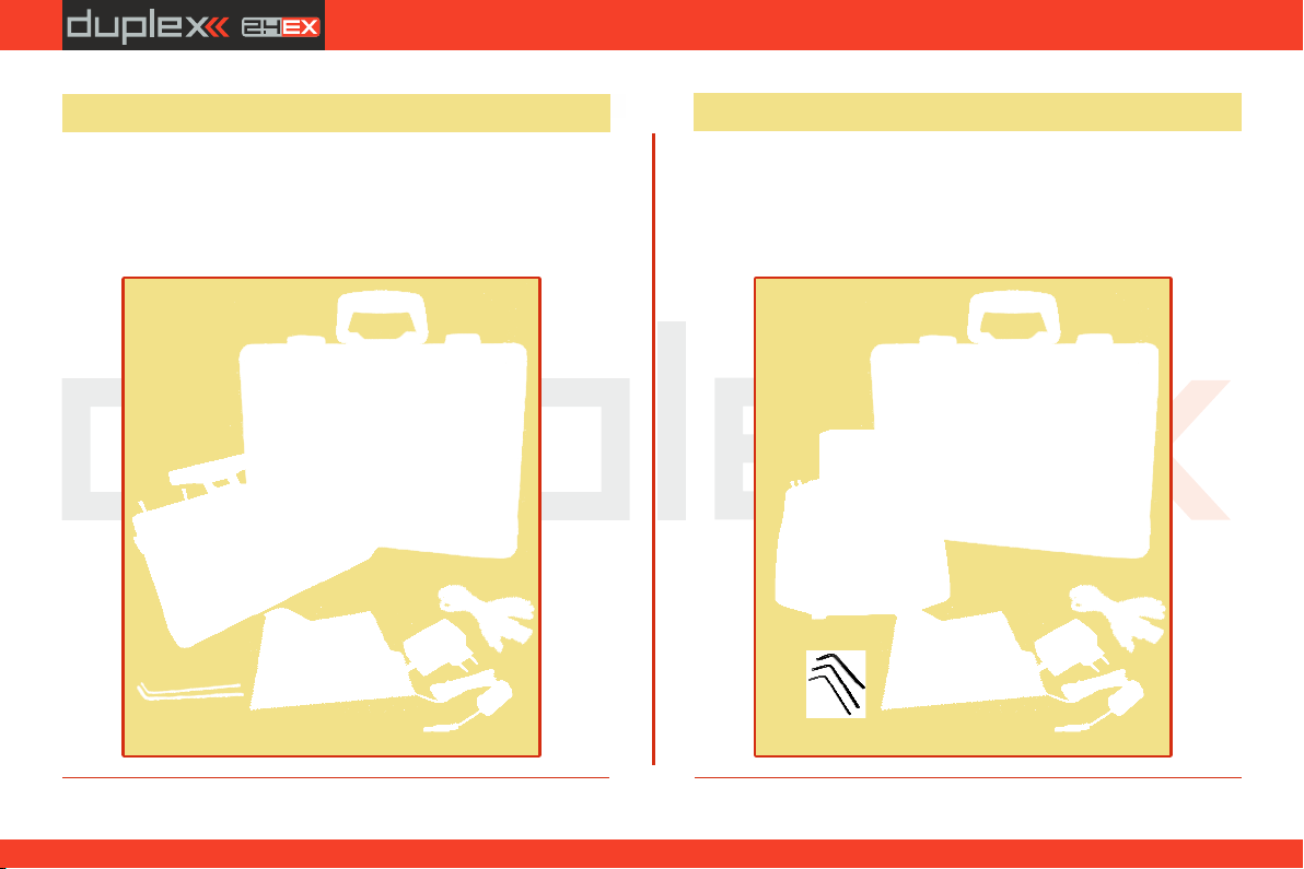
1. 2. 3. JETI DC-24 Transmitter, Wall Power Supply, JETI DC
Transmitter Aluminum Case, USB PC Cable, Installation Key Set 4. 5.
(HEX 1,5; TORX 10), Cleaning Cloth, Instruction Manuals, 6.
1
2
4
56
3
2
4
56
3
1
1.5 DC-24 Package Contents
1. 2. 3. JETI DS-24 Transmitter, Wall Power Supply, JETI DS
Transmitter Aluminum Case, USB PC Cable, Installation Key Set 4. 5.
(HEX 1,5; TORX 8; TORX10), 6. Cleaning Cloth, Instruction Manuals,
1.6 DS-24 Package Contents
10
computer radio control system EN
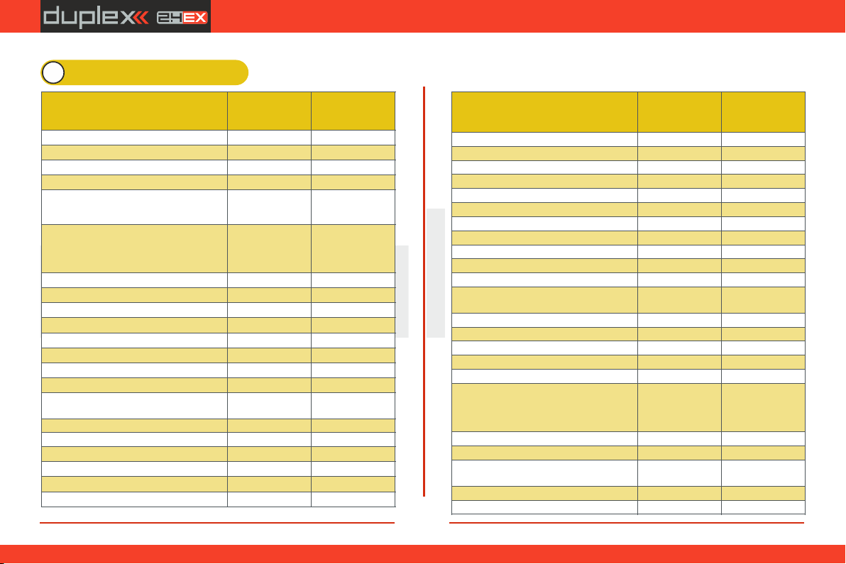
2 System Specifications
2.2.
Parameter
DS-24
DC-24
New features
free
free
Channels
24
24
Possibility for adding extra switches
l
l
Accelerometer
l
–
Secondary RF module in function:
teacher, double path
l
l
900MHz module
863 - 870 MHz
(EU)
902 - 928 Mhz
(US)
863 - 870 MHz
(EU)
902 - 928 Mhz
(US)
Flight modes
10
10
Free mixes
30
30
Graphs
l
l
Audio player
l
l
MP3 support
l
l
FM Tuner
l
l
Microphone
l
l
Vibration alarms
l
l
Color profiles, model images
l
l
Logic switches
24
24
Number of remote commands
24
24
Telemetry controls
16
16
Sequencer
10
10
Timer
10
10
Values on display
40
40
Parameter
DS-24
DC-24
Event sounds
40
40
Alarms
40
40
Telemetry sensors
64
64
Voice output
l
l
Gyro settings
3
3
Servo balancer
l
l
Function curves
l
l
Throttle limiter
l
l
Vario
l
l
Flight modes trim
l
l
Number of control directions
16 (up to 24)
16 (up to 24)
Stick material
Aluminium
MULTIMODE
Aluminium
MULTIMODE
Resolution of sticks
4096
4096
Sticks Hall sensors
l
l
Internal memory, SD cart
8 GB
8GB
RF moduls
3
3
Number of antennas
5
5
LCD backlit
3,5"
320x240px
color high
contrast
3,5"
320x240px
color high
contrast
Weight [g]
1,25
1,5
Dimensions [mm]
194x233x40
230x270x40
Transmitter Battery Pack [mAh]
Power Ion 1S2P
5200
Power Ion 1S2P
5200
Battery Charger
l
l
Aluminium case
l
l
11

computer radio control system EN
2.2.
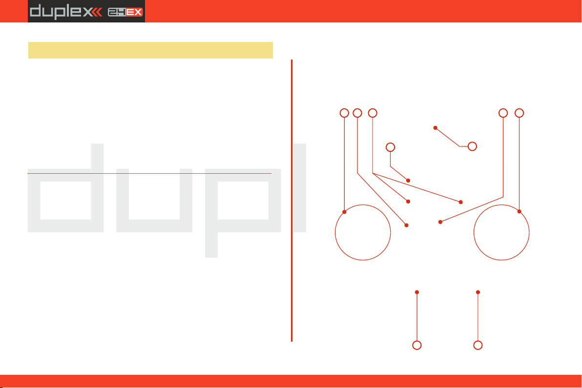
3 Description of Transmitter DC-24
1. Right Stick 1, 2 – the DC-24 Transmitter Supports Modes 1-4, see
Control Sticks -> mode change
2. Left Stick 3, 4 the DC-24 Transmitter Supports Modes 1-4, see
Control Sticks -> mode change
3. Swappable and Assignable Switches: Sa, Sb, Sc, Sd, Se, Sf, Sg, Sh, Si, Sj
4. Digital Trims for the Left Stick T3, T4
5. Digital Trims for the Right Stick T1, T2
6. Right Side Control Lever 5
7. Left Side Control Lever 6
8. Rotary Control Knob 7
9. Rotary Control Knob 8
10. LCD Display
11. Function Buttons F1 – F5
12. Transmitter On/Off Power Switch
13. 3D Control Selector
14. Menu Button
15. ESC Button
16. Antenna/ Transmitter Handle
17. Charge Jack
18. USB PC Interface
19. Earphone Jack
20. ON/OFF & Charging LED Indicators
21. Speaker
22. Harness Bracket (optional accessory) Installation Holes
23. Microphone
3.1. Control Identification
3
1
2
3
45
67
8
9
11 12 13
15 14
16
17
18
1921 2020
22 22
10
23
12
computer radio control system EN
24. Transmitter Battery Pack
25. Memory Card Micro SD 8GB
26. PPM Output Connector
27. Left Gimbal Assembly
28. Right Gimbal Assembly
29. 2.4 GHz Module
30. 900MHz Module
31. FM Antenna, PPM Input/Output
32. Battery Connector
2.2.
3.2. Assembly Identification
24 32
29 272628
DC-24
25
30
31
13
computer radio control system EN
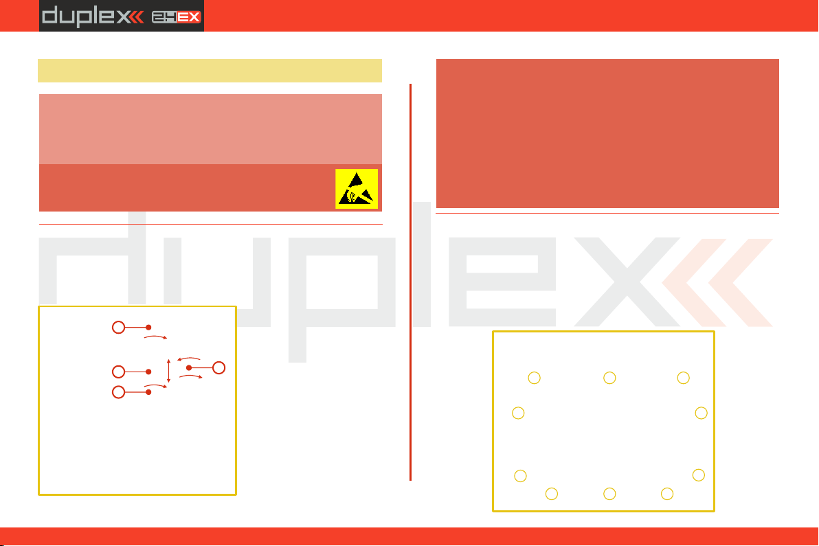
3.3 Control Stick Assembly
When handling with back cover removed always
switch off the transmitter and disconnect the
battery (unplug the connector). Also do not connect
the charging adapter or the USB cable.
Note:
Restrict your contact with the printed circuit
boards to a minimum. You can damage your
radio by electrostatic discharge!
Warning:
3.3.1 Control Stick Length Adjustment
The stick length is adjustable to suit your flying style. The stick end
separates into two parts. 1. Hold the top part of the
st ick end f ir mly and
u n s c r e w b y t u r n i n g
counter-clockwise .
2. Turn the stick end
clockwise to shorten or
c o u n te r c l o c k w i s e t o
lengthen the overall stick
length.
3. Adjust the lower part
to support the top part of
the stick end.
4. Fina lly s ecu re b y
tightening both parts to
each other.
If you have installed optional sticks with switch or button ends,
make sure that while adjusting the stick length you observe the
wires that pass through the stick shaft and through the gimbal
opening in order to prevent damaging the connecting cables.
The safest method is to remove the small set-screw from the
side of the stick housing to allow the switch or knob internals to
remain stationary while you rotatethe stick housing for height
adjustment.. (See 4.3.6)
Warning:
3.3.2 Swivel Control Stick Adjustment
In order to customize the feel of your radio you may adjust the angle
of the stick control assemblies.
1. switch off the transmitter and remove the 10 screws that secure
the radio back cover. Next, remove the radio back cover.
Be sure to disconnect the transmitter battery pack connector.
2.2.
1
2
3
4
14

computer radio control system EN
2.2.
2. Loosen both machine screws securing the control stick
assembly.
3. Adjust (rotate) to desired position.
4. Securely tighten both machine screws securing the control stick
assembly.
5. Reconnect transmitter battery pack and reinstall radio back
cover and cover screws. 3.3.4 Ratchet Tension Adjustment
Whether you prefer smooth throttle feel or ratchet throttle feel, you
can adjust the DC-24 transmitter either way you like allowing you to
fully customize your radio‘s feel. Each tension is set by a different
machine screw.
3.3.3 Control Stick Tension Adjustment
The stick gimbal tension is fully adjustable for each axis. This allows
you to fully customize your radio‘s control feel. Simply adjust each
gimbal‘s spring to your desired tension.
1. Switch off the transmitter and remove the 10 screws that secure
the radio back cover. Next, remove the radio back cover.
Be sure to disconnect the transmitter battery pack
connector.
2. Use indicated machine adjustment screws to change the
desired spring tension. By turning the screw counterclockwise,
you will loosen spring tension. As a result the moving resistance
of the control stick will decrease.
3. Reconnect transmitter battery pack and reinstall radio back
cover and cover screws.
1. Switch off the transmitter and remove the 10 screws that secure
the radio back cover. Next, remove the radio back cover.
Be sure to disconnect the transmitter battery pack
connector.
2. For ratchet tension adjustment use the machine screw “ ”. A
Turn slowly (counter-clockwise) until you achieve the desired
ratchet tension. For smooth tension adjustment, use the achine
screw “ ”. Turn slowly (clockwise) until you achieve the B
By turning the screw clockwise, you will tighten spring tension. As a
result the moving resistance of the control stick will increase.
DC-24DC-24DC-24
3
4
4
2
2
2
2
DC-24DC-24DC-24
15
computer radio control system EN
2.2.
desired smooth tension.
3. Reconnect transmitter battery pack and reinstall radio back
cover and cover screws.
3.3.5 Throttle stick travel adjustment
The throttle stick travel is adjustable to suit your flying style.
1. Switch off the transmitter and remove the 8 screws that secure the
radio back cover. Next, remove the radio back cover. Be sure to
disconnect the transmitter battery pack connector.
2. Use indicated machine adjustment screws to limit the throttle
stick travel. By turning the screw
clockwise, you will shorten the
throttle stick travel.
3. Reconnect transmitter battery
pack and reinstall radio back
cover and cover screws.
After making a limit the throttle
stick travel you must re-calibrate
DC-24DC-24DC-24
AB
2
DC-24DC-24DC-24
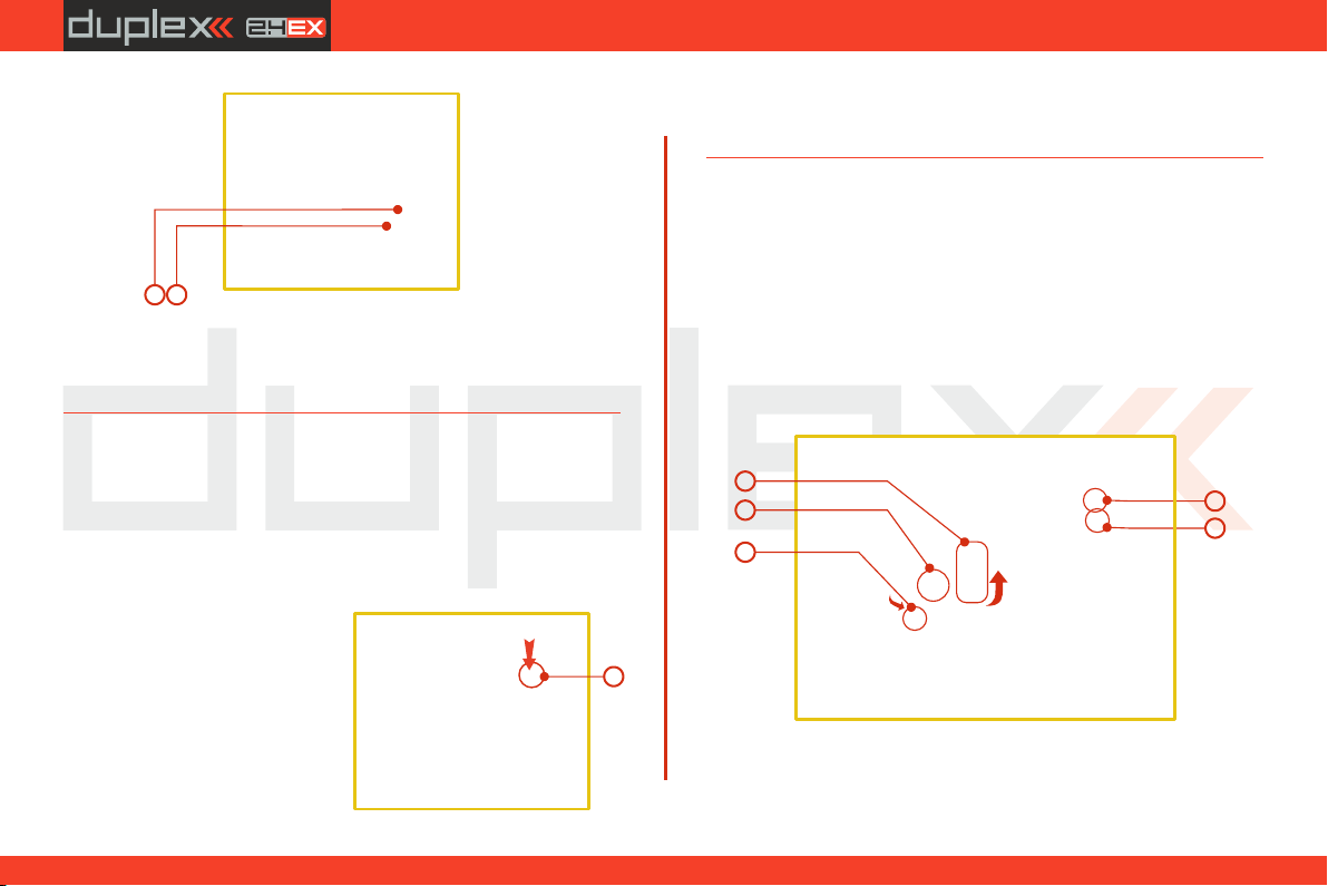
3.3.6 Changing the transmitter mode
The transmitter is equiped with universal multimode gimbals. Both
gimbals are identical and can be adjusted mechanically for modes 1-
5. After mechanical adjustment it is necessary to set a specific
transmitter mode in the menu System – Configuration – Stick mode
1-4.
To change the quad sticks settings, unscrew the back cover of the
transmitter and disconnect the battery connector.
A. Setting the quad stick into the mode without locking the
middle position - gas
E
D
5
5
1
A
C
B
2
3
the transmitter stick in the software menu, see section 9.6.3
–Calibration of Proportional Controls.
1. A. Loosen the screw
2. C. Lift the lever B so as it is possible to arrest the lock
3. C Turn the lock 90° in the direction of the arrow and arrest the
lever in the upper position. B
16

computer radio control system EN
3.3.7 Transmitter Gimbals with Switch or Button
Installation
If you want to operate the DC-24 transmitter using the optional stick
end switch or button functions, you must purchase one or more of
these separately:
• Stick with 2-position switch
• Stick with 3-position switch
• Stick with push-button
• Stick with potenciometer
For installation of the optional gimbal stick ends with
switches/buttons we recommend that you send your
transmitter to one of the factory authorized service
centers or to your authorized dealer.
Advice:
2.2.
1. Switch off the transmitter and remove the 10 screws that secure
the radio back cover. Next, remove the radio back cover.
Be sure to disconnect the transmitter battery pack
connector.
4. A. Tighten the screw
5. D E Tightening the the screws and sets the desired arresting with
steps and smooth brake.
B. Setting the multi-mode gimbal into the mode with locking
the middle position - elevator
B
1A
C
2
3E
D
5
1. A. Loosen the screw
2. B. Slightly lift the lever
3. C B Turn the lock in the direction of the arrow and arrest the lever
in the upper position.
4. C Move the lever in the direction of the arrow to release the lever
B.
5. A. Tighten the screw
6. E D Loosen the screws and in a position so that the tension is
removed from the stick.
DC-24DC-24DC-24
2
3
4
4
XXX
YYY
SSS
17

computer radio control system EN
5. Carefully remove both control stick assemblies. Gently pull in
your direction (toward the transmitter back side). This upgrade
will be done outside of the transmitter case.
6. Unscrew the upper part of the stick assembly (anticlockwise).
7. Insert the connecting wires through the hollow opening of the
transmitter stick.
8. Adjust length of the stick to suit your flying style.
2.2.
2. Disconnect the control stick assembly wires from the Tx board.
(3 wires )X, Y, S
3. Remove the stick assembly connecting wires from their holders.
4. Remove both machine installation screws for each of the
control stick assemblies.
After installation of the optional stick ends with switch or
button make sure that while adjusting the stick length you
observe the wires that pass through the stick shaft and
through the gimbal opening in order to prevent damaging
the connecting cables. The safest method is to remove the
small set-screw from the side of the stick housing to allow
the switch or knob internals to remain stationary while you
rotate the stick housing for height adjustment.
9. Pass the switch wires through the same gimbal opening as the
hall sensor cable (through the center of the gimbal assembly).
10. Next insert wire ends through the opening of the printed circuit
board and solder them to the matching soldering points in such
a way that the same color wires lay on the top of each other.
11. Carefully move transmitter sticks to their full outside positions in
order to make sure that you have sufficient wire length and, if
needed, adjust accordingly. The connecting cables for all
moving parts of the unit should have sufficient length in order
not to be exposed to any mechanical damage and any bending
stresses.
Note:
8
9
10
11
7
6
DC-24DC-24DC-24
14 XXXYYY
SSS15
13
13
18

computer radio control system EN
3.4 Swappable and Assignable Switches
One of the most important features of a JETI transmitter is the switch
function assignment flexibility. The DC-24 transmitter automatically
detects the type of switch and assigns the selected function. There
are many switches available to suit different needs.See your Jeti
retailer for switch availability.
You may either swap the existing switches around or take advantage
of the optional accessories and create your own custom
configuration.
Factory Switch Configurations for the DC-24Transmitter
Sa - 2- position spring-loaded long switch
Sb - 3- position short switch
Sc - 2- position short switch
Sd - 2- position long switch
Se - 3- position short switch
Sf - 3- position short switch
Sg - 3- position long switch
Sh - 2- position short switch
Si - 2- position short switch
Sj - 3- position long switch
2.2.
After the switch has been installed into the stick assembly you have
to re-configure and enable it in the transmitter software before it will
function properly. This can be done in the transmitter menu "Main
menu->Advanced setup->Sticks/ switches setup“, (see Installation
and Configuration of Gimbals Switches 9.3.2)
12. Install stick unit assembly back to correct position.
13. Install and secure the machine screws for the control stick
assembly.
14. Connect control stick assembly wires to the Tx board connector
(3 wires ). Pay close attention to the wire lengths. Connect X, Y, S
the longest wire as the first one from the outside of the
transmitter (3 connectors ).X, Y, S
15. Secure the stick assembly wires into their holders.
16. Reconnect transmitter battery pack and reinstall radio back
cover and cover screws.
19
This manual suits for next models
2
Table of contents
Other Jeti Transmitter manuals


