Jeti Duplex DC16 User manual

3998 FAU Blvd. Suite 310 Boca Raton, FL 33431 Tel: 561-961-5585 Fax: 561-961-5587
Certification Exhibit
FCC ID: ONTJETIDC16US
IC: 10491A-JETIDC16US
FCC Rule Part: 15.247
IC Radio Standards Specification: RSS-210
ACS Project: 12-2095
Manufacturer: Esprit Model
Model: JETIDC16US
User Manual
computer radio control system EN
The new DC16 transmitter was developed and produced with the
cooperation of professional and world champion pilots. This
transmitter was created with the goals of maximum utility, simple
handling, maximum durability and the ultimate reliability of its
mechanical parts. The metal case, with its chemically resistant
outside surface treatment, provides maximum protection for the
interior components. The straightforward case shape makes
servicing easy. The metal, quad ball bearing equipped, stick gimbals
with their magnetic Hall sensors are another revolutionary design
concept used to make the DC16 one of the world’s most advanced
R/C systems.
Purposefully placed at the top of the transmitter, the 3.8“ backlit, LCD
display with its wide viewing angle offers nearly perfect visibility in
just about any lighting condition. Thanks to its high resolution
display and use of a relatively large number of graphic images it was
possible to create a simple and intuitive setup procedure for
displaying telemetric data.
The DUPLEX EX family of products have been equipped with an
improved telemetric data transfer system which can be viewed on
the LCD transmitter display or saved for later analysis on a PC. The
transmitter allows the setup of audible notifications (optionally
created by the user), which can be related to actual telemetric values
or to sound alarms or signals which have been assigned to
conditions of various control elements.
Duplex 2,4GHz – the DC-16 transmitter features the Duplex 2.4GHz,
frequency hopping, digital, data stream system originally developed
by Jeti Model in the Czech Republic. This system has been reliably
used for many years.
Built-in Telemetry – from the start, the DC-16 transmitter was
designed and built with many attractive features and includes the
full integration of all Duplex telemetry sensors.
Design of the DC-16 Transmitter – this design emphasizes user
comfort, state-of-the-art appearance, and uses premium quality
materials.
Precise Metal Gimbals – transmitter gimbals equipped with Hall
sensors and ball bearings for precision movement with an almost
unlimited lifespan.
LCD Display – oversized 3.8“ backlit LCD display with 320x240
resolution which is highly visable under any light conditions.
Li-Ion Battery – provides a proven and reliable energy source with a
high capacity (3200mAh) and a long service life.
Easy Charging – simply connect the wall power supply to the
transmitter. The DC-16 may also be charged used through its USB to
PC interface.The charging progress is shown on the DC-16 display.
Integrated Antenna – the antenna covers & tx handle are an integral
part of the transmitter case which protects the RF antennas from
mechanical damage.
1 Introduction
1.1.
1.1 Features
computer radio control system EN
Large Memory – 4GB memory space for storing models, sounds, and
telemetry data.
USB Connector – convenient connection to your PC. Fast firmware &
sound upgrades, telemetry data downloads.
Fast Navigation – 3D wheel-style interface combined with function
keys allow for speedy navigation within the DC-16 menu.
Digital Trims – fully programmable trims and a revolutionary
automatic trimming function.
Swappable and Assignable Switches – all of the switches on the DC-
16 transmitter (2- or 3-position) can be easily moved and assigned to
create a custom configuration that works best for your application.
Programming – the logical and intuitive transmitter firmware is
designed to be simple to use. Just follow the step-by-step screens.
The creation of a new model can be accomplished with just a few
easy steps.
Sounds/Alarms – the DC-16 transmitter is equipped with audible
alarms and also allows the use of user-recordable alarms and sounds
to keep you fully informed while also keeping distractions to a
minimum.
To make navigation faster, the DC-16 transmitter Instruction Manual
has been divided into 5 basic groups:
1 . Introduction and product support.
2. Basic description and mechanical adjustments.
3. First time switch-on. Basic helicopter and airplane set-up.
4. Advanced programming. Detailed descriptions.
5. PC upgrade/upload, safety information, and special mixes.
Important parts of the instructions are separated from the text and
highlighted according their importance.
Advice Note Warning
Advanced modelers may want to begin with group 3 where you will
get all of the basic information for model set-up. This is the quickest
way to understand the basic ideas of the DC-16 transmitter
programming and with this basic information you can begin to
create your own model. More advanced programming functions are
found in group 4. This is where you can find detailed descriptions of
all of the DC-16 functions. The last section provides detailed
description of firmware upgrades, downloads, and special mixes.
1.1.
1.2 Table of Contents

computer radio control system EN
If you feel uncertain about how to set up particular transmitter
functions, do not hesitate to take advantage of our technical
support:
1. Web Site
Either the Jeti Model (manufacturer) or your local distributor’s web
sites offer a wide range of support for the DC-16 transmitter. You will
find advice, tips or frequently asked questions (FAQ) which, in most
cases, contain the answers to your questions.
2. Distributor, Manufacturer
You may also find support at your local hobby shop, distributor, or
directly with the manufacturer Jeti Model s.r.o.
3. Service and Warranty Coverage
Jeti Model CZ exclusively warranties that the products purchased will be
free from defects in materials and workmanship for a period of 24 months
from the date of purchase by the customer. This warranty covers only
those products purchased from an authorized Jeti Model CZ distributor or
dealer. Third party transactions are not covered by this warranty. Proof of
purchase is required for warranty claims. Repair or replacement decisions
are at the sole discretion of Jeti Model CZ or an authorized service
provider. This warranty does not cover cosmetic damage or damage due
to an accident, misuse, abuse, negligence, commercial or research use, or
modification of or to any part of the product. This warranty does not cover
damage due to improper installation, operation, maintenance, or
attempted repair by anyone other than Jeti Model CZ or an authorized
service provider.
Jeti Model CZ reserves the right to change or modify this warranty
without notice and disclaims all other warranties, expressed or implied.
1. 2. 3. Jeti DC-16 Transmitter, Wall Power Supply, Jeti DC-16
Transmitter Aluminum Case, Transmitter Work Pad, Jeti Duplex 4. 5.
R9EX 2.4GHz Receiver + Bind Plug, USB PC Cable, Installation 6. 7.
Hex Key Set (1,5mm; 2mm), Cleaning Pad, Instruction Manuals 8.
1. 2.
1
3
2
6
5
7
48
1.3 Technical Support 2 Included, Accessories
2.1 Included:
computer radio control system EN
• Transmitter Neck Strap Bracket
• Transmitter Tray
• 4-Point Adjustable Harness
• Neck Strap
• Additional switches for DC-16 Transmitter
• Special Switch Removal Wrench
• Tx Sticks with 2- or 3-position Switches/Push Buttons
• Replacement Li-Ion 3200mAh Battery
• Replacement Aluminum Case
• Wireless Trainer Module
• Wide Assortment of 4 to 18-channel Duplex Receivers
• Wide Assortment of Jeti Telemetry Sensors
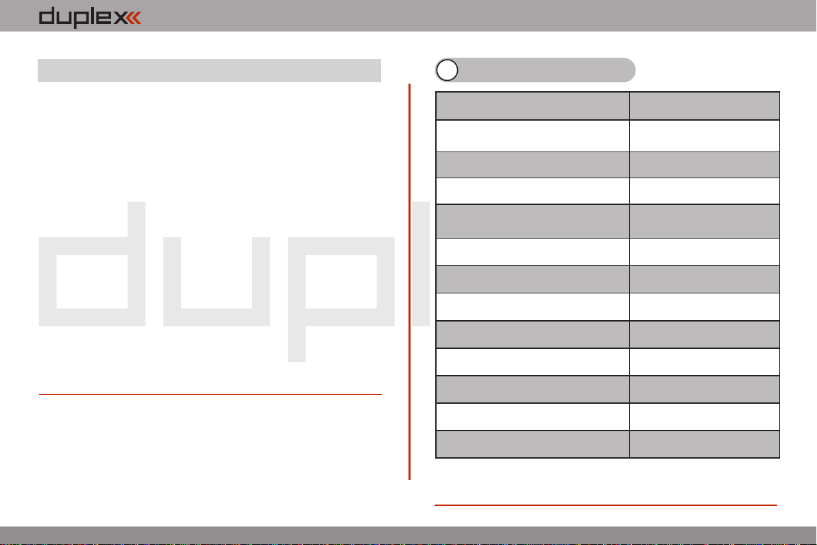
3 System Specifications
Frequency
2.4GHz
Dimensions
WxLxH (with Antenna)
180x270x40,
(230x270x40)
Weight
1.5Kg
Number of Channels
16
Number of control directions
using all Sticks/Switches/Knobs
Up to20
Resolution
4096 steps
Battery
Li-on 3200mAh 3.6V
Operating Time
Up to 11 hours
Internal Memory
microSD 4GB
Telemetry
Yes
PC Connection
USB mini
Graphic Display
3,8" - 320x240px
Operational Temperature
-10 up 60 °C
2.2.
2.2. Optional Accessories (Not Included)
computer radio control system EN
2.2.
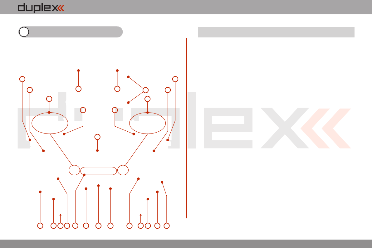
4 Description of Transmitter
1. Right Stick 1, 2 – the DC-16 Transmitter Supports Modes 1-4, see Control
Sticks -> mode change
2. Left Stick 3, 4 the DC-16 Transmitter Supports Modes 1-4, see Control
Sticks -> mode change
3. Swappable and Assignable Switches: Sa, Sb, Sc, Sd, Se, Sf, Sg, Sh, Si, Sj
4. Digital Trims for the Left Stick T3, T4
5. Digital Trims for the Right Stick T1, T2
6. Right Side Control Lever 5
7. Left Side Control Lever 6
8. Rotary Control Knob 7
9. Rotary Control Knob 8
10. LCD Display
11. Function Buttons F1 – F5
12. Transmitter On/Off Power Switch
13. 3D Control Selector
14. Menu Button
15. ESC Button
16. Antenna/ Transmitter Handle
17. Charge Jack
18. USB PC Interface
19. Earphone Jack
20. ON/OFF & Charging LED Indicators
21. Speaker
22. Transmitter Neck Strap Bracket Installation Holes
3
1
2
3
45
67
89
10
11 12 13
15 14
16
17
18
1921 2020
22 22
4.1. Control Identification

computer radio control system EN
23. Battery Connector
24. Transmitter Battery Pack
25. PPM Output Connector
26. Left Gimbal Assembly
27. Right Gimbal Assembly
2.2.
24 23
25 2627
4.2. Assembly Identification
computer radio control system EN
4.3 Control Stick Assembly
When handling with back cover removed always
switch-off the transmitter and disconnect the
battery (unplug the connector). Also do not connect
the charging adapter or the USB cable.
Note:
Restrict your contact with the printed circuit
boards to a minimum. You can damage your
radio by electrostatic discharge!
Warning:
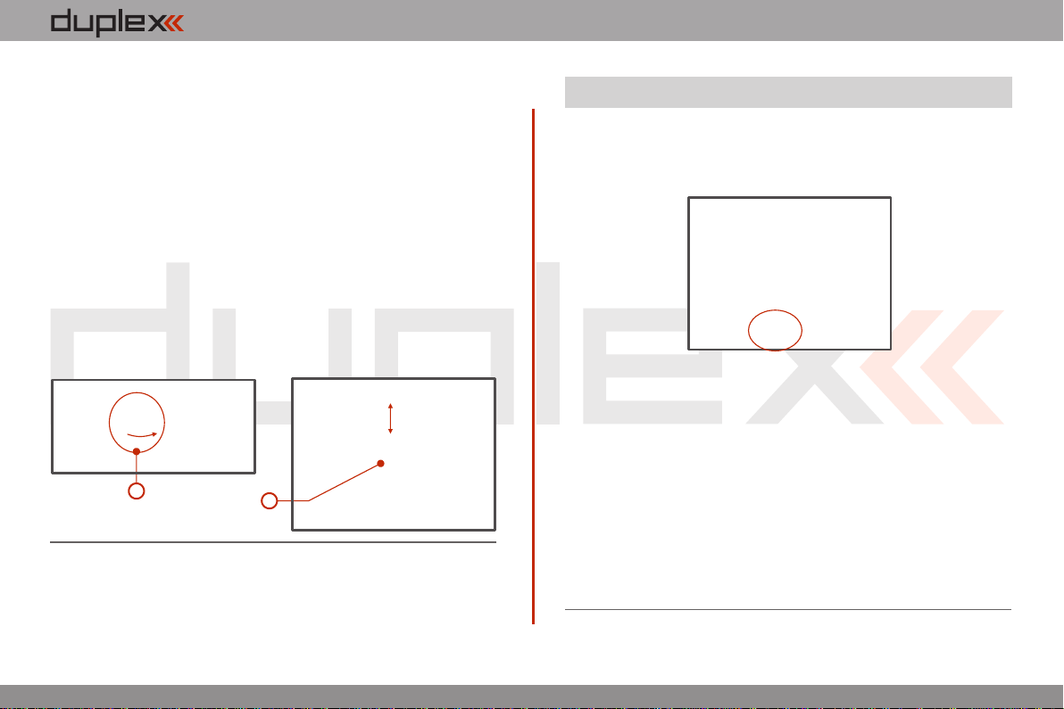
4.3.1. Control Stick Length Adjustment
The stick length is adjustable to suit your flying style. The stick end
separates into two parts. 1. Hold the top part of the
stick end firmly and
unscrew (turn it
anticlockwise).
2. Turn the stick end
clockwise to shorten or
counterclockwise to
lengthen the overall stick
length.
3. Adjust the lower part
to support the top part of
the stick end.
4. Finally secure by
tightening both parts to
each other.
1
2
3
4
If you have installed optional sticks with switch or
button ends; make sure that while adjusting the
stick length you observe the wires that pass through
the stick shaft and through the gimbal opening in
order to prevent damaging the connecting cables.
The safest method is to de-solder the stick end
switch control wires and remove them from the
gimbal opening during adjustment. (See 4.3.6)
Warning:
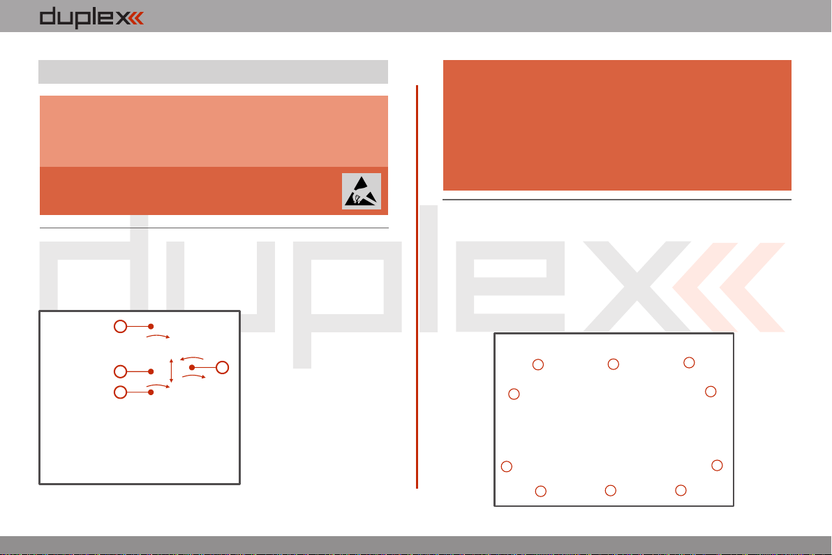
4.3.2. Swivel Control Stick Adjustment
In order to customize the feel of your radio you may adjust the angle
of the stick control assemblies.
1. Switch-off the transmitter and remove the 10 screws that
secure the radio back cover. Next, remove the radio back cover.
Be sure to disconnect the transmitter battery pack connector.
2.2.
computer radio control system EN
2.2.
2. Loosen both machine screws securing the control stick
assembly.
3. Adjust (rotate) to desired position.
4. Securely tighten both machine screws securing the control stick
assembly.
5. Reconnect transmitter battery pack and reinstall radio back
cover and cover screws.
3
4
2
4
2
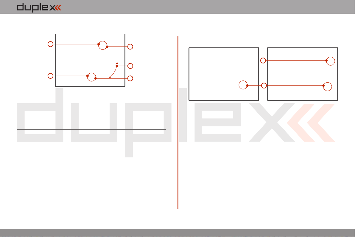
4.3.4. Ratchet Tension Adjustment
Do you prefer smooth throttle feel or ratchet throttle feel? You can
adjust the DC-16 transmitter either way you like allowing you to fully
customize your radio‘s handling. Each tension is set by a different
machine screw.
4.3.3. Control Stick Tension Adjustment
The stick gimbal tension is fully adjustable for each axis. This allows
you to fully customize your radio‘s control feel. Simply adjust each
gimbal‘s spring to your desired tension.
1. Switch-off the transmitter and remove the 10 screws that secure
the radio back cover. Next, remove the radio back cover.
Be sure to disconnect the transmitter battery pack
connector.
2. Use indicated machine adjustment screws to change the
desired spring tension.
By turning the screw anticlockwise, you will loosen spring
tension. As a result the moving resistance of the control stick will
3. Reconnect transmitter battery pack and reinstall radio back
cover and cover screws.
1. Switch-off the transmitter and remove the 10 screws that secure
the radio back cover. Next, remove the radio back cover.
Be sure to disconnect the transmitter battery pack
connector.
2
2
2. For ratchet tension adjustment use the machine screw “A”.
Turn slowly (anticlockwise) until you achieve the desired
ratchet tension. For smooth tension adjustment, use the
achine screw “B”. Turn slowly (clockwise) until you achieve
decrease. By turning the screw clockwise, you will tighten
spring tension. As a result the moving resistance of the control
stick will increase.

computer radio control system EN
2.2.
AB
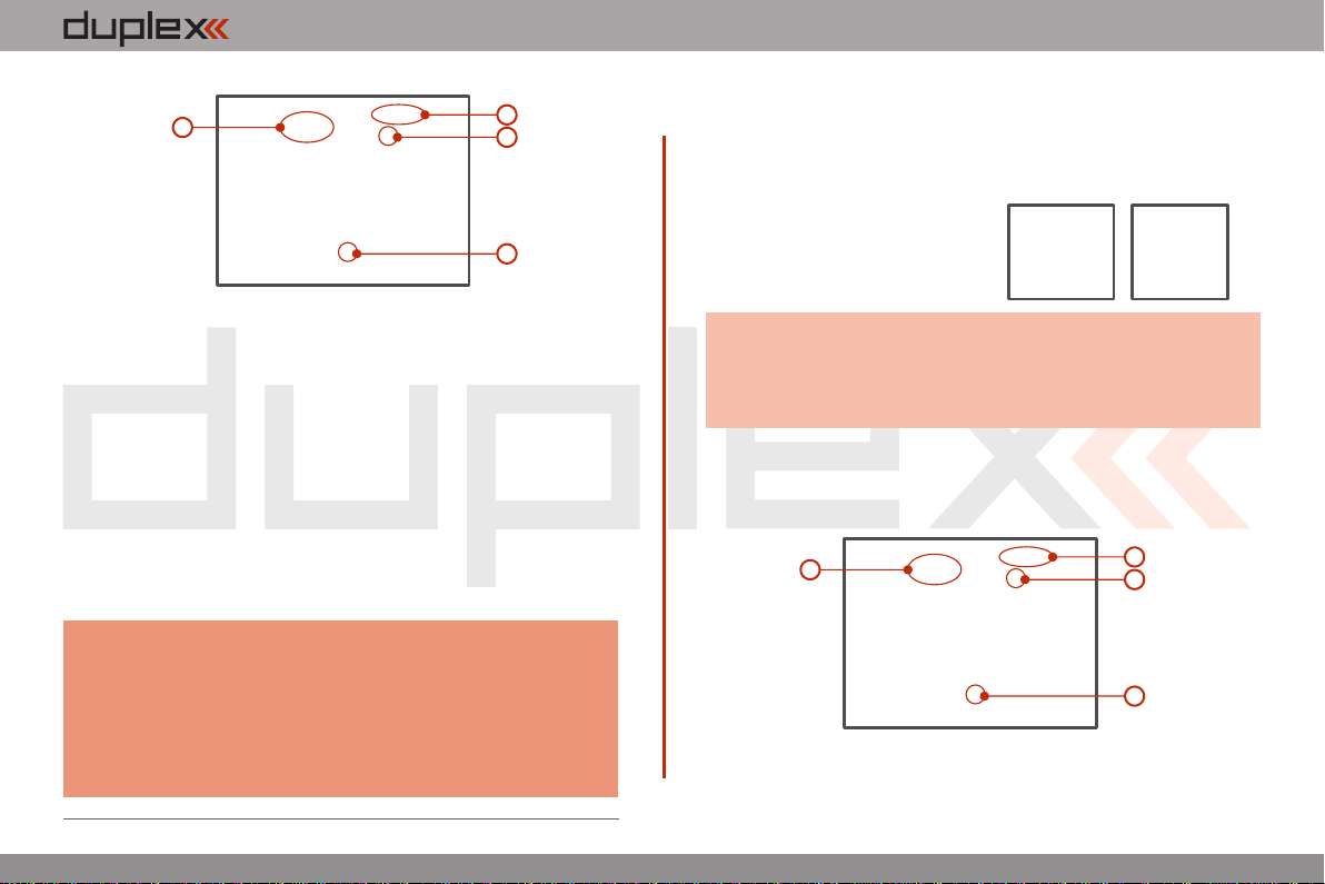
4.3.5. Transmitter Mode Switch
The DC-16 transmitter allows you to switch between Mode 1, 2, 3
and 4 stick configurations with just few simple steps. In order to do
some of these, the stick control assemblies will need to be swapped.
1. Switch-off the transmitter and remove the 10 screws that secure
the radio back cover. Next, remove the radio back cover.
Be sure to disconnect the transmitter battery pack
connector.
2. Disconnect the control stick assembly wires from the Tx board.
(3 wires X, Y, S)
3. Remove the stick assembly connecting wires from their holders.
It may be necessary to remove the screws securing the RF circuit
board to release the wire group.
2
34
4
4. Remove both machine installation screws for each of the
control stick assemblies.
5. Carefully remove both control stick assemblies. Gently pull in
5
6
XYS
the desired smooth tension.
3. Reconnect transmitter battery pack and reinstall radio back
cover and cover screws.
computer radio control system EN
8
97
7
your direction (toward the transmitter back side).
6. Swap both stick unit assemblies and install them back into
correct positions.
7. Reinstall and secure the machine screws for each of the control
stick assemblies.
8. Connect control stick assembly wires to the Tx board connector
(3 wires X, Y, S ). Pay close attention to the wire lengths. Connect
the longest wire as the first one from the outside of the
transmitter (3 connectors X, Y, S).
9. Secure the stick assembly wires into their holders.
10. Reconnect transmitter battery pack and reinstall radio back
cover and cover screws.
After making a mode switch you must re-calibrate the
transmitter stick assemblies and set-up the correct
mode in the software menu, see section 9.6.1 –
Configuration. The switch between Modes 1 to 3 or
Modes 2 to 4 are done with the software only (NO
manual stick change is necessary).
Note:
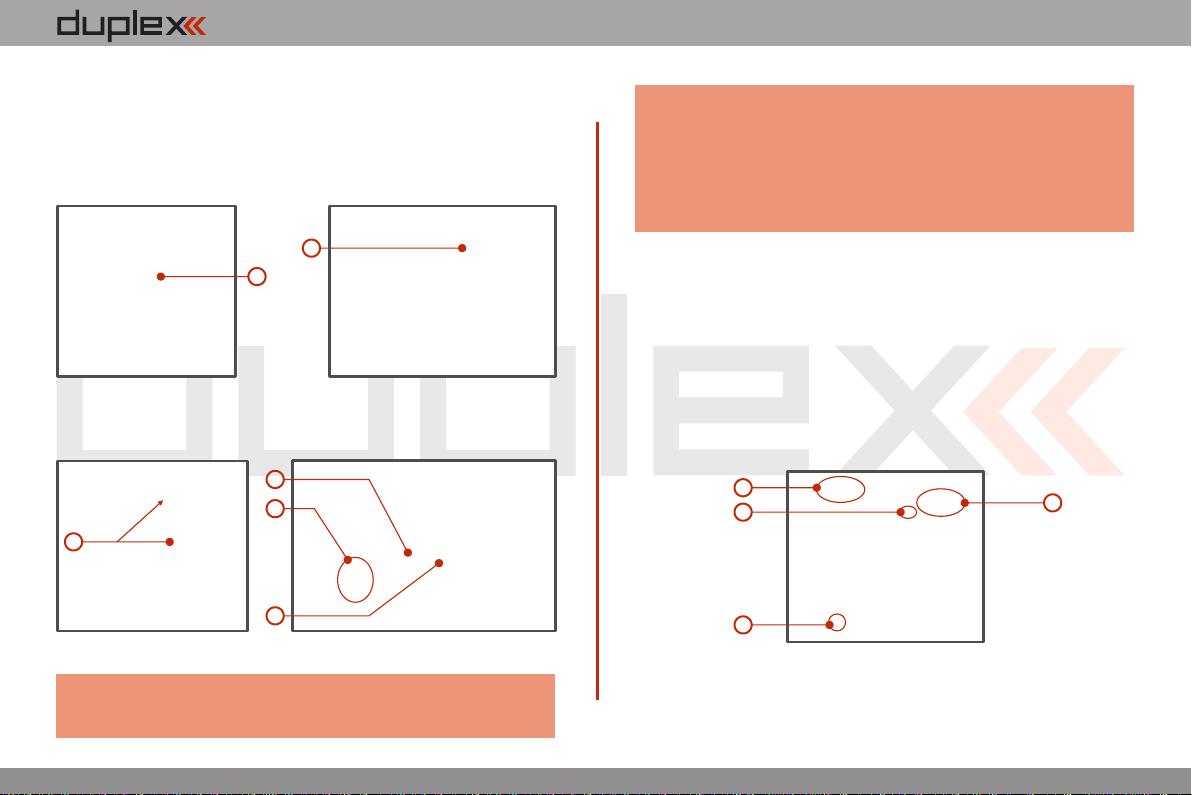
4.3.6. Transmitter Gimbals with Switch or Button
Installation
If you want to operate the DC-16 transmitter using the optional stick
end switch or button functions, you must purchase one or more of
these separately:
• Stick with 2-position switch
• Stick with 3-position switch
• Stick with push-button
For installation of the optional gimbal stick ends with
switches/buttons we recommend that you send your
transmitter to one of the factory authorized service
centers or to your authorized dealer.
Advice:
1. Switch-off the transmitter and remove the 10 screws that secure
the radio back cover. Next, remove the radio back cover.
Be sure to disconnect the transmitter battery pack
connector.
2. Disconnect the control stick assembly wires from the Tx board.
(3 wires X, Y, S)
3. Remove the stick assembly connecting wires from their holders.
2
34
4
XYS
XYS
2.2.
computer radio control system EN
5. Carefully remove both control stick assemblies. Gently pull in
your direction (toward the transmitter back side). This upgrade
will be done outside of the transmitter case.
6. Unscrew the upper part of the stick assembly (anticlockwise).
7. Insert the connecting wires through the hollow opening of the
transmitter stick.
6
7
8. Adjust length of the stick to suit your flying style. (See 4.3)
After installation of the optional stick ends with switch or
button; make sure that while adjusting the stick length
Note:
8
9
10
11
2.2.
4. Remove both machine installation screws for each of the
control stick assemblies. you observe the wires that pass through the stick shaft
and through the gimbal opening in order to prevent
damaging the connecting cables. The safest method is
to de-solder the stick end switch control wires and
remove them from the gimbal opening during
adjustment.
9. Pass the switch wires through the same gimbal opening as the
hall sensor cable (through the center of the gimbal assembly).
10. Next insert wire ends through the opening of the printed circuit
board and solder them to the matching soldering points in such
a way that the same color wires lay on the top of each other.
11. Carefully move transmitter sticks to their full outside positions
in order to make sure that you have sufficient wire length and, if
needed, adjust accordingly. The connecting cables for all
moving parts of the unit should have sufficient length in order
not to be exposed to any mechanical damage and any bending
stresses.
12. Install stick unit assembly back to correct position.
13. Install and secure the machine screws for the control stick
assembly.
14 XY
S15
13
13

computer radio control system EN
4.4 Swappable and Assignable Switches.
One of the most important features of a Jeti transmitter is the switch
function assignment flexibility. The DC-16 transmitter automatically
detects the type of switch and assigns the selected function. The
following switch types are available:
• 2-position short or long switch
• 2-position spring-loaded long switch
• 3-position short or long switch
You may either swap the existing switches around or take advantage
of the optional accessories and create your own custom
configuration.
Factory Switch Configurations for the DC-16 Transmitter
Sa - 2- position spring-loaded long switch
Sb - 3- position short switch
Sc - 2- position short switch
Sd - 2- position long switch
Se - 3- position short switch
Sf - 3- position short switch
Sg - 3- position long switch
Sh - 2- position short switch
Si - 2- position short switch
Sj - 3- position long switch
2.2.
Installation and Configuration of Gimbals Switches
After the switch has been installed into the stick assembly you have
to re-configure and enable it in the transmitter software before it will
function properly. This can be done in the transmitter menu „Main
menu->Advanced setup->Sticks/ switches setup“, see section
9.3.2.
14. Connect control stick assembly wires to the Tx board connector
(3 wires X, Y, S ). Pay close attention to the wire lengths. Connect
the longest wire as the first one from the outside of the
transmitter (3 connectors X, Y, S).
15. Secure the stick assembly wires into their holders.
16. Reconnect transmitter battery pack and reinstall radio back
cover and cover screws.
computer radio control system EN
2.2.
3
Switch Exchange:
1. Switch-off the transmitter and remove the 10 screws that secure
the radio back cover. Next, remove the radio back cover.
Be sure to disconnect the transmitter battery pack
connector.
2. With the specialized wrench (not included) carefully loosen and
remove the switch installation nut.
3. Carefully hold the switch by its printed circuit board assembly
and slowly pull it out. Use this method to also remove and
exchange all of the other switches. After re-assembling and
turning on your transmitter the software will sound a warning
reminding you that you have executed a change. Always re-
inspect all assigned functions of the switches before
attempting to fly.
2
4.5 Digital Trims.
Transmitter gimbals are used for controlling the basic flight
functions like throttle, roll(aileron), pitch(elevator), and yaw(rudder).
Immediately under the transmitter gimbal sticks you can see four
push-buttons which are the programmable, digital trim buttons.
The digital trims are used for fine trimming of the flying model. When
the transmitter is turned off, the trim values are stored in memory
and are recalled when the system is turned back on.
Every model has its own trim setup. Also all flight modes may be
configured to use different trim configurations. By pressing one of
the buttons, the screen will automatically change to display the
graphic position of that trim. The transmitter trims feature an
acoustic step and centre beep alarm.
In the „Digital trim“ menu it‘s possible to enable a special
function used as automatic trimming. Digital trim steps and trim
range setting is explained in „Main menu->Fine tuning/flight
modes->Digital trim“

computer radio control system EN
4.6.2. Battery Replacement
Should you decide to replace the transmitter battery, please follow
these steps:
1. Switch-off the transmitter and remove the 10 screws that
secure the radio back cover. Next, remove the radio back cover.
2. Disconnect the transmitter battery connector.
3. Loosen the battery fastening strap and remove the battery.
32
DC-16 transmitters should only be operated only
with original or manufacturer approved battery
packs. The use of other battery packs will void the
warranty.
Warning:
If the transmitter battery has been disconnected for
longer than 1 minute; the time, and date will be deleted.
Note:
2.2.
4.6 Transmitter Battery Pack.
The DC-16 transmitter is powered by a Li-Ion type battery pack and
comes equipped with its own built-in advanced battery
management and charging circuit. In switched-on position, the
transmitter LCD display shows the status and condition of the
battery pack. The Li-Ion battery is factory installed.
4.6.1. Charging
The DC-16 transmitter can be charged with the included wall power
supply or through the built-in USB port.
For fast charging use the included wall power supply. Charging time
is around 3 hours. During the charging process the transmitter can
be in switched-on or off position. The charging status is clearly
shown by lit red and green LEDs. If the transmitter is switched on
during the charging process you can see the charging progress
directly on the LCD display.
Transmitter Charging:
1. Plug-in the included power supply to a wall outlet.
2. Plug the main charging connector into the transmitter. If the
green LED goes out, the transmitter is not fully charged. The
red LED indicates the battery charging status.
• Discharged battery – red LED is slow blinking, the green LED
is OFF
Close to full charge – red LED is permanently ON, the green •
LED is OFF
Fully charged battery – the red and green LEDs are ON•
computer radio control system EN
4.8. Handling
The DC-16 transmitter can be comfortably carried by holding it for
the antenna cover/handle as shown on the picture.
Before each flying session, and especially with a new
model, it’s important to perform a range check.
If you are operating a model with a DC-16
transmitter do not shield and avoid contact of the
transmitter antenna with your body.
Warning:
2.2.
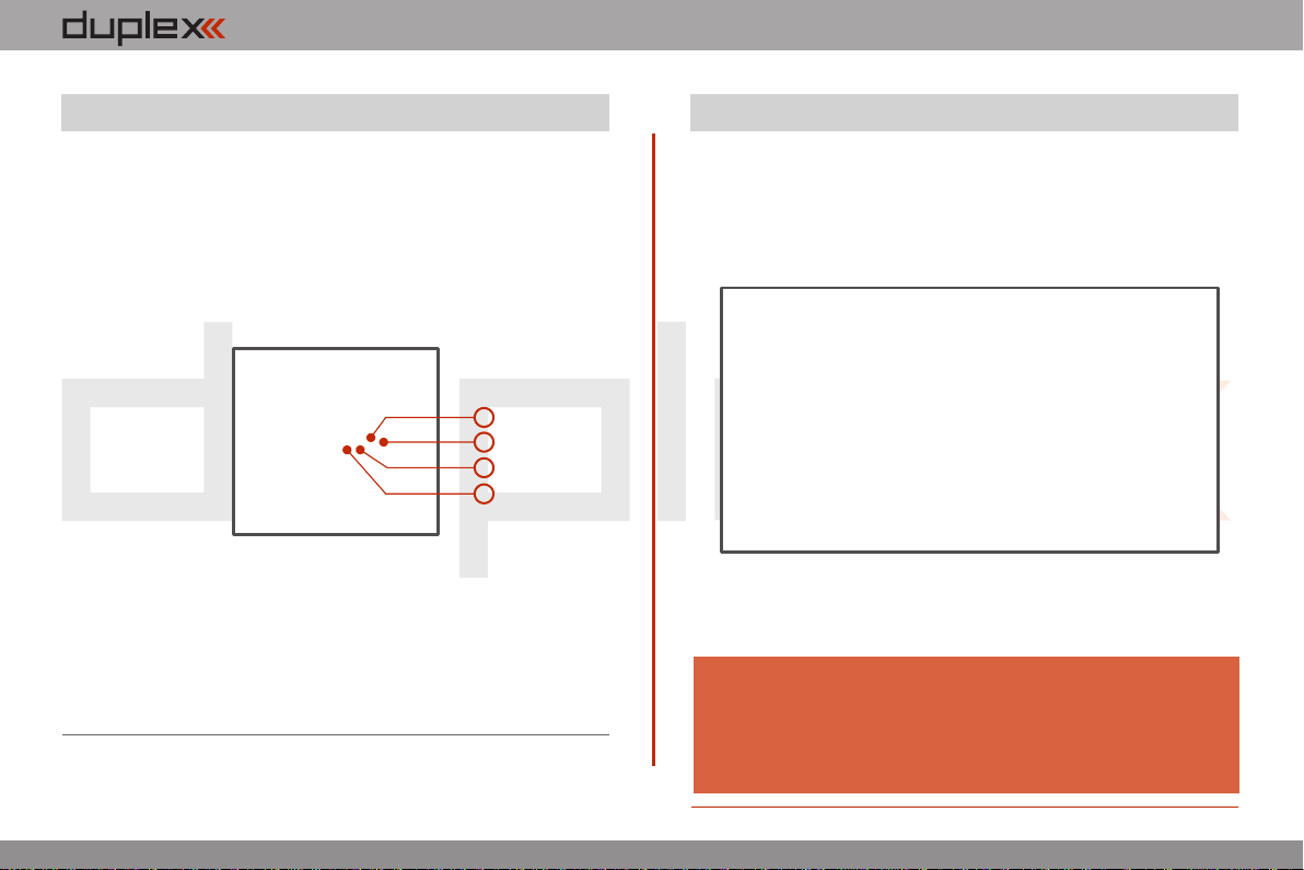
4.7. PPM Output Connector
The PPM output is accessible via connector labeled „B“. This
connector features the non-stabilized battery voltage output in the
range of 3,2V - 4,2V (max. 1A) which can be used as power supply for
the connected HF module as well as for the PPM signal output. The
transmitter output functions are in the form of a standard PPM
signal.
3
1. Reserve pin (do not connect)
2. Positive pin
3. Negative pin
4. PPM signal output (3V logics)
4
2
1

computer radio control system EN
5 RF Transmitter Modules
In order to achieve the highest transmission quality and reliability of
the DC-16 transmitter, we have decided to equip the radio with two
independent DUPLEX 2,4GHz transmitter modules. The transmitter
modules have separate antennas. From the point of transmission
they are fully independent from each other. The RF modules of the
transmitter can operate in following modes:
• „Initial“mode – the primary transmitter RF module is active.
The secondary module can act as redundant unit. If the primary
module does not receive feedback from the receiver, the transmitter
can switch to the secondary transmitter RF module and
communicate with the receiver.
• „Dual“mode – the transmitter RF modules communicate
independently from each other with two different receivers. The
receivers can be interconnected via an intelligent synthesizer, for
instance the JETI Enlink, or the basic control functions can be divided
between two independent receivers. In this mode one part of a
model can be controlled with one receiver using the first transmitter
RF module, the other part of a model with a second receiver and the
second RF module. In an instant you have created a dual, redundant
flying system with two receivers and two RF modules.
• „Trainer“mode – the secondary RF transmitter module is
assigned to communicate with the instructor/student transmitter
only. Communication with the model takes place via instructor’s
transmitter only. If the DC-16 transmitter is in the „Instructor“ mode,
the primary RF module communicates with the model and the
secondary RF module communicates with the student’s transmitter.
If you are going to operate the DC-16 transmitter in France, your
transmitter should be setup for French transmitting mode „Main
menu -> System ->Configuration -> French mode -> Yes“
Note:
In the „Student“ mode the DC-16 transmitter communicates via the
secondary RF module with the instructor’s transmitter. If you operate
two of the DC-16 transmitters; one of them in the „Instructor“ mode
and the other one in the „Student“ mode, the transmitters
communicate between each other via the secondary RF transmitter
module. With this advanced system NO additional equipment is
necessary.
2.2.
computer radio control system EN
6 Transmitter Powering ON/OFF
Switching-on is achieved by pressing and holding the „Power“
button . The green LED turns ON and the initial screen appears on (1)
the LCD display. At this point transmitter is waiting for final
confirmation – press the F5 (Yes) button . After confirmation, the (2)
main screen is displayed and the transmitter is ready. The power-on
status of the DC-16 transmitter is indicated by the lit green LED.
The transmitter is switched-off by pressing the „Power“ main
button. Before complete power-down is achieved you will be asked
for additional confirmation. In case of an emergency, a fast turn-off
can be achieved by simultaneously pressing and holding the
„Power“ and „esc“ buttons. NEVER use this alternative during
normal working conditions.
* If you do not confirm powering-on witinin a certain time limit, the
transmitter will turn off automatically. In the DC-16 transmitter setup
you may disable the confirmation by changing in the setup menu
„Main menu->System-> Configuration->Fast switch-on“.
(2)
(1)
If you want to find out the battery status on a switched-off
transmitter just push the button „Power“ and the initial screen
with the battery status will appear. If you do not confirm
turning-on, the transmitter will shut down automatically.
During the charging process this function is always activated.
Advice:
6.1. Transmitter, Powering-ON
We recommend that you leave the transmitter with the switch-
on confirmation enabled, as this function prevents accidental
turning-on and discharging of the transmitter battery.
Advice:
6.2. Transmitter Turning-OFF
6.3. Transmitter Restart
2.2.
In case of erratic behavior we recommend that you restart the DC-16
to reboot the operation system.
1. Standard switch-OFF and ON with main „Power“ button.
2. If necessary, use the Emergency Switch-OFF by simultaneously
pressing and holding the „Power“ and „esc“ buttons.
3. Disconnect and reconnect the transmitter battery connector.
[ Remove the 10 screws that secure the radio back cover. Next, remove a)
the radio back cover, Disconnect the transmitter battery connector, b)
c) d)Press the „Power“ button to discharge the internal capacitors,
Reconnect the transmitter battery, Reconnect transmitter battery e)
pack and reinstall radio back cover and cover screws, Restart the f)
system. ]

computer radio control system EN
7 Initial switching-on
7.1 Main display
Turn the transmitter on by pressing and holding the „Power“ button
for a couple of seconds and then press the "F5 (Yes)" button to
confirm, see chapter 6.1. The display shows the Main screen and
displays the currently loaded model aircraft.
The main screen displays basic information about operation of your
transmitter, such as the battery level, time, flight mode, etc. This
screen will also display the user defined information you want to
monitor, for example: stopwatch, telemetry values, etc. The main
screen consists of three main sections: the status bar, the desktop
and the lower bar.
1. Signal strength
2. Battery status
3. Time
4. Telemetry recording icon
5. Model Name (FIX THE
NUMBER)
6. Name of actual flight
mode
The status bar at the top of the main display displays the following
information:
3.
3.
The lower bar is found at the bottom of the main display.
The lower bar shows:
1. Opt.-fast transmitter set-up: Contrast, Telemetry,
Volume, Duration of Backliting, Backliting Brightness.
2. Left Arrow-move left within the desktop pages.
3. Arrow-move right within the desktop pages.
4. Clr-resets timers
5. Stop/Start-begin and end flight timer, triggering timers or
telemetry recording.
Use the corresponding F1-F5 buttons to select these options
From the main display you may access the main menu by pressing
the „menu“ button. To return from the main menu press either the
„menu“ or „esc“ button.
From the main display, when you push any of the trim buttons or the
3D button the „Trim menu” will be displayed.
7
2
3
4
5
6
1
8
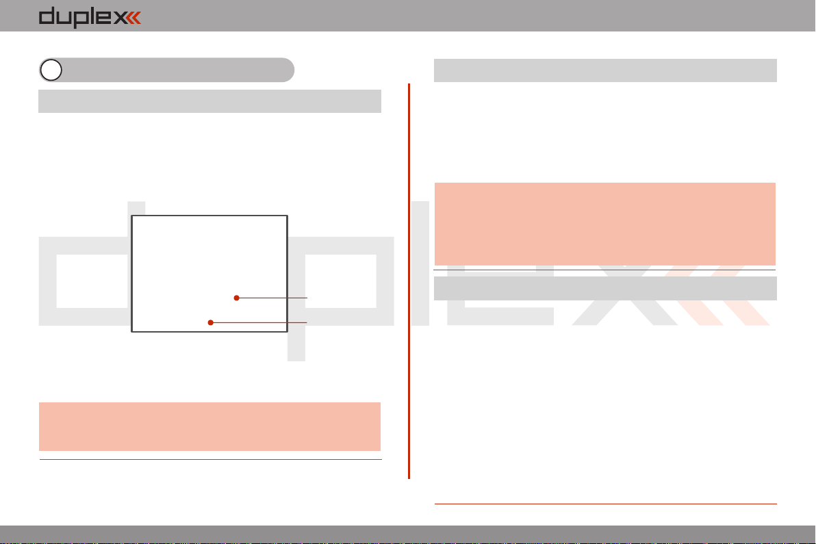
The Desktop is the largest part of the screen. This is where you can
see your telemetry data and where any programmed alarms are
displayed. The Desktop displays your user-defined information
through the use of multiple pages. As you add or remove telemetry
items or alarms, the number of available pages will automatically
increase or decrease as needed.
In this example, the desktop page displays the following
information: 7. Throttle Lock (FIX THE NUMBER)
8. Motor cut-off indication, idle
1
2
3
4
5

computer radio control system EN
7.2. Navigation in the Menu
3.3.
To navigate within the transmitter menus, use the following
buttons:
1. The „menu“ button allows you to switch between the main
display and the transmitter‘s main menu. Also, If you push this
button while turning the 3D Control Selector to edit values, the
values can be changed faster. With the menu button pressed,
10 more values are changed per turn.
2. The „esc“ button allows you to move one level back within the
menu. If you push this button while you are editing a value you
will return one menu level and the edited value will NOT be
stored.
3. 3D Control Selector
3a - by turning the selector anticlockwise you will move up
in the menu. Turning the selector this direction will also
decrease any value you are editing.
- by turning the selector clockwise you will move down in 3b
the menu. Turning the selector this direction will also
increase any value you are editing.
by pressing the selector you will confirm your 3c
choice/enter the selected menu.
4. The „F1 - F5“ functions buttons located below the display are
used to select various options based upon the current display.
1
3
23b
3a
3c
7.2.1 Browsing through the Menu
The current selection within the menu (cursor) is designated by
reversed text/shaded graphics. By turning the 3D control selector
left/right you will move through the lines of a menu.
To select an item, first highlight the line and then press the „3D
button“, to select the line. Rotate the the 3D control selector to
highlight your selected item within the line then press the „3D
button“ to select the item. Rotate the 3D control selector either left
or right to change the value of your chosen item. By pressing the
„3D button“ again you will confirm the storage of your selected
value and go back to your previously selected menu item. If you
want to go back to select another line within the previous menu
press the „esc“ button.
Note: For each press of the „esc“ button, you are taken back one
menu level.
4
Table of contents
Other Jeti Transmitter manuals

Popular Transmitter manuals by other brands


Epever
Epever RTU 2G A manual

Evikon
Evikon PluraSens E2618-N2O user manual

Magnetrol
Magnetrol ES Modulevel Installation and operating manual

AMG-Sicherheitstechnik
AMG-Sicherheitstechnik NR-03 IMPORTANT NOTE

Martin Lehmann
Martin Lehmann TXRF24B4 operating instructions

SMAR
SMAR DT303 Owner's operation and maintenance manual


