JetLegend T-45 Goshawk
Page 4 of 24
BEFORE YOU BEGIN
Keep this in mind as you proceed:
Look at EVERY assembly step you finish,
and ask yourself:
"Is this going to crash my airplane?"
A chain is only as strong as its weakest link,
and this is a high-performance aircraft that
will be very intolerant of sloppy assembly
techniques. Even the smallest component is
important and can cause the loss of your
airplane, so take the time to do things right.
Or REdo them if they are wrong. Careful work
will result in a long-lasting plane that gives
you years of pleasure, one loose component
could result in the complete loss of the
aircraft and all the components inside it, and
someone can even get hurt. So pause every
once in a while when building it and
double-check your workmanship.
TOOLS AND ADHESIVES
Some useful tools for assembly will
be a screw gun for drilling holes and a dremel
tool with a 90 degree attachment, and some
high quality screwdrivers. Not much else is
needed. Two allen wrenches are provided
with the kit that fit all the bolts.
As far as adhesives go, Loctite Hysol is the
strongest and best epoxy for installing the
components, but if you cannot get any, 30
minute epoxy will do. Avoid five minute
epoxy, it is not nearly as strong as the 30
minute kind, and it gives you much more time
to properly align things before it sets.
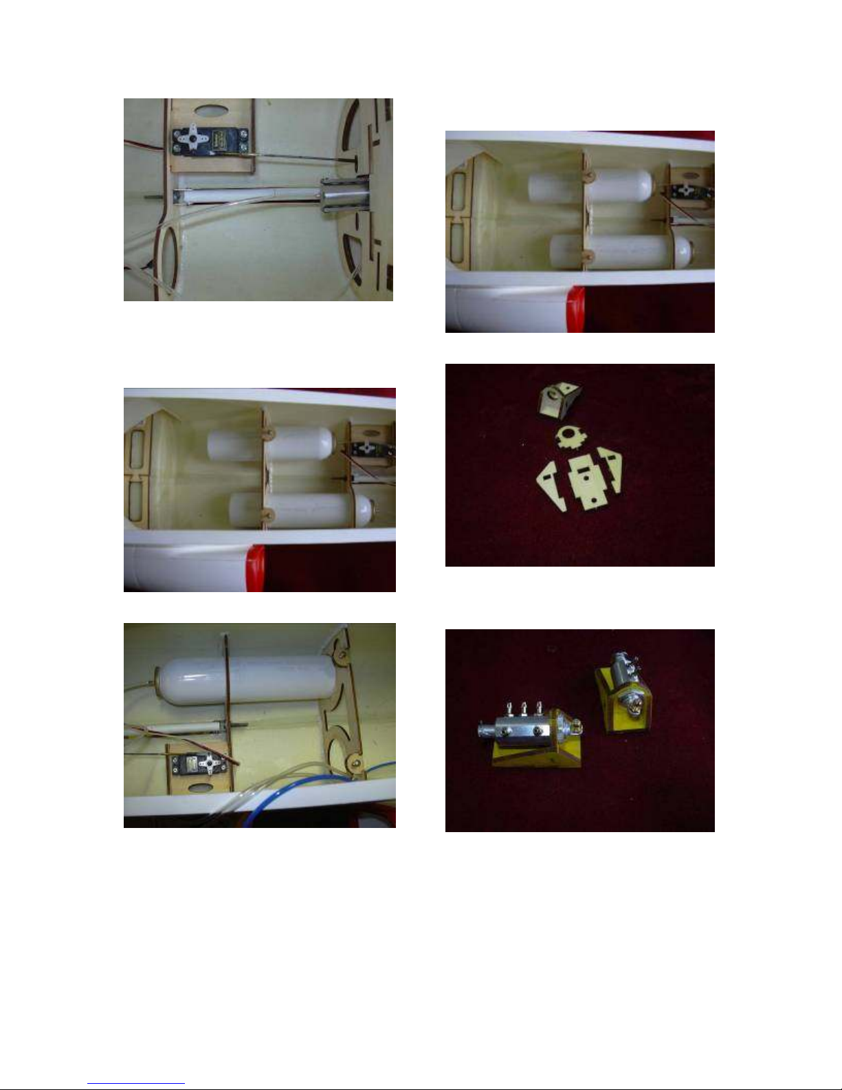
PNEUMATIC AND FUEL SYSTEMS
All tubing joints must be cut off very square to
avoid leaks. Do not clip them with scissors or
cutters or you will get an angled, leak-prone
end on the tubing. Use a very new razor and
cut all joints dead straight for best results.
When you are done, your air systems should
hold air overnight at the very least...for
months is even better. Any leaks are
unacceptable, it will be a matter of time
before you are damaging your aircraft with a
gear-up, or even worse, a one- or two- gear
landing, so take your time and track down
any leaks, no matter how slight, before flying.
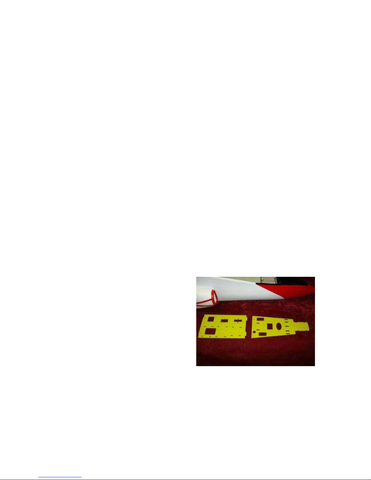
RADIO INSTALLATION
There are enormous variations in
how you can set up your radio trays. You
may or may not use dual power switches, a
power distribution box for servos, battery
backers, smoke pumps, etc., according to
your personal tastes. If you like, you can cut a
new blank tray if the factory-made cutouts do
not suit your installation. What is shown here
is just some basic guidelines of how some of
the necessary systems are installed, but
where exactly you want to install them is up
to you. Just make sure all components are
well-secured with tie-wraps or Velcro, and
that the turbine ECU and fuel pump are kept
well away from the receiver so as not to get
any radio interference.
There are great variations in servo
choices and how the servos are mounted.
Some may come with flat mounts, feel free to
use them. Whatever way you mount your
servos, be sure to mount them SECURELY.
Any play may result in flutter and the loss of
your aircraft. The aluminum mounts and
plywood blocks provided in the kit can be
modified accordingly to suit the servos you
chose. Do not use rubber servo grommets,
they are to dampen the vibration of a glow
engine, turbine engines produce no vibration,
so all the grommets will do is allow the servo
to move and lead to potential flutter. Digital
servos are highly recommended on all flight
controls, as are servos with metal gears.
Plastic gears can chip a tooth if the control
surface is bumped while assembling the
aircraft at the field, and it's too easy for this
situation to go unnoticed until the servo fails
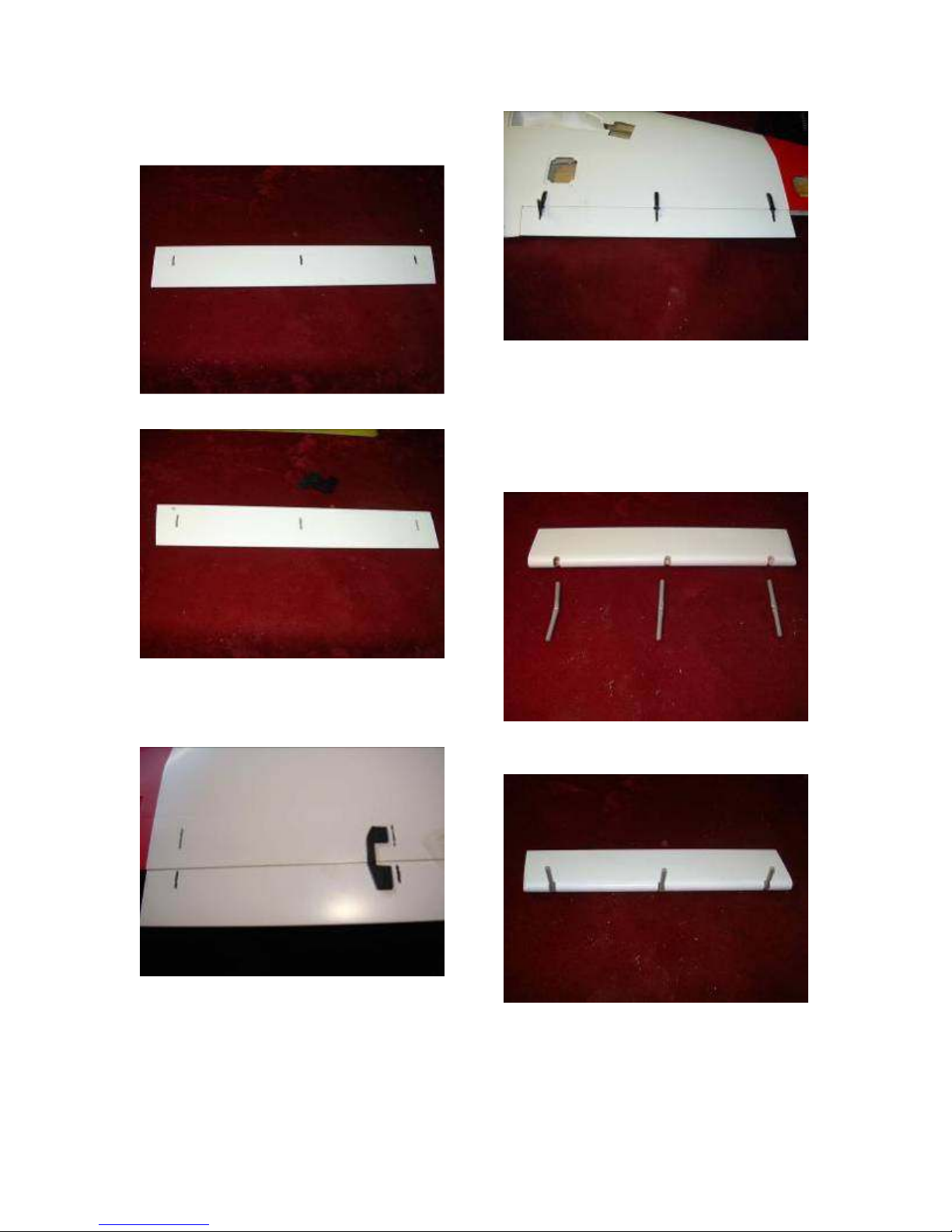
in the air. Metal servo arms are also good
insurance against flutter. The linkages and
fiberglass control horns provided in the kit are
extremely strong, there is no need to replace
them with aftermarket ones. Be sure to use
all the provided retention hardware, including
the tiny circlips. They are all there for a
reason. The horns on your servos and the
holes in the fiberglass control horns provided
in the kit may need to be drilled out to
accommodate the clevis pins. It's easier to
do this to all of the horns before any
assembly. Do this carefully, and discard
anything with an oversized hole, as any slop
here is unacceptable.
It is highly recommended that all
servos be "burned in" for an hour or so before
installation, using a servo driver to excercise