JetNet 3008 Series User manual

Tel:+886-2-82193000
Fax:+886-2-82193300
CPQ000N3008000
V0.2
JetNet 3008 / 3008f Series
www.korenix.com
Quick Installation Guide
Industrial Ethernet Switch

2. ܝ㑪ප䗷(JetNet 3008f) : ᇛܝ㑪㎮ϔッ䗷JetNet 3008f ܝ㑪පˈϔッ䗷䳔ܹⱘܝ
㑪ප䀁٭ˈབϟ೪᠔⼎DŽ䤃䁸ⱘ䗷㎮᳗ᇢ㟈ܝ㑪ප⛵⊩ᎹDŽ
Korenix ଂᕠ᳡ࢭ
KoreCAREᰃᚴ䗮⾥ᡔܼ⧗ᅶ᠊᳡ࢭЁᖗˈ䊛⏅ᡔ㸧Ҏવ䱼ᰖ⚎ᙼᦤկᇜὁⱘᡔ㸧ᬃᣕDŽ
DIP ℶ᩹䭟䮰䀁ᅮ
Ǽ
䗭ᰃϔℒClass 1 䨇ᇘ/LED ⫶કDŽ
ߛ࣓Ⳉ㽪䨇ᇘܝᴳDŽ
⊼ᛣ
RX
TX
RX
TX
Cable Wiring(SC to SC)
RX A TX B
TX A RX B
P1 to P8
(Pin1 ~ 8)
P9
Pin No. # ⢔ᜟ ᦣ䗄
ON ଳࢩ䁆ッষⱘᮋ㎮ฅ䄺ࡳ㛑
ON ଳࢩᮋ䳏ฅ䄺ࡳ㛑
Off 䮰䭝䁆ッষⱘᮋ㎮ฅ䄺ࡳ㛑
Off 䮰䭝ᮋ䳏ฅ䄺ࡳ㛑
JetNet 3008/3008f Industrial Ethernet Switch, conforming IEEE 802.3 and 802.3u standard,
supports 8 10/100Base TX (JetNet 3008) or 6 10/100TX plus two 100FX Fast Ethernet fiber
ports in either multi-mode type (JetNet 3008f-m) or single-mode type (JetNet 3008f-s).
The JetNet3008/3008f adopts rugged metal case design to operate in harsh environments
(-25oC~70oC); It also provides IP-30 standard protection. It features one relay output to alarm
users if a port link fails or with the power fails. Alarms can be enabled/disabled by a 9-pin dip
switch. JetNet 3008/3008f is recommended to be powered by DC 24V with 12~48V range
from the 6-pin removable terminal block.
Introduction
Box contents
�
JetNet 3008/3008f Switch
�
Quick Installation Guide
�
CD User Manual
Mounting the Unit
�
Din-Rail mount: Mount the din-rail clip
screwed on the rear of JetNet 3008/3008f on the DIN rail.
About the DIN Rail installation, please refer
user’s manual.
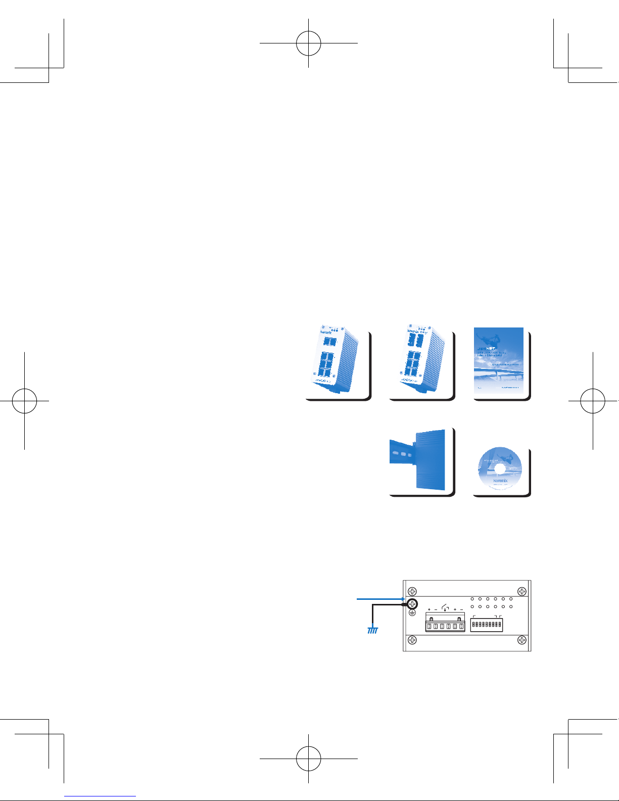
Grounding JetNet 3008 / 3008f Switch
There is one grounding screw on the bottom side
of JetNet 3008/3008f. Connect the earth ground
screw of switch to the grounding surface to ensure
safety and prevent noise. See, Figure-1
Package contents Check List
PW1
Alm
PW2
Alarm Control
port 1~8 power
Earth Ground
Screw
Earth Ground
Warning: Do not connect to AC line-Natural
Figure-1

Wiring the Power Inputs
1. Insert the positive and negative wires into the
V+ and V- contact on the terminal block connector.
2. Tighten the wire-clamp screws to prevent the DC
wires from being loosened. See Figure-2
Notes: The recommended working voltage is DC24V (DC12~ 48V).
The relay output alarm contacts are in the middle
of the terminal block connector as shown in the
figure below.
By inserting the wires and set the DIP switch of the
respective Port Alarm to “ON”, relay output alarm will
detect any port failures, and form a short circuit.
The alarm relay output is “Normal Open”. See, Figure -3.
Wiring the Earth Ground
In an industrial environment, there might have
a lot of devices that generate electromagnetic
noise, such as AC motors, electric welding
machine, power generator. These devices will
generate electric noise or surges that might
disturb communications. To prevent those noises,
the switch should be well earthed.
In the figure- shows how to make connection. See, Figure -4.
Wiring the Relay Output
Maximum 1A current / DC 24V
Figure-3
PW1
Alm
PW2
Alarm Control
port 1~8power
Alarm
System
Extra Power
System
PW1
Alm
PW2
Alarm Control
port 1~8power
Earth Ground
Screw
Earth Ground
Warning: Do not connect to AC line-Natural
Figure-4
Figure-2

Connecting to Network
1. Connecting the Ethernet Ports: Connect one end of an Ethernet cable into the UTP port of
JetNet 3008/3008f, while the other end is connected to the attached networking device. All
UTP ports support auto MDI/MDIX function. The Speed LED will turn on for 100M link and
turn off for 10Mbps link, the LNK/ACT LED will turn on for link up and blinking for packet
transmit and receive. The fiber port only support 1 LED for Link and Activity.
2. Connecting the Fiber Port (JetNet 3008f) : Connect the fiber port on your JetNet 3008f to
another Fiber Ethernet device, by following the figure below. Wrong connection will cause the
fiber port not working properly
.
Korenix Customer Service
KoreCARE is Korenix Technology’s global service center, where our professional staff are
ready to solve your problems at any time
DIP Switch Settings for Alarm Relay Output
Ǽ
This is a Class 1 Laser/LED product.
Don't stare into the Laser/LED Beam.
ATTENTION
RX
TX
RX
TX
Cable Wiring(SC to SC)
RX A TX B
TX A RX B
P1 to P8
(Pin1 ~ 8)
P9
Pin No. # StatusDescription
ON To enable port link down alarm at this port.
ON To enable power failure alarm.
Off To disable port link down alarm at this port.
Off To disable power failure alarm.

JetNet 3008/3008f ᎹϮҹ㔥Ѹᤶᴎˈヺড়IEEE 802.3802.3uޚˈᬃᣕ8Ͼ10/100Base
TXッষ(JetNet 3008)6Ͼ10/100TXッষࡴ2Ͼ100FX ᖿ䗳ҹ㔥ܝষˈᑊᦤկܝষൟো
(JetNet 3008f-m)ܝষൟো(JetNet 3008f-s)ৃ䗝DŽJetNet 3008/3008f Ѹᤶᴎ䞛⫼മⱘ
䪱ড়䞥㒧ᵘ䆒䅵ˈ㛑ᙊࡷⱘᎹϮ⦃๗(-25~70oC)〇ᅮᎹˈヺড়IP31ᎹϮ䰆ᡸޚDŽ
ᅗ䖬ᬃᣕϔ䏃㒻⬉఼䄺䕧ߎˈৃ䩜ᇍᮁ㒓/ᮁ⬉⢊ᗕᦤկ⦄എ䄺᳡ࡵDŽℸ㒻⬉఼䄺ࡳ㛑ৃ
䗮䖛Ѹᤶᴎࠡ䴶ᵓⱘDipᢼⷕᓔ݇ࡼ݇䯁DŽJetNet 3008/3008f ᴎ䑿ᑩ䚼㺙᳝ৃᢚ⬉⑤
㒓ῑˈ݊䕧ܹ⬉⑤㣗ೈᰃ12~48V ˈᓎ䆂䞛⫼〇ᅮⱘ24VⳈ⌕⬉Ў䆒կ⬉DŽ
ὖ䗄
ࣙ
�
JetNet 3008/3008f Ѹᤶᴎ
�
ᖿ䗳ᅝ㺙ᇐ
�
⫼᠋ݠCDⲬ
ᅝ㺙䜡ӊ
�
ᇐ䔼ᅝ㺙˖⫼㶎ϱᇚᇐ䔼།ᅮJetNet 3008/3008f
ᴎ䑿㚠䴶ˈ✊ৢᇚᇐ䔼།Ϟᇐ䔼DŽ
ᇐ䔼ᅝ㺙䆺ᚙˈ䇋খⳟ⫼᠋᪡ݠ
JetNet 3008 / 3008f ഄ㒓䖲
JetNet 3008/3008fᴎ䑿ᑩ䚼᳝ϔϾഄ㒓䖲㶎↡DŽ
ᇚѸᤶᴎⱘഄ㒓㶎↡ഄˈৃ⹂ֱ䆒Փ⫼ᅝܼˈ
ᡫᴖ䆃ᑆᡄDŽখⳟ-1
ѻક䚼ӊ⏙
PW1
Alm
PW2
Alarm Control
port 1~8 power
Earth Ground
Screw
Earth Ground
Warning: Do not connect to AC line-Natural
-1

⬉⑤䖲
1. ᇚ⬉⑤ⱘℷ䋳ᵕᇐ㒓ߚ߿ᦦܹᴎ䑿ᑩ䚼⬉⑤㒓ῑ
ⱘV+ V- 㛮DŽ
2. ᇚ㒓།ᢻ㋻ˈ䰆ℶDC⬉⑤㒓ᤃࡼ㜅㨑DŽখⳟ-2
⊼⬉㣗ೈ(DC12~ 48V)ˈᓎ䆂⬉DC24VDŽ
㒻⬉఼䄺䕧ߎ䖲⚍ᰃ⬉⑤㒓ῑⱘЁ䭧ⱘϔᇍ
㛮ˈ བЁ᠔⼎ԡ㕂DŽ
䖲ᇐ㒓ˈᑊᇚᇍᑨッষⱘDIPᢼⷕᓔ݇㕂“ON”ˈ
㒻⬉఼䄺ࡳ㛑֓ৃҹẔ⌟ࠄッষᮁ䖲ˈᑊᔶ៤ϔ
Ͼ⬉⑤ಲ䏃DŽℷᐌᚙމϟˈ㒻⬉఼䄺㒓䏃ᰃᓔ䏃
⢊ᗕDŽখⳟ-3.
ഄ㒓䖲
ᎹϮ⦄എ⦃๗Ёˈৃ㛑Ӯ᳝䞣ѻ⫳⬉⺕ᑆᡄ
ⱘ䆒ᄬˈབѸ⌕⬉ࡼᴎˈ⬉⛞ᴎˈথ⬉ᴎDŽ
䖭ѯ䆒ѻ⫳ⱘ⬉⺕ᑆᡄ⌾⍠ᑆᡄഛৃ㛑ഛㅨ
ӷℷᐌ䗮䆃DŽЎ䰆ℶᑆᡄᕅડˈ䇋ᇚѸᤶᴎℷ⹂
ഄDŽ4ᦤկℷ⹂䖲㒓⼎՟DŽ
㔥㒓䖲
1. ҹ㔥䖲˖ᇚUTPঠ㒲㒓ⱘϔッ䖲JetNet 3008/3008fҹ㔥⬉ষˈϔッ䖲ࠄ䳔ܹ
ⱘ㔥㒰䆒DŽ᠔᳝UTPッষᬃᣕ㞾䗖ᑨMDI/MDIXDŽᔧЎ100M䖲㒓ᯊˈ䗳⥛LEDᣛ⼎♃Ӯ҂䍋
ˈᔧЎ10M䖲㒓ᯊˈᣛ⼎♃Ӯ❘♁DŽLNK/ACT LEDᣛ⼎♃҂䍋㸼⼎ッষᏆ㒣䖲㒓ˈֵো♃䮾⚕
㸼⼎䆹ッষℷᬊথ᭄DŽܝষLEDᣛ⼎♃া᳝ϔϾˈᰒ⼎䖲㒓⢊ᗕ⌏ࡼ⢊ᗕDŽ
㒻⬉఼䄺䕧ߎ䖲㒓
Maximum 1A current / DC 24V
PW1
Alm
PW2
Alarm Control
port 1~8 power
Alarm
System
Extra Power
System
PW1
Alm
PW2
Alarm Control
port 1~8 power
Earth Ground
Screw
Earth Ground
Warning: Do not connect to AC line-Natural
-2
-3
-4

2. ܝষ䖲(JetNet 3008f) : ᇚܝ㑸㒓ϔッ䖲JetNet 3008f ܝষˈϔッ䖲䳔ܹⱘܝষ䆒
ˈབϟ᠔⼎DŽ䫭䇃ⱘ䖲㒓Ӯᇐ㟈ܝষ᮴⊩ᎹDŽ
Korenix ଂৢ᳡ࡵ
KoreCAREᰃ㢃ᚴ䗮⾥ᡔܼ⧗ᅶ᠋᳡ࡵЁᖗˈ䌘⏅ᡔᴃҎ䱣ᯊЎᙼᦤկϧϮⱘᡔᴃᬃᣕDŽ
Korenix㢃ᚴ䗮ܼ⧗ଂৢ᳡ࡵЁᖗ⬉ᄤ䚂ӊ˖[email protected]
DIP ᢼⷕᓔ݇䆒ᅮ
Ǽ
䖭ᰃϔℒClass 1 ▔ܝ/LED ѻકDŽ
ߛ࣓ޱ㾚▔ܝܝᴳDŽ
⊼ᛣ
RX
TX
RX
TX
Cable Wiring(SC to SC)
RX A TX B
TX A RX B
P1 to P8
(Pin1 ~ 8)
P9
Pin No. # ⢊ᗕ ᦣ䗄
ON ࡼ䆹ッষⱘᮁ㒓䄺ࡳ㛑
ON ࡼᮁ⬉䄺ࡳ㛑
Off ݇䯁䆹ッষⱘᮁ㒓䄺ࡳ㛑
Off ݇䯁ᮁ⬉䄺ࡳ㛑

JetNet 3008/3008f ᎹὁЭ㎆Ѹ఼ˈヺড়IEEE 802.3802.3u῭⑪ˈᬃᣕ8ן10/100Base
TXප(JetNet 3008)6ן10/100TXපࡴ2ן100FX ᖿ䗳Э㎆ܝ㑪පˈϺᦤկܝ㑪පൟ㰳
(JetNet 3008f-m)ஂܝ㑪පൟ㰳(JetNet 3008f-s)ৃ䙌DŽJetNet 3008/3008f Ѹ఼⫼ෙ
ⱘ䢕ড়䞥←ᶊᾟ䀁㿜ˈ㛑ᚵࡷⱘᎹὁ⪄๗(-25~70OC)〽ᅮᎹˈヺড়IP31Ꮉὁ䰆䅋῭⑪
DŽᅗ䙘ᬃᣕϔ䏃㑐䳏఼ฅ䄺䔌ߎˈৃ䞱ᇡᮋ㎮/ᮋ䳏⢔ᜟᦤկ⧒จฅ䄺᳡ࢭDŽℸ㑐䳏఼ฅ䄺ࡳ㛑
ৃ䗣䘢Ѹ఼ࠡ䴶ᵓⱘDip止᩹䭟䮰ଳࢩ䮰䭝DŽJetNet 3008/3008f ″䑿ᑩ䚼㺱᳝ৃᢚ䳏
⑤㎮ῑˈ݊䔌ܹ䳏⑤㆘ೡᰃ12~48V ˈᓎ䅄⫼〽ᅮⱘ24VⳈ⌕䳏⚎䀁٭կ䳏DŽ
ὖ䗄
ࣙ
�
JetNet 3008/3008f Ѹ఼
�
ᖿ䗳ᅝ㺱ݞ
�
Փ⫼ݞCD
ᅝ㺱䜡ӊ
�
ᇢ䒠ᅝ㺱Ή⫼㶎㍆ᇛᇢ䒠༒ᅮJetNet 3008/3008f
″䑿㚠䴶ˈ✊ᕠᇛᇢ䒠༒Ϟᇢ䒠DŽ
ᇢ䒠ᅝ㺱䁇ᚙˈ䂟গⳟՓ⫼᪡ݞ
JetNet 3008 / 3008f ഄ㎮䗷
JetNet 3008/3008f″䑿ᑩ䚼᳝ϔןഄ㎮䗷㶎↡DŽ
ᇛѸ఼ⱘഄ㎮㶎↡ഄˈৃ⺎ֱ䀁٭Փ⫼ᅝܼˈ
ᡫ䲰㿞ᑆDŽগⳟ೪
⫶ક䚼ӊ⏙ஂ
PW1
Alm
PW2
Alarm Control
port 1~8 power
Earth Ground
Screw
Earth Ground
Warning: Do not connect to AC line-Natural
೪-1

䳏⑤䗷
1. ᇛ䳏⑤ⱘℷ䉴Ὁᇢ㎮ߚ߹ᦦܹ″䑿ᑩ䚼䳏⑤㎮ῑ
ⱘV+ V- 㝇DŽ
2. ᇛ㎮༒㎞ˈ䰆ℶDC䳏⑤㎮ᤃࢩ㛿㨑DŽগⳟ೪-2
٭⊼: 䳏ວ㆘ೡ(DC12~ 48V)ˈᓎ䅄䳏ວDC24VDŽ
㑐䳏఼ฅ䄺䔌ߎ䗷咲ᰃ䳏⑤㎮ῑЁ䭧ⱘϔᇡ
㝇ˈབ೪Ё᠔⼎ԡ㕂DŽ
䗷ᇢ㎮ˈϺᇛᇡឝッষⱘ',3ℶ᩹䭟䮰㕂“ON”ˈ
㑐䳏఼ฅ䄺ࡳ㛑֓ৃҹ⁶␀ࠄッষᮋ䗷ˈϺᔶ៤ϔ
ן䳏⑤ಲ䏃DŽℷᐌᚙ⊕ϟˈ㑐䳏఼ฅ䄺㎮䏃ᰃ䭟䏃
⢔ᜟDŽগⳟ೪-3DŽ
ഄ㎮䗷
Ꮉὁ⧒จ⪄๗Ёˈৃ㛑᳗᳝䞣⫶⫳䳏⺕ᑆⱘ
䀁٭ᄬˈབѸ⌕侀䘨ˈ䳏⛞″ˈⱐ䳏″DŽ䗭ѯ
䀁٭⫶⫳ⱘ䳏⺕ᑆさ⊶ᑆഛৃ㛑ᑆࠄℷᐌ
䗮㿞DŽ⚎䰆ℶᑆᕅ䷓ˈ䂟ᇛѸ఼ℷ⺎ഄDŽ
೪4ᦤկℷ⺎䗷㎮⼎՟DŽ
㎆㎮䗷
1. Э㎆䗷ΉᇛUTP䲭㌲㎮ⱘϔッ䗷JetNet 3008/3008fЭ㎆䳏ষˈϔッ䗷ࠄ䳔ܹ
ⱘ㎆䏃䀁٭DŽ᠔᳝UTPッষᬃᣕMDI/MDIXDŽ⭊⚎100M䗷㎮ᰖˈ䗳⥛LEDᣛ⼎➜᳗҂䍋ˈ⭊⚎
10M䗷㎮ᰖˈᣛ⼎➜᳗❘⒙DŽLNK/ACT LEDᣛ⼎➜҂䍋㸼⼎ッষᏆ㍧䗷㎮ˈֵ㰳➜䭗⟡㸼⼎䁆
ッষℷᬊⱐᭌDŽܝ㑪පLEDᣛ⼎➜া᳝ϔןˈ乃⼎䗷㎮⢔ᜟ⌏ࢩ⢔ᜟDŽ
㑐䳏఼ฅ䄺䔌ߎ䗷㎮
Maximum 1A current / DC 24V
PW1
Alm
PW2
Alarm Control
port 1~8 power
Alarm
System
Extra Power
System
PW1
Alm
PW2
Alarm Control
port 1~8 power
Earth Ground
Screw
Earth Ground
Warning: Do not connect to AC line-Natural
೪-2
೪-3
೪-4

2. ܝ㑪ප䗷(JetNet 3008f) : ᇛܝ㑪㎮ϔッ䗷JetNet 3008f ܝ㑪පˈϔッ䗷䳔ܹⱘܝ
㑪ප䀁٭ˈབϟ೪᠔⼎DŽ䤃䁸ⱘ䗷㎮᳗ᇢ㟈ܝ㑪ප⛵⊩ᎹDŽ
Korenix ଂᕠ᳡ࢭ
KoreCAREᰃᚴ䗮⾥ᡔܼ⧗ᅶ᠊᳡ࢭЁᖗˈ䊛⏅ᡔ㸧Ҏવ䱼ᰖ⚎ᙼᦤկᇜὁⱘᡔ㸧ᬃᣕDŽ
Korenixᚴ䗮ܼ⧗ଂᕠ᳡ࢭЁᖗ䳏ᄤ䛉ӊΉ[email protected]
DIP ℶ᩹䭟䮰䀁ᅮ
Ǽ
䗭ᰃϔℒClass 1 䨇ᇘ/LED ⫶કDŽ
ߛ࣓Ⳉ㽪䨇ᇘܝᴳDŽ
⊼ᛣ
RX
TX
RX
TX
Cable Wiring(SC to SC)
RX A TX B
TX A RX B
P1 to P8
(Pin1 ~ 8)
P9
Pin No. # ⢔ᜟ ᦣ䗄
ON ଳࢩ䁆ッষⱘᮋ㎮ฅ䄺ࡳ㛑
ON ଳࢩᮋ䳏ฅ䄺ࡳ㛑
Off 䮰䭝䁆ッষⱘᮋ㎮ฅ䄺ࡳ㛑
Off 䮰䭝ᮋ䳏ฅ䄺ࡳ㛑

Die JetNet 3008/3008f Industrial Ethernet Switches entsprechen dem IEEE 802.3 und 802.3u
Standard. Sie bieten 8 x 10/100Base TX (JetNet 3008) oder 6 x 10/100TX + 2 x 100FX Fast
Ethernet LWL-Anschlüsse (JetNet 3008f), entweder als Multi-Mode Typ (JetNet 3008f-m)
oder Single-Mode Typ (JetNet 3008f-s). Der JetNet 3008/3008f bietet ein robustes
Metallgehäuse (IP-30) für den Betrieb in einer rauen Umgebung (-25~70OC). Wenn die
Versorgungsspannung oder ein Port ausfällt, wird über einen Relaisausgang ein Alarm
ausgegeben. Dieser Alarm kann über DIP-Schalter ein- oder ausgeschaltet werden. Als
Versorgungsspannung sind 12~48VDC erforderlich. Empfohlen werden 24VDC, die an einem
6-PIN abnehmbaren Schraubklemmbock angeschlossen werden.
Einführung
Die Lieferung besteht aus
�
JetNet 3008/3008f Switch
�
Quick Installation Guide
�
CD mit Handbuch
Montageanleitung
�
Hutschienenmontage: Haken Sie den auf der Rückseite
des JetNet 3008/3008f befindlichen Hutschienen-Clip auf
der Hutschiene ein.
Weitere Informationen zur Hutschienenmontage entnehmen Sie bitte dem Handbuch
Erdung des JetNet 3008 / 3008f Switches
An der Unterseite des JetNet 3008/3008f befindet
sich die Erdungs-Schraube. Verbinden Sie den
Switch mit einem geeigneten Erdanschluss.
Abbildung 1
Packungsinhalt
PW1
Alm
PW2
Alarm Control
port 1~8 power
Earth Ground
Screw
Earth Ground
Warning: Do not connect to AC line-Natural
Abbildung 1

Anschluss der Spannungsversorgung
1. Verschrauben Sie Leitungen der Netzteile gemäß
nebenstehender Abbildung. Abbildung 2
2. Achten Sie darauf, die Schrauben fest anzuziehen.
Hinweis: Versorgungsspannung beträgt
DC24V (DC12~ 48V).
Der Relaisausgang für den Alarm befindet sich in der
Mitte der Steckerleiste (siehe Skizze).
Bei angeschlossener Leitung und über DIP-Schalter
aktiviertem Alarm, reagiert er auf Unterbrechungen
bei den Ports und der Versorgungsspannung.
Die Werkseinstellung ist „Alarm Aus“. Abbildung 3.
Anschluss der Erde
Im industriellen Umfeld können eine Menge an
EMV-Störungen auftreten. Diese können von
Wechselstrommotoren, E-Schweißautomaten
oder Generatoren stammen. Solche Geräte
erzeugen EMV-Störungen oder Spannungsspitzen,
die unter Umständen die Kommunikation stören
können. Zum Schutz vor solchen Störungen,
sollte der Switch geerdet werden. Abbildung 4
Verdrahtung des Relaisausgangs
Maximum 1A current / DC 24V
PW1
Alm
PW2
Alarm Control
port 1~8 power
Alarm
System
Extra Power
System
PW1
Alm
PW2
Alarm Control
port 1~8 power
Earth Ground
Screw
Earth Ground
Warning: Do not connect to AC line-Natural
Abbildung 2
Abbildung 3
Abbildung 4

Anschluss an das Netzwerk
1. Anschluss des Ethernet Ports: Stecken Sie den RJ-45 Stecker des einen Endes des
Ethernetkabels in den UTP Port des JetNet 3008 / 3008f, und verbinden Sie das andere
Ende des Kabels mit dem entsprechenden Netzwerk-Gerät. Alle UTP Ports unterstützen Auto
MDI/MDIX. Die Geschwindigkeits-LED leuchtet bei einer 100M Verbindung und ist bei einer
10Mbps Verbindung aus. Die LNK/ACT LED leuchtet bei einer funktionierenden Verbindung
und blinkt beim Empfang oder Versand von Datenpaketen. Der LWL Port unterstützt nur 1
LED für Link and Activity.
2. Anschluss des LWL Ports (JetNet 3008f) : Verbinden Sie den LWL-Port Ihres JetNet 3008f
mit dem anderen LWL-Gerät. Beachten Sie dabei nebenstehende Abbildung Ein falscher
Anschluss des LWL führt zu einer fehlerhaften Verbindung.
Korenix Kundenservice
KoreCARE ist ein weltweites Korenix Technology’s Servicecenter, wo Ihnen zu jeder Zeit
fachkundige Mitarbeiter bei der Lösung Ihrer Probleme behilflich sind.
DIP Schalter-Stellung für den Relais-Alarmausgang
Ǽ
Dies ist ein Class 1 Laser/LED Produkt.
Nicht in den Laser/LED Strahl schauen
ATTENTION
RX
TX
RX
TX
Cable Wiring(SC to SC)
RX A TX B
TX A RX B
P1 to P8
(Pin1 ~ 8)
P9
Pin No. # StatusBeschreibung
ON Alarm “Ein” bei Verbindungsverlust auf diesem Port
ON Alarm “Ein” bei Unterbrechung der Spannungsversorgung
Off Alarm “Aus” bei Verbindungsverlust auf diesem Port
Off Alarm “Aus” bei Unterbrechung der Spannungsversorgung
Les switchs Industriels Ethernet JetNet 3008/3008f sont conformes aux normes IEEE 802.3
et 802.3u. Ils proposent 8 ports 10/100Base TX (JetNet 3008) ou 6 ports 10/100TX plus 2
ports 100FX Fibre Ethernet Rapide en multi-mode type (JetNet 3008f-m) ou single-mode type
(JetNet 3008f-s). Les JetNet 3008/3008f sont intégrés dans un Boitier métallique pour
supporter les environnements industriels et ils peuvent fonctionner dans une plage de
température de (-25~70oC. Ils proposent aussi en standard une protection IP-30. Une alarme
par relais permet d’alerter les utilisateurs dans le cas de défauts de communication ou
d’alimentation. Les alarmes peuvent être désactivées par dip switch. L’alimentation des 3008/
3008f est de 24V DC avec une plage de 12 à 48V et une connectique par bornier amovible.
Introduction
�
Switch JetNet 3008/3008f
�
Guide Installation Rapide
�
CD Manuel Utilisateur
Montage du Switch
�
Montage duRail-Din: Monter le Rail-Din par les vis de
fixation à l’arrière du Jetnet, ensuite vous pouvez clipser
l’unité sur le Rail.
Au sujet de l'installation du Rail-Din, vous pouvez
faire référence au manuel d'utilisateur.
Raccordement à la Masse du JetNet3008 / 3008f
Il y a une vis sur le côté inférieur du switch qui permet
le raccordement à la masse pour assurer la sécurité
et prévenir des problèmes de bruit électromagnétique.
Voir, Figure-1
Liste du Package
PW1
Alm
PW2
Alarm Control
port 1~8 power
Earth Ground
Screw
Earth Ground
Warning: Do not connect to AC line-Natural
Figure-1

Cablâge de l’alimentation
1. Insérer les fils d’alimentation dans les bornes
positive (V+) et négative (V-) du bornier de raccordement.
2. Serrez les vis pour bloquer les fils. Voir Figure-2
Note: Il est recommandé d’utiliser une tension
de 24V DC(DC12~ 48V).
Le contact d’alarme du relais est positionné au milieu
du bornier de raccordement comme le montre le
croquis ci-dessous.
Raccordez les fils et placer le switch correspondant
sur ON. Une alarme se produira sur chaque défaut
et le contact sera actionné. L’état du contact est
" Normale Ouvert ". Voir Figure-3.
Cablâge de la Masse
Dans un environnement industriel, beaucoup
d’appareils peuvent produire un bruit
électromagnétique, tel que moteurs AC, poste de
soudure, générateur d’alimentation. Ces appareils
produisent un bruit important qui peut perturber
les communications. Pour prévenir ces problèmes,
le switch doit être raccordé à la masse.
Sur la figure 4, vous verrez comment réaliser cette connexion.
Cablâge du relais de sortie
Maximum 1A current / DC 24V
Figure-3
PW1
Alm
PW2
Alarm Control
port 1~8 power
Alarm
System
Extra Power
System
PW1
Alm
PW2
Alarm Control
port 1~8 power
Earth Ground
Screw
Earth Ground
Warning: Do not connect to AC line-Natural
Figure-4
Figure-2

Raccordement au réseau
1. Connexion des ports Ethernet : Connectez une extrémité Ethernet sur le port UTP du
JetNet 3008/3008f, et l’autre sur le périphérique attaché au réseau. Tous les ports UTP
supportent la fonction auto MDI/MDIX. Un voyant Led sera allumé si la vitesse du lien est de
100 Mb et sera éteint pour 10 Mb, le voyant LNK/ACT LED sera allumé pour signaler un lien
actif et clignotera pendant les transmissions et réceptions de paquets.
Seul le port fibre possède un voyant LED pour le lien et pour la signalisation de l’activité.
2. Connexion du Port fibre (JetNet 3008f) : Connectez le port fibre sur le JetNet 3008f et
l’autre extrémité à un périphérique Ethernet fibre, suivant l’image ci-dessous. Une mauvaise
connexion entrainera une communication défectueuse du port fibre.
Ǽ
This is a Class 1 Laser/LED product.
Don’t stare into the Laser/LED Beam.
ATTENTION
RX
TX
RX
TX
Cable Wiring(SC to SC)
RX A TX B
TX A RX B
DIP Switch Paramétrage Relais de sortie d’Alarme
Service après vente Korenix
KoreCARE est le service central de Korenix Technology’s, ou des professionnels sont prêt à
résoudre vos problèmes à tout moment.
P1 to P8
(Pin1 ~ 8)
P9
Pin No. # StatusDescription
ON Mise en fonction Alarme port de Communication
ON Mise en Fonction Alarme d’Alimentation
Off Mise hors fonction Alarme port de Communication
Off Mise hors fonction du défaut d’Alimentation

El switch ethernet industrial JetNet3008/3008f, conforme a los estándar IEEE 802.3 y 802.3u,
soporta 8 puertos 10/100 Base TX (JetNet 3008) o 6 puertos 10/100TX mas dos 100FX en
fibra multimodo (JetNet 3008f-m) o monomodo (JetNet 3008f-s). Incorpora un robusto chasis
metálico que posibilita temperaturas de trabajo extremas (-20º a 70º) al tiempo que ofrece
protección IP-30. Dispone de una salida por relé para alertar al usuario ante posibles fallos
en el link de un puerto o de alimentación. Dichas alarmas pueden ser habilitadas mediante
un DIP-switch de 9 pins. Para el JetNet 3008/3008f se recomienda una alimentación de 24V
DC, siendo su rango admisible entre 12 y 48V. Dicha alimentación se suministra a través de
un terminal removible de 6 pins.
Introducción
La caja contiene
�
Switch JetNet 3008 / 3008f
�
Guía de instalación rápida
�
Manual de usuario en CD
Montaje de la unidad
�
Montaje en carril DIN: Ajustar en el carril DIN el clip
instalado en la parte trasera del JetNet 3008/3008f
Para instalación en el carril DIN, por favor consulte el
manual de usuario
Conexión a tierra del JetNet 3008 / 3008f
Existe un tornillo de conexión a tierra en la parte
trasera del JetNet 3008/3008f. Utilice este tornillo
para unir el chasis a tierra por motivos de seguridad
y para prevenir ruido. Ver Fig. 1.
Contenido del embalaje
PW1
Alm
PW2
Alarm Control
port 1~8 power
Earth Ground
Screw
Earth Ground
Warning: Do not connect to AC line-Natural
Fig. 1

Conexión de la alimentación
1. Inserte las líneas positivo y negativo en los
terminales V+ y V- del conector de entrada.
2. Ajuste los tornillos del terminal para asegurar
la conexión (Ver Fig. 2)
Nota: El voltaje recomendado de trabajo es 24VDC (12-48 VDC)
Los contactos de la salida de alarma por relé se
encuentran en la parte central del bloque de conexión,
tal como se muestra en la figura.
Realizando las conexiones indicadas y configurando
el DIP Switch del puerto respectivo a ON, el relé
conectará sus terminales de salida ante cualquier
fallo en el puerto. La salida por relé es del tipo
“Normalmente Abierto” (Ver Fig. 3)
Conexión a Tierra
En un entorno industrial puede haber muchos
dispositivos que generen ruido electromagnético,
como por ejemplo motores AC, maquinas de
soldadura eléctrica o generadores de corriente.
Este ruido eléctrico o picos de tensión pueden
afectar a las comunicaciones.
Para prevenir esos efectos, el switch debería estar
correctamente conectado a tierra, tal como muestra la figura 4.
Cableado de la salida por relé
Maximum 1A current / DC 24V
Fig. 3
PW1
Alm
PW2
Alarm Control
port 1~8 power
Alarm
System
Extra Power
System
PW1
Alm
PW2
Alarm Control
port 1~8 power
Earth Ground
Screw
Earth Ground
Warning: Do not connect to AC line-Natural
Fig. 4
Fig. 2

Conexión a la red
1. Conectando los puertos ethernet: Conectar un extremo del cable ethernet al puerto UTP
del JetNet 3008/3008f y el otro al dispositivo a conectar a la red. Todos los puertos UTP
soportan la función auto MDI/MDIX. El led Speed se iluminará para conexiones a 100M y
permanecerá apagado para enlaces a 10M, el led LNK/ACT se ilumina al establecer el
enlace y parpadea con el envío y recepción de datos. El puerto de fibra dispone de un único
led para el enlace y la actividad del puerto.
2. Conectando los puertos de fibra (JetNet 3008f) : Conectar los puertos de fibra del JetNet
3008f a otro dispositivo ethernet siguiendo el esquema de la figura adjunta. Una conexión
errónea provocará un funcionamiento incorrecto en el puerto óptico.
Servicio Técnico Korenix
KoreCARE es el centro de servicio global de Korenix, donde nuestros profesionales se
encuentran disponibles para resolver sus problemas en cualquier momento. La dirección de
Configuración del DIP-switch para la salida de
alarma por relé
Ǽ
Esto es un dispositivo Láser/Led clase 1.
No mire fijamente el haz Láser/Led
ATTENTION
RX
TX
RX
TX
Cable Wiring(SC to SC)
RX A TX B
TX A RX B
P1 to P8
(Pin1 ~ 8)
P9
Pin No. #EstadoDescripción
ON Habilita alarma por pérdida de link en ese Puerto.
ON Habilita alarma por fallo en alimentación.
Off Deshabilita alarma por pérdida de link en ese Puerto.
Off Deshabilita alarma por fallo en alimentación.

Lo Switch Industriale Ethernet JetNet 3008/3008f , conforme agli standard IEEE 802.3 e
802.3u, supporta 8 porte 10/100Base TX (JetNet 3008) o 6 porte 10/100TX più due porte
fibra Fast Ethernet 100FX, sia monomodale (JetNet 3008f-s) che multimodale (JetNet
3008f-m). Lo chassis del JetNet 3008/3008f è realizzato in metallo resistente per operare in
condizioni ambientali difficili (-25~70oC); prevede inoltre la protezione standard IP-30.
E’ caratterizzato da una uscita a relè che avvisa l’utente di eventuali interruzioni del
collegamento ad una porta o all’alimentazione. L’allarme può essere abilitato o disabilitato
con un DIP– switch.
E’ consigliabile alimentare il JetNet 3008/3008f a 24VDC con range 12~48V dalla
morsettiera rimovibile a 6 pin.
Introduzione
La confezione contiene:
�
JetNet 3008 / 3008f Switch
�
Guida rapida
�
CD Manuale Utente
Montaggio dell’unità
�
Montaggio su guida Din: Montate la clip
avvitata sul retro del JetNet 3008/3008 sulla guida Din.
A proposito dell’installazione della guida Din,
riferirsi al manuale utente.
Messa a terra JetNet 3008 / 3008f Switch
C’è una vite per messa a terra nel lato sottostante
del JetNet 3008/3008f. Connettere questa vite dello
switch con il terreno per operare in sicurezza e
prevenire disturbi. Vedi fig. 1
Contenuto dell’imballo.
PW1
Alm
PW2
Alarm Control
port 1~8 power
Earth Ground
Screw
Earth Ground
Warning: Do not connect to AC line-Natural
fig.1
This manual suits for next models
1
Table of contents
Languages:
Other JetNet Switch manuals


