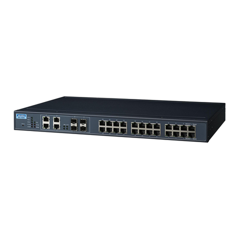
JetNet 5018G Series User manual

JetNet 3018G/4518/5012G/5018G Series
Industrial Gigabit Switch
Quick Installation Guide
www.korenix.com
V1.1

Introduction
The Quick Installation Guide is applied to the JetNet 5018G Series. The JetNet 5018G series
include JetNet 3018G, 16+2G Gigabit Switch; JetNet 5012G, 8+4G Industrial Managed
Switch; JetNet 5018G, 16+2G Industrial Managed Switch and JetNet 4518, 18-port Managed
Fast Ethernet Switch.
Additional model names, latest introductions and product datasheets can be found in Korenix
Web and Catalogue. The JetNet 5018G Series is designed as rugged surface in aluminum
material and with wide operating temperature. The managed switches’ software supports full
L2 management features, ring redundancy, network control, security and alert features. The
managed switches also support RS-232 console for out of band management.
Hardware Installation
1. Unpack the box, you will find
4JetNet Industrial Switch
4Quick Installation Guide
4CD User Manual
4Wall Mount plate and Mounting kit
4Ethernet port protective caps
4RS-232 Console Cable (Managed Switch only)
2. Mounting the unit
You can mount the din-rail clip on the rear of JetNet
switch on the DIN rail.
10/100 Base-TX
16
18
8
16
10/100/1000 Base-T
2 (Combo with SFP)
2 (Combo with SFP)
2 (Combo with SFP)
100 Base-FX
2 (Combo with Port 17,18)
1000 Base-X SFP
2
4 (2 Combo + 2 SFP)
2
Model Name
JetNet 3018G
JetNet 4518
JetNet 5012G
JetNet 5018G

3. Power the unit and connect to network
3.1 Connect the PWR1 / PWR2, and the unit will power on. PWR1 / PWR2 LED will turn
Red to show the unit is booting up. When the unit is ready, the LED turns Green.
Device Management
JetNet Industrial Managed Switch provides both in-band and out-band configuration
methods. You can configure the switch via the RS232 console with the attached console
cable or you can remotely manage the switch via network. You can choose Telnet/SSH, Web/
HTTPS management.
3.2 Connect the 10/100M Ethernet Port: Connect the network nodes to the JetNet switch
with 2/4-pair CAT5 UTP cable. The 10/100M interfaces support auto MDI/MDIX.
3.3 Connect the Gigabit TX of combo ports: Connect the network node to the JetNet switch
with 4-pair CAT5 UTP cable. The Gigabit TX interfaces support auto MDI/MDIX as well.
3.4 Connect the SFP transceiver: Plug in SFP fiber transceiver. We recommend using
Korenix certificated SFP mini GBIC transceiver. Cross-connect the transmit channel at
each end to the receive channel at the opposite end as illustrated in the figure below.
V+ V- V+ V-
Power1 Power2 Accept 12~24AWG wire. The switch
provides polarity reverse protection
Ȋ
This is a Class 1 Laser/LED product.
Don’t stare at the Laser/LED Beam.
TX
RX
AB
TX
RX
ATTENTION
3.5 If you need to connect the Relay Output, please refer to the wiring method introduced
in the manual.
1. Preparation for the console management: Attach the RS-232 DB9 connector to your PC’s
COM port. Connect the RJ-45 connector to the console port of the JetNet Industrial Managed
Switch.
1.1 Go to Start -> Program -> Accessories -> Communication -> Hyper Terminal

2. Preparation for Web management: Before you attempt to use the embedded web interface
for managing the switch operation, verify that your JetNet Managed Switch is properly
installed on your network and that every PC on this network can access the switch via the
web browser.
3. If you need to manage the switch by Telnet/SSH, please refer to the
JetNet 4518/5012G/5018G Manual.
Korenix Customer Service
KoreCARE is Korenix Technology’s global service center, where our professional staffs are
ready to answer your questions at any time.
1.2 Give a name to the new console connection.
1.3 Choose the COM name, and select the correct serial settings. The serial settings of
Managed Switches are as below:
Baud Rate: 9600 / Parity: None / Data Bit: 8 / Stop Bit: 1
1.4 After connected, Switch login is requested. Type the username and password to login.
The default username is “admin”, password is “admin”.
1.5 Follow the manual to configure the software features.
2.1 Launch the web browser (Internet Explorer or Mozilla
Firefox) on the PC.
2.2 Type http://Device’s IP_Address (The default IP address
is 192.168.10.1.) then press Enter.
2.3 The login screen will appear next. Type in the
username and the password. The default username
and password is admin/admin.
2.4 Click OK, and then the welcome page of the
web-based management interface will appear.
2.5 At the left column of the web management interface
are the software features, ring column will list the available settings.

ὖ䗄
ℸᖿ䗳ᅝ㺙ᇐ䗖⫼ѢJetNet 5018G㋏߫DŽJetNet 5018GࣙᣀJetNet 3018Gˈ16+2Gܚ
ᎹϮҹ㔥Ѹᤶᴎ˗JetNet 5012Gˈ8+4Gܚ㔥ㅵൟᎹϮҹ㔥Ѹᤶᴎ˗JetNet 5018Gˈ
16+2Gܚ㔥ㅵൟᎹϮҹ㔥ѸᤶᴎJetNet 4518, 18ষ㔥ㅵൟᎹϮҹ㔥ѸᤶᴎDŽ
ᙼৃҹKorenix㔥キঞѻકൟᔩϞᶹⳟᅠᭈⱘѻકৡ⿄ǃ᳔ᮄㅔҟঞѻકdatasheetDŽJetNet
5018G㋏߫䞛⫼മⱘ䪱ড়䞥䆒䅵ˈᬃᣕᆑ⏽Ꮉ⦃๗DŽ㔥ㅵൟѸᤶᴎ㋏߫ᬃᣕܼ䚼L2
㔥ㅵࡳ㛑ˈࣙᣀ⦃㔥ݫԭˈ㔥㒰ࠊˈᅝܼঞ䄺ࡳ㛑ㄝDŽ㔥ㅵൟѸᤶᴎ䖬ᦤկRS-232ࠊ
ッষ⫼Ѣᏺㅵ⧚DŽ
⹀ӊᅝ㺙
1. ᠧᓔࣙ㺙ˈẔᶹ䜡ӊ
4JetNetᎹϮҹ㔥Ѹᤶᴎ
4ᖿ䗳ᅝ㺙ᇐ
4⫼᠋ݠܝⲬ
4ຕᣖᠬᵓঞᅝ㺙䜡ӊ
4ҹ㔥ষ䰆ᡸา
4RS-232ࠊ㒓㓚(ҙ䰤㔥ㅵൟѸᤶᴎ)
2. 䆒ᅝ㺙
⫼JetNetѸᤶᴎ㚠ৢⱘᇐ䔼།ᇚ䆒Ϟᇐ䔼DŽ
10/100 Base-TX
16
18
8
16
10/100/1000 Base-T
2 (Combo with SFP)
2 (Combo with SFP)
2 (Combo with SFP)
100 Base-FX
2 (Combo with Port 17,18)
1000 Base-X SFP
2
4 (2 Combo + 2 SFP)
2
ᴎൟ
JetNet 3018G
JetNet 4518
JetNet 5012G
JetNet 5018G
CH

3. Ў䆒կ⬉ˈ䖲㔥㒰㒓
3.1 ᇚ⬉⑤䖲ࠄѸᤶᴎPWR1 / PWR2⬉⑤䕧ܹষˈ䆒䗮⬉ࡼDŽᔧPWR1 / PWR2
LEDᣛ⼎♃Ў㑶㡆ᯊ㸼⼎䆒ℷࡼˈᔧ䆒ℷᐌࡼৢˈLEDᣛ⼎♃Ӯব៤㓓㡆DŽ
䆒ㅵ⧚
JetNet㔥ㅵൟᎹϮҹ㔥Ѹᤶᴎᬃᣕᏺݙ(in-band)ঞᏺ(out-band)䆒㕂ᓣDŽ⫼᠋ৃҹ䗮䖛
RS232ࠊッষᇍѸᤶᴎ䖯㸠䆒㕂ˈ䗮䖛㔥㒰䖯㸠䖰ㅵ⧚DŽᙼৃҹ䗝ᢽTelnet/SSH, Web/
HTTPS⾡ㅵ⧚⬠䴶DŽ
1. Consoleㅵ⧚ⱘޚᎹ: ᇚRS-232 DB9༈䖲ࠄԴ䅵ㅫᴎⱘCOMষˈᇚRJ-45ッᦦܹ
JetNet㔥ㅵൟᎹϮҹ㔥ѸᤶᴎⱘconsoleッষDŽ
3.2 䖲10/100 TX⬉ষ: ⫼2/4-pair CAT5 UTPঠ㒲㒓ᇚ㔥㒰㡖⚍ܹѸᤶᴎˈ10/100Mッ
ষ㞾䗖ᑨMDI/MDIXDŽ
3.3 䖲ܚTX⬉ষ: ⫼4-pair CAT5 UTPঠ㒲㒓ᇚ㔥㒰㡖⚍ܹJetNet 5628GˈܚTX
⬉ষ㞾䗖ᑨMDI/MDIXDŽ
3.4 䖲SFPܝষ: ᦦܹSFPܝ㑸ᬊথ఼ഫDŽ㤤Փ⫼㒣Korenix⌟䆩䅸䆕ⱘSFP mini GBIC
ܝ㑸ᬊথ఼ഫDŽབϟ᠔⼎ˈᇚথ䗕ッ䖲ࠄⳂⱘ䆒ⱘᬊッˈ䖯㸠ѸঝѦ䖲DŽ
V+ V- V+ V-
Power1 Power2 ᬃᣕ12~24AWG ⬉⑤ˈѸᤶᴎᬃᣕℷ䋳ᵕ
ডֱᡸ
Ȋ
ℸЎClass 1 Laser/LEDܝষѻકˈ
ߛ࣓Ⳉ㾚▔ܝᴳDŽ
TX
RX
AB
TX
RX
⊼ᛣ
3.5 བᵰᙼ䳔㽕䖲㒻⬉఼䄺ˈ䇋খ㗗⫼᠋ݠЁⱘ䜡㒓䇈ᯢDŽ
1.1 䖤㸠Start -> Program -> Accessories -> Communication -> Hyper Terminal
1.2 Ўᮄ䖲ৡ
1.3 䗝ᢽCOMッষোˈ䆒ᅮℷ⹂ⱘІষখ᭄DŽ㔥ㅵൟѸᤶᴎⱘІষখ᭄བϟ:
⊶⡍⥛: 9600 / 偠ԡ: None / ᭄ԡ: 8 / ذℶԡ: 1

2. Webㅵ⧚ⱘޚᎹ: Փ⫼ጠܹᓣWeb⬠䴶ᇍѸᤶᴎᅲᮑㅵ⧚Пࠡˈ䇋ܜ偠䆕㔥ㅵൟѸᤶ
ᴎᏆ㒣ℷ⹂ܹ㔥㒰ˈϨ㔥㒰Ёⱘӏᛣ䅵ㅫᴎ䛑ৃҹ䗮䖛Web⌣㾜఼䆓䯂ѸᤶᴎDŽ
⾥⋯⧚ᗱଂৢ᳡ࡵ
KoreCARE ᰃ⾥⋯⧚ᗱ⾥ᡔܼ⧗᳡ࡵЁᖗˈ៥ӀϧϮⱘᡔᴃҎ䱣ᯊޚ㾷ㄨᙼⱘ⭥䯂DŽ
⾥⋯⧚ᗱܼ⧗᳡ࡵЁᖗE-mail˖[email protected]
1.4 ߎ⦄Ѹᤶᴎⱘⱏᔩ⬠䴶ˈ䬂ܹ⫼᠋ৡঞᆚⷕৃⱏᔩDŽ咬䅸⫼᠋ৡᰃĀadmināˈᆚⷕ
ᰃĀadminā
1.5 ձ⫼᠋᪡ݠ䖯㸠䕃ӊ䆒㕂
2.1 ᓔ䅵ㅫᴎϞⱘ⌣㾜఼ (IE⌣㾜఼Mozila Firefox)
2.2 ഄഔ䬂ܹhttp://䆒ⱘIPഄഔ
(咬䅸ⱘIPഄഔᰃ192.168.10.1.) ✊ৢEnter.
2.3 ߎ⦄ⱏᔩにষˈ䬂ܹ⫼᠋ৡᆚⷕⱏᔩѸᤶᴎDŽ
咬䅸ⱘ⫼᠋ৡᆚⷕᰃadmin/admin.
2.4 ⚍ߏOK, ߭Ӯߎ⦄webㅵ⧚⬠䴶ⱘЏ义.
2.5 义䴶ⱘᎺջᰃѸᤶᴎ乍ࡳ㛑ᇍᑨⱘҸDŽ
েջ߭Ӯᰒ⼎ᔧࠡ䆒ᅮDŽ
3.བᵰ䳔㽕Փ⫼Telnet/SSHㅵ⧚䅵ㅫᴎˈ
䇋খ㗗JetNet 4518/5012G/5018G⫼᠋ݠDŽ

Einführung
Dieser Quick Installation Guide gilt für die JetNet 5018G Serie. Die JetNet 5018G Series
enthält den JetNet 3018G, 16+2G Gigabit Switch; JetNet 5012G, 8+4G industrieller
administrierbarer Switch; JetNet 5018G, 16+2G industrieller administrierbarer Switch und
JetNet 4518, 18-port industrieller administrierbarer Switch.
Für weitere Modelle, neueste Entwicklungen und Produkt-Datenblätter siehe Korenix Web
und Katalog. Die JetNet 5018G Serie ist mit einer robusten Aluminium-Oberfläche und
einem weiten Betriebstemperatur-Bereich ausgestattet. Die Software der administrierbaren
Switche unterstützt volle L2 Managment-Funktionen, Ring Redundanz, Netzwerk Kontrolle,
Sicherheits- und Alarmfunktionen. Die administrierbaren Switche unterstützen auch eine
RS-232 Konsole für Out-of-band Managment.
Hardware Installation
1. im Lieferumfang enthalten sind
4JetNet Industrieller Switch
4Quick Installation Guide
4CD User Manual
4Wandbefestigungsplatte und Montage Kit
4Ethernet Port Schutzkappen
4RS-232 Konsol Kabel (nur administrierbare Switches)
2. Montage
Den Din-Schienen Clip an der Rückseite des JetNet
Switch an der DIN Schiene befestigen.
DE
10/100 Base-TX
16
18
8
16
10/100/1000 Base-T
2 (Combo with SFP)
2 (Combo with SFP)
2 (Combo with SFP)
100 Base-FX
2 (Combo with Port 17,18)
1000 Base-X SFP
2
4 (2 Combo + 2 SFP)
2
Model Name
JetNet 3018G
JetNet 4518
JetNet 5012G
JetNet 5018G

3. Anschalten des Geräts und Verbindung mit dem Netzwerk
3.1 Anschluss von PWR1 / PWR schaltet das Gerät ein. Die roten PWR1 / PWR2 LED
zeigen den Bootvorgang an. Wenn das Gerät bereit ist, wird die LED grün.
Administration des Geräts
JetNet industrielle administrierbare Switche verfügen über beides, in-band und out-band
Konfiguration. Das Gerät kann bei angeschlossenem Konsol-Kabel über die RS-232 Konsole
administriert werden oder remote über das Netzwerk per Telnet/SSH oder Web/HTTPS
Managment.
3.2 Den 10/100M Ethernet Port verbinden: Die Netzwerkgeräte über 2/4-paariges CAT5
UTP Kabel mit dem JetNet Switch verbinden. Das 10/100M Interface unterstützt auto
MDI/MDIX.
3.3 Den Gigabit TX Combo Port verbinden: Die Netzwerkgeräte über 2/4-paariges CAT5
UTP Kabel mit dem JetNet Switch verbinden. Der Combo Port unterstützt ebenfalls auto
MDI/MDIX.
3.4 Den SFP Transceiver verbinden: Den SFP Glasfaser Transceiver einstecken. Wir
empfehlen Korenix zertifizierte SFP mini GBIC Transceiver. Den Transmit Kanal am
anderen Ende mit dem Receive Kanal kreuzweise verbinden und umgekehrt wie in der
Abbildung zu sehen.
V+ V- V+ V-
Power1 Power2 Für 12~24AWG Draht. Der Switch verfügt
über Verpolungsschutz
Ȋ
Class 1 Laser/LED Produkt !
Nicht in den Laser/LED Strahl blicken!
TX
RX
AB
TX
RX
ATTENTION
3.5 Für den Anschluss des Relais Ausgangs ist die Verdrahtung im Handbuch beschrieben.
1. Vorbereitung für die Konsol-Administration: Den RS-232 DB9 Stecker am PC COM Port
anstecken. Den RJ-45 Stecker am Konsol-Port des industriellen administrierbaren JetNet
Switch anstecken.

2.Vorbereitung für Web Managment: Vor Benutzung der eingebauten Web-Schnittstelle
zur Administration des Switches die Verbindung des Switches im Netzwerk und die
Erreichbarkeit des Switches via Web-Browser von den im Netzwerk befindlichen PCs prüfen.
Den Webbrowser (Internet Explorer or Mozilla Firefox) am PC starten.
3. Für die Administratioin per Telnet/SSH, bitte im
JetNet 4518/5012G/5018G Handbuch nachschlagen.
Korenix Kunden Service
KoreCARE ist Korenix Technology’s globales Service Center, wo unsere professionellen
Mitarbeiter zu jeder Zeit bereit sind Ihre Probleme zu lösen
1.1 Auswählen: Start -> Program -> Accessories -> Communication -> Hyper Terminal
1.2 Einen Namen für die Hyperterminal-Sitzung vergeben
1.3 Den richtigen COM Port und die seriellen Parameter auswählen. Die seriellen
Parameter der administrierbaren Switche sind die folgenden:
Baud Rate: 9600 / Parity: None / Data Bit: 8 / Stop Bit: 1
1.4 Wenn verbunden, wird der Switch login abgefragt. Für das Login den Username und
das Passwort eingeben. Der Standard Username ist “admin”, das Passwort ist “admin”.
1.5 Die Software-Funktionen dem Handbuch entnehmen.
2.1 Eingabe: http://Device’s IP_Address
(The default IP address is 192.168.10.1.) und dann Enter.
2.2 Der Login Bildschirm erscheint. Username und Passwort
eingeben. Standard Username und Passwort ist admin/admin.
2.3 OK klicken, und die Welcome Seite der web-basierten
Oberfläche erscheint
2.4 In der linken Spalte der Oberfläche sind die Software-
Funktionen, rechts die verfügbaren Einstellungen.

Introduction
Ce guide d’installation rapide s’aplique à la série JetNet 5018G. La série JetNet 5018G
inclue les JetNet 3018G; JetNet 4518, JetNet 5012G, et JetNet 5018G.
Les guides d’installation pour d’autres modèles, les nouveaux produits et les documentations
commerciales peuvent être trouvés sur le catalogue ou le site web Korenix. La série JetNet
5018G est fabriqué en aluminium robuste, et fonctionne en gamme de température étendue..
Le logiciel supporte les fonctions completes de management L2, la redondance en anneau,
le contrôle du réseau et les fonctions de sécurités et d’alarmes. Les switches manageable
supportent également une console RS-232 pour le management en local.
Installation Matérielle
1.Déballage du matériel
En ouvrant la boite, vous trouverez :
4Le Switch Industriel JetNet
4Ce guide d’installation rapide
4Le manuel utilisateur sur CD
4La platine de montage murale et le nécéssaire
de fixation
4Des bouchons de protection des ports Ethernet
4Le câble de console RS-232 (Switch Manageable
seulement)
2. Installation du matériel
Vous pouvez installer le clip pour rail-Din à l’arrière du boitier.
3.Alimentation du matériel et raccordement au réseau
3.1 Connecter PWR1 / PWR2, et le materiel sera alimenté. les LED’s PWR1 / PWR2
LED s’allumeront en rouge pour indiquer que le switch démarre. Lorsque le switch est
prêt, les LED’s passeront au vert. FR
10/100 Base-TX
16
18
8
16
10/100/1000 Base-T
2 (Combo with SFP)
2 (Combo with SFP)
2 (Combo with SFP)
100 Base-FX
2 (Combo with Port 17,18)
1000 Base-X SFP
2
4 (2 Combo + 2 SFP)
2
Model Name
JetNet 3018G
JetNet 4518
JetNet 5012G
JetNet 5018G

3.2 Connecter les ports ETHERNET 10/100M: Connectez le réseau au Switch JetNet en
utilisant du câble UTP CAT5 2/4 paires..Les interfaces supportent automatiquement MDI/
MDIX.
3.3 Connecter le port Gigabiit TX des ports combo : Connectez le réseau au switch JetNet
en utilisant du câble UTP CAT 5 4 paires. Les interfaces supportent automatiquement MDI/
MDIX également.
3.4 Connecter le transceiver SFP: Insérez le transceiver fibre SFP.Nous recommandons
d’utiliser un transceiver SFP Mini GBIC certifié par Korenix Connectez les canaux
d’émissions et de réception en croisant les canaux tels que décrit sur l’illustration
ci-dessous.
V+ V- V+ V-
Power1 Power2 Accepte du câble de jauges 12~24AWG . Les entrées
sont protégées contre les inversion de polarités.
Ȋ
This is a Class 1 Laser/LED product.
Don’t stare at the Laser/LED Beam.
TX
RX
AB
TX
RX
ATTENTION
3.5 Si vous devez connecter la sortie relais, merci de vous réferrez à la method de câblage
décrite dans le manuel.
Gestion Lgicielle
Les switchs industriels manageable JetNet propose deux methods de configuration, distante
ou locale. Vous pouvez configurer le Switch via le port RS-232 en utilisant le câble fourni, ou
vous pouvez le configurer à distance via le réseau. Vous pouvez utiliser Telnet/SSH, Web/
HTTPS pour le configurer.
1. Preparation pour la configuration en local: Brancher le connecteur DB9 RS-232 DB9 sur
votre PC. Connecter le connecteur RJ-45 au port console JetNet.
1.1 Démarrez -> Programme -> Accessoires -> Communication -> Hyper Terminal
1.2 Donnez un nom à la connexion.

2. Préparation pour la configuration distante:Avant d’essayer d’utiliser l’interface enfoui
pour configure le switch, assurez vous que le Switch JetNet est correctement installé sur le
réseau, et que chaque PC du réseau peut y accéder à l’aide d’un explorateur internet.
3. Si vous devez configurer le switch par Telnet/SSH, referrez vous au manuel utilisateur.
Service Client Korenix
KoreCARE est le service client de Korenix, ou nos specialists sont prêts à répondre à vos
questions à tout moment.
1.3 Choisissez le port COM ,et sélectionnez les paramètres du port série :
Baud Rate: 9600 / Parity: None / Data Bit: 8 / Stop Bit: 1
1.4 Après la connexion, un mot de passe est requis. Taper le nom d’utilisateur et le mot de
passe pour se connecter.Le nom d’utilisateur par défaut est “admin”, et le mot de passe est
“admin”.
1.5 Suivre le manuel utilisateur pour la configuration logicielle.
2.1 Lancer l’explorateur internet surle PC
2.2 Taper http://Adress IP du switch (l’addresse IP par
défaut est 192.168.10.1.) et presser Entrée.
2.3 L’écran de connexion va apparaitre. Taper le nom
d’utilisateur et le mot de passe pour se connecter.Le nom
d’utilisateur par défaut est “admin”, et le mot de passe
est “admin”.Click OK, and then the welcome page of
the web-based management interface will appear.
2.4 La colonne de gauche affiche les options du logiciel,
la colonne de droite affichera les options disponibles.

Introducción
La Guía Rápida de Instalación es aplicable para las Series JetNet 5018G. Estas series
incluyen al JetNet 3018G, Switch Gigabit 16+2G, al JetNet5012G, Switch Industrial
Gestionable 8+4G y al JetNet 5018G, Switch Industrial Gestionable 16+2G et JetNet 4518,
Switch Industrial Gestionable 18-port.
Nombres adicionales de modelos, últimas incorporaciones y datasheets de producto pueden
ser localizados en la Web de Korenix y en los Catálogos. La Serie JetNet 5018G tiene un
diseño que comprende una robusta superficie de Aluminio y un amplio rango de temperatura
de trabajo. El software del switch soporta unas características de gestión L2 completas,
redundancia en anillo, control de red, propiedades de alerta y seguridad, etc. Los switches
gestionables también soportan consola RS-232 para gestión fuera de banda.
Instalación de Hardware
1. Desempaquetando la caja, Ud. encontrará
4El propio Switch Industrial JetNet
4Guía Rápida de Instalación
4CD con el Manual de Usuario
4Pletina para montaje en pared y kit de montaje
4Capuchones protectores de los puertos Ethernet
4Cable Consola RS-232 (Sólo para Switches
gestionables)
2. Instalando la unidad
Ud. Puede usar el clip raíl-Din de la parte trasera del
switch para insertarlo en el raíl DIN.
SP
10/100 Base-TX
16
18
8
16
10/100/1000 Base-T
2 (Combo with SFP)
2 (Combo with SFP)
2 (Combo with SFP)
100 Base-FX
2 (Combo with Port 17,18)
1000 Base-X SFP
2
4 (2 Combo + 2 SFP)
2
Model Name
JetNet 3018G
JetNet 4518
JetNet 5012G
JetNet 5018G

3. Alimentación de la unidad y conexión a la red
3.1 Conecte PWR1 / PWR2 y la unidad se encenderá. El led PWR1 / PWR2 LED lucirá de
color Rojo para mostrar que la unidad está arrancando. Cuando la unidad esté lista, el led
cambiará a color Verde.
Gestión del Dispositivo
El Switch Industrial Gestionable proporciona ambos métodos de configuración, en banda y
fuera de banda. Ud. puede configurar el switch a través de la consola RS232 mediante el
cable adjunto, o también puede gestionarlo de manera remota a través de la red. Se pueden
seleccionar tanto gestión Telnet/SSH como Web/HTTPS.
1. Preparación para gestión por consola: Conecte el DB9 RS-232 del cable al puerto COM
del ordenador. Conecte el conector RJ-45 del otro extremo de dicho cable al puerto de
consola del Switch JetNet Industrial Gestionable.
3.2 Conecte los Puertos Ethernet 10/100M: Conecte los nodos de red al switch JetNet
mediante cable 2/4-pares CAT5 UTP. Los interfaces 10/100M soportan auto MDI/MDIX.
3.3 Conecte los Puertos Gigabit TX o Combo: Conecte los nodos de red al switch JetNet
mediante cable 4-pares CAT5 UTP. Los interfaces Gigabit TX soportan así mismo auto
MDI/MDIX.
3.4 Conecte los transceptores SFP: Inserte los transceptores de fibra SFP. Se recomienda
usar transceptores Korenix certificados SFP mini GBIC. Interconecte el canal de
transmisión de un lado con el de recepción del lado opuesto y viceversa, tal como se
ilustra en la siguiente figura.
V+ V- V+ V-
Power1 Power2 Acepta conexión 12~24AWG. El switch está protegido
ante una posible conexión de polaridad invertida.
Ȋ
Este es un equipo Laser/LED clase 1.
No encarar la vista al rayo Laser/LED.
TX
RX
AB
TX
RX
ATENCION
3.5 Si se necesitara conectar el Relé de Salida, por favor remítase al modo de cableado
que se explica en el manual.

2. Preparación para gestión vía Web: Antes de intentar utilizar el interface web embarcado
para gestionar el funcionamiento del switch, verifique que su Switch JetNet Gestionable esté
correctamente instalado en su red y que todos los ordenadores de esa red puedan acceder
al switch mediante dicho navegador web.
3. Si se necesitara gestionar el switch mediante Telnet/SSH, por favor remítase al manual
del JetNet 4518/5012G/5018G.
Servicio Korenix a clientes
KoreCARE es el centro desde donde se ofrece el servicio global de soporte sobre Tecnología
Korenix, desde donde nuestros profesionales están preparados para resolver sus problemas
en todo momento.
1.1 Vaya a Start -> Program -> Accessories -> Communication -> Hyper Terminal
1.2 Déle un nombre a la nueva conexión de consola.
1.3 Elija el nombre del COM, y seleccione unos parámetros serie adecuados. Los
parámetros serie en Switches gestionables son: Rango de baudios: 9600 / Paridad: No /
Bit de datos: 8 / Bit de parada: 1
1.4 Después de conectar, el Switch pedirá un login. Escriba un nombre de Usuario y
Contraseña para entrar. Por defecto éstos son “admin” / “admin”.
1.5 Siga el manual para configurar las características de software.
2.1 Lance el navegador web (Internet Explorer o Mozilla
Firefox) en el PC.
2.2 Escriba http://Dirección IP del dispositivo(La dirección
IP es 192.168.10.1) luego presione Enter.
2.3 La ventana de acceso aparecerá seguidamente.
Escriba el nombre de usuario y contraseña, que por
defecto son admin/admin.
2.4 Pulse OK, y la página de bienvenida del interface
web aparecerá a continuación. En la columna de la
izquierda del interface web están las características de
software, donde se listan los posibles ajustes.

Введение
Руководство по быстрому старту применяется для коммутаторов серии JetNet 5018G.
Эта серия включает в себя JetNet 3018G, 16+2G Gigabit коммутатор; JetNet 5012G,
8+4G промышленный управляемый коммутатор; JetNet 5018G, 16+2G промышленный
управляемый коммутатор и JetNet 4518, 18-port промышленный управляемый
коммутатор.
Дополнительные названия моделей, последние новинки и справочные материалы
доступны на сайте и в каталоге компании Korenix. Продукты серии JetNet 5018G имеют
прочную поверхность из алюминия и могут работать в широком диапазоне температур.
Программное обеспечение управляемых коммутаторов поддерживает полный набор
функций L2 управления, резервирование по типу «кольцо», управление сетью, функции
системы безопасности и системы предупреждения. Управляемые коммутаторы имеют
также консоль RS-232 для конфигурирования устройства.
Установка аппаратной части
1. Открыв коробку, Вы обнаружите:
4Промышленный коммутатор JetNet
4Руководство по быстрой установке (QIG)
4Руководство пользователя на CD
4Плата и набор деталей для монтажа
4Заглушки для порта Ethernet
4Кабель для консоли RS-232 (только для
управляемого коммутатора)
2. Монтаж платы
Вы можете установить коммутатор, закрепив его с помощью
зажима на задней стенке устройства к DIN рейке.
RU
Название мод
JetNet 3018G
JetNet 4518
JetNet 5012G
JetNet 5018G
16
18
8
16
2
2
10/100 Base-TX 10/100/1000 Base-T
2 (комбинированные
с SFP)
2 (комбинированные
с SFP)
2 (комбинированные
с SFP)
2 (комбинированные
с SFP)
100 Base-TX 1000 Base-X SFP
4 (2 комбинированные
+ 2 SFP)
2 (комбинированные
с Port 17,18)

3. Включение питания платы и подсоединение к сети
3.1 Подключите PWR1 / PWR2, и плата будет запитана. Светодиод PWR1 / PWR2
загорится красным цветом, что обозначает процесс загрузки. Когда плата будет готова
и загрузка завершится, светодиод станет зеленым.
Управление устройством
Промышленный управляемый коммутатор JetNet обеспечивает локальный и удаленный
способы конфигурирования устройства. Вы можете настраивать коммутатор с
помощью консоли RS-232, подключив соответствующий кабель, или управлять работой
коммутатора удаленно по сети. Вы можете выбрать протоколы Telnet/SSH, Web/HTTPS.
1. Подготовка к локальному конфигурированию: Вставьте коннектор RS-232 DB9 в COM
порт Вашего компьютера. Вставьте коннектор RJ-45 в порт консоли промышленного
управляемого коммутатора JetNet.
3.2 Подключите 10/100M Ethernet порт: подсоедините сетевые узлы к коммутатору
JetNet с помощью 4/8-жильного CAT5 UTP кабеля. Интерфейс 10/100M поддерживает
функцию авто MDI/MDIX.
3.3 Подключите комбинированные порты Gigabit TX: подсоедините сетевой узел к
коммутатору JetNet с помощью 8-жильного CAT5 UTP кабеля. Интерфейс Gigabit TX
также поддерживает функцию авто MDI/MDIX.
3.4 Подключите SFP трансивер: включите в сеть оптоволоконный SFP трансивер.
Мы рекомендуем использовать SFP трансивер mini GBIC, сертифицированный
компанией Korenix. Соедините канал передачи на одном конце с каналом приема на
противоположном конце, как показано на рисунке ниже.
V+ V- V+ V-
Power1 Power2 Допустимый размер провода 12~24AWG. Коммутатор
обеспечивает защиту от подачи напряжение неправильной
полярности
Ȋ
Это продукт Класса 1 Лазер/Светодиод.
Не смотрите на лазерный/светодиодный
луч.
TX
RX
AB
TX
RX
ВНИМАНИЕ!
3.5 Если Вам необходимо подключить релейный выход, воспользуйтесь методом
подключения, представленном в руководстве пользователя.

2. Подготовка к удаленному (Web-) управлению: Перед тем, как воспользоваться
встроенным web-интерфейсом для управления коммутатором, проверьте, что Ваш
управляемый коммутатор JetNet правильно подключен к локальной сети и каждый
компьютер сети может получить доступ к коммутатору с помощью web-браузера.
3. Если Вы хотите использовать протокол Telnet/SSH для управления коммутатором,
пожалуйста, обратитесь к руководству пользователя для устройств
JetNet 4518/5012G/5018G.
Сервисный центр Korenix
KoreCARE - глобальный сервисный центр Korenix Technology, где специалисты фирмы
готовы прийти на помощь в любое время и решить проблемы пользователей.
1.1 Зайдите в меню Пуск -> Программы -> Стандартные -> Связь -> Hyper Terminal
1.2 Дайте имя новому консольному подключению.
1.3 Выберите COM порт, и установите для него правильные параметры. Параметры
COM порта для управляемых коммутаторов должны быть следующими:
Скорость: 9600 / Четность: Нет / Биты данных: 8 / Стоповые биты: 1
1.4 После подключения требуется выполнить регистрацию. Введите имя пользователя
и пароль. По умолчанию имя пользователя: admin, пароль: admin.
1.5 Следуйте инструкциям руководства пользователя для работы с программным
обеспечением.
2.1 Запустите web-браузер (Internet Explorer или Mozilla
Firefox) на Вашем компьютере.
2.2 В строку адреса введите http:// IP_Адрес Устройства
(IP-адрес по умолчанию 192.168.10.1.), затем нажмите
Enter.
2.3 Появится диалог регистрации. Введите имя
пользователя и пароль. Имя пользователя и пароль
по умолчанию admin/admin.
2.4 Нажмите OK, затем появится страница
приветствия интерфейса web-ориентированного
управления.
2.5 Левая колонка интерфейса содержит список
функциональных возможностей, а правая – список
параметров для настройки соответствующего раздела.

Tel:+886-2-89111000
Fax:+886-2-29123328
Business service:[email protected]
Customer service:[email protected]
CPQ000N5018001
This manual suits for next models
4
Table of contents
Languages:
Other JetNet Switch manuals
