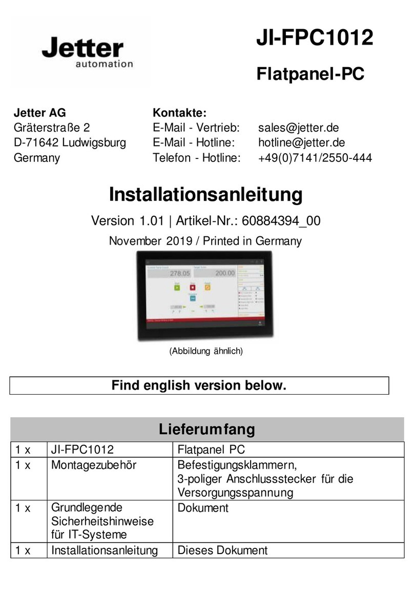
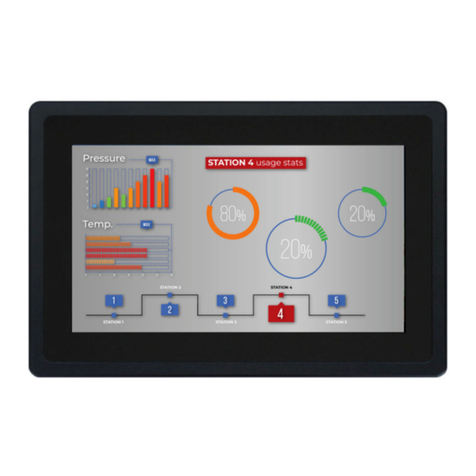
Jetter JI-FPC1015 User manual

JI-FPC1015
Flatpanel-PC
Jetter AG
Kontakte:
Gräterstraße 2
E-Mail - Vertrieb:
sales@jetter.de
D-71642 Ludwigsburg
E-Mail - Hotline:
hotline@jetter.de
Germany
Telefon - Hotline:
+49(0)7141/2550-444
Installationsanleitung
Version 1.00 | Artikel-Nr.: 60884758
November 2019 / Printed in Germany
(Abbildung ähnlich)
Find english version below.
Lieferumfang
1 x
JI-FPC1015
Flatpanel PC
1 x
Montagezubehör
Befestigungsklammern,
3-poliger Anschlussstecker für die
Versorgungsspannung
1 x
Grundlegende
Sicherheitshinweise
für IT-Systeme
Dokument
1 x
Installationsanleitung
Dieses Dokument

Maße
Jetter
JI-FPC1015

Montage Fronttafeleinbau
Um den frontseitigen Schutzgrad von IP65 zu gewährleisten, achten Sie
bitte auf den korrekten Zustand der Dichtung und eine glatte und saubere
Oberfläche.
Achten Sie auf genügend Freiraum zum Anschluss der Kabel
Lassen Sie mindestens 5cm Freiraum (rückseitig) um das Gerät herum,
damit eine entsprechende Luftzirkulation stattfinden kann.
Ausschnittmaß
398mm x 282mm
Empfohlene
Wandstärke für
korrekten Sitz
1,5mm –6mm
Halteklammern
8 St. =>
Werkzeug
Innensechskantschlüssel (INBUS®) 2mm
Anzugsmoment
0,7 Nm
Ausschnittsmaße für Fronttafeleinbau
Ausschnitt für
JI-FPC1015
398 mm
282 mm
Achten Sie auf die korrekte horizontale und vertikale Ausrichtung.

VESA 75/100 Montage
Der JI-FPC1015 kann auch in vertikaler Positionan einer VESA 75/100
Befestigungsvorrichtung montiert werden. Das Gerät kann gedreht werden
um die Bildschirmausrichtung im Quer- oder Hochformat zu ermöglichen.
Mindestabstände
Um eine ausreichende Luftzirkulation zu gewährleisten, müssen bei der
Montage des Geräts nach allen Seiten mindestens 5 cm Mindestabstand
eingehalten werden.

Anschlüsse
1.) (X1) Versorgung 24VDC
6.) (X8) SD-Card Steckplatz
2.) (X2,3) 2 x Ethernet
7.) (X9) Display Port
3.) (X4) 1 x USB 3.0
8.) EIN-/AUS-Schalter
4.) (X5,6) 2 x USB 2.0
9.) LED Aktivität
Massenspeicher
5.) (X7) 1 x COM1 (RS-232)
10.) LED Power
11.) Erdungsbolzen + Symbol
Anschlussbeschreibung X1 Spannungsversorgung
2 31
+ -
1.) Phoenix Stecker 3-polig
4.) Klemme Schirmanschluss
2.) Abdeckung Schrauben
5.) Klemme 0 V
3.) Klemme 10-30V DC
Anschlusswerte
Spannung
10 -30 V DC
Strom
3 A max.

Anschlussbeschreibung X7 COM1 (RS-232)
1 DCD (Data Carrier Detect)
2 RXD (Receive Data)
3 TXD (Transmit Data)
4 DTR (Data Terminal Ready)
5 GND (Signal Ground)
6 DSR (Data Set Ready)
7 RTS (Request to Send)
8 CTS (Clear to Send)
9 RI (Ring Indicator)
Anschlussbeschreibung X9 DisplayPort
1 ML Lane 0 (p)
2 GND (ML Lane 0)
3 ML Lane 0 (n)
4 Lane 1 (p)
5 GND (ML Lane 1)
6 Lane 1 (n)
7 Lane 2 (p)
8 GND (ML Lane 2)
9 Lane 2 (n)
10 Lane 3 (p)
11 GND (ML Lane 3)
12 Lane 3 (n)
13AUX SEL#
14 Pull-down to GND
15AUX CH (p)
16 GND (AUX CH)
17AUX CH (n)
18 Hot Plug
19 GND (GND_DDC)
20 3.3V
(DDC EEPROM
Versorgung 500 mA
max.)

Anschlussbeschreibung X5,6 USB2.0 Ports
1 VCC (900 mA max.)
2 Data-
3 Data+
4 GND (Versorgung)
Anschlussbeschreibung X4 USB3.0 Port
USB2.0
USB3.0
1 VCC (900 mA
max.)
5 StdA_SSRX-
2 Data-
6 StdA_SSRX+
3 Data+
7 GND_DRAIN
4 GND (Versorgung)
8 StdA_SSTX-
9 StdA_SSTX+
Anschlussbeschreibung X2,3 Ethernet (RJ-45)
linke LED rechte LED
1 MDI0+
2 MDI01
3 MDI1+
4 MDI2+
5 MDI2-
6 MDI1-
7 MDI3+
8 MDI3-
LED Statusanzeige
Linke LED
Rechte LED
AUS
Keine Verbindung
AUS
10 Mbit/s
Grün, dauernd
Verbindung OK
Grün, dauernd
100 Mbit/s
Grün, blinkend
Verbindung OK mit
Datenverkehr
Gelb, dauernd
1.000 Mbit/s


JI-FPC1015
Flatpanel PC
Jetter AG
Communications
Gräterstraße 2
E-Mail - Sales:
sales@jetter.de
D-71642 Ludwigsburg
E-Mail - Hotline:
hotline@jetter.de
Germany
Phone - Hotline:
+49(0)7141/2550-444
Installation Manual
Revision 1.00 | Item # 60884758
November 2019 / Printed in Germany
(Similar picture)
Scope of delivery
1 x
JI-FPC1015
Flatpanel PC
1 x
Mounting accessories
Mounting clamps,
DC power terminal
1 x
General safety
instructions for IT
equipment
Document
1 x
Installation Manual
This document

Physical dimensions
Jetter
JI-FPC1015

Wall mounting
In order to ensure IP65 front sealing against dust and water, mount the
system on a non-textured surface.
Keep clerance for cabling
Leave at least 5 cmof free space around the unit to prevent the device from
possibly overheating! Do not obstruct the air intake and exhaust openings..
Cut-out for mounting to a
wall/panel (W x H) [mm]
312mm x 250mm
Thickness of the mounting
wall/panel for proper
mounting [mm]
1,5mm –6mm
Clamp with screws for
mounting the FusionClient
to a wall/panel
8 x =>
Required tool
Allen Wrench 2mm
Proper Torque
0,7 Nm
Wall / panel cut out dimensions
Wall / panel cut out for
JI-FPC1015
398 mm
282 mm
In order to ensure IP65 front sealing against dust and water, mount the
system on a non-textured surface.
Ensure the vertical and horizontal alignment of the system/display unit.

VESA 75/100 mounting
The FusionClient can be mounted to a VESA 75/100 compliant mounting
system (in vertical position with the interfaces downwards). The
FusionClient mounted to a VESA 75/100 compliant mounting system may
be rotated to left or right in order to view landscape or portrait images if the
installed operating system supports this feature. Ensure that the length of
the cable connections to power and peripherals are sufficient for this
operating position..
Minimum spacing
Leave at least 5 cm(approx. 2") of free space aroundthe unit to prevent the
device from possibly overheating! Do not obstruct the air intake andexhaust
openings.
The voltage feeds must not be overloaded. Adjust the cabling and the
external overload protection to correspond with the rated voltage range
indicated on the type label.

Overview - Interfaces and connections
6.) (X1) Power supply
6.) (X8) SD-Card slot
7.) (X2,3) 2 x Ethernet
7.) (X9) Display port
8.) (X4) 1 x USB 3.0
8.) Power button
9.) (X5,6) 2 x USB 2.0
9.) LED storage activity
10.) (X7) 1 x COM1 (RS-232)
10.) LED Power
11.) Grounding stud and symbol
X1 Power supply
2 31
+ -
1.) 3-pin Phoenix plug terminal
4.) Shield terminal
2.) Cover pan head screws
5.) 0 V terminal
3.) 10-30V DC terminal
Electrical specifications
Power supply
10 -30 V DC
Power consumption
3 A max.

X7 COM1 (RS-232)
1 DCD (Data Carrier Detect)
2 RXD (Receive Data)
3 TXD (Transmit Data)
4 DTR (Data Terminal Ready)
5 GND (Signal Ground)
6 DSR (Data Set Ready)
7 RTS (Request to Send)
8 CTS (Clear to Send)
9 RI (Ring Indicator)
X9 Display port
1 ML Lane 0 (p)
2 GND (ML Lane 0)
3 ML Lane 0 (n)
4 Lane 1 (p)
5 GND (ML Lane 1)
6 Lane 1 (n)
7 Lane 2 (p)
8 GND (ML Lane 2)
9 Lane 2 (n)
10 Lane 3 (p)
11 GND (ML Lane 3)
12 Lane 3 (n)
13AUX SEL#
14 Pull-down to GND
15AUX CH (p)
16 GND (AUX CH)
17AUX CH (n)
18 Hot Plug
19 GND (GND_DDC)
20 3.3V (DDC EEPROM
power 500 mA fused)

X5 + X6 USB2.0 ports
1 VCC (900 mA max.)
2 Data-
3 Data+
4 GND (ground for power return)
X4 USB3.0 port
USB2.0
USB3.0
1 VCC (900 mA
max.)
5 StdA_SSRX-
2 Data-
6 StdA_SSRX+
3 Data+
7 GND_DRAIN
4 GND (ground for
power return)
8 StdA_SSTX-
9 StdA_SSTX+
X2 +X3 Ethernet (RJ-45)
1 MDI0+
2 MDI01
3 MDI1+
4 MDI2+
5 MDI2-
6 MDI1-
7 MDI3+
8 MDI3-
LED states
Left LED
Right LED
OFF
Link not active
OFF
10 Mbit/s
Green,
constant on
Link active
Green,
constant on
100 Mbit/s
Green,
flashing
Link active plus
activity
Green,
flashing
1.000 Mbit/s

Table of contents
Languages:
Other Jetter Touch Panel manuals
