Jetview JE710PTZ User manual

Jetview® Model JE710PTZ
7” Pan-Tilt-Zoom Dome Camera
(24VAC)
User Manual
Rev. 0
(Sept. 01-2004)

Introductions
Thank you for purchasing the surveillance product from Jetview®(http://www.jetviewcam.com).
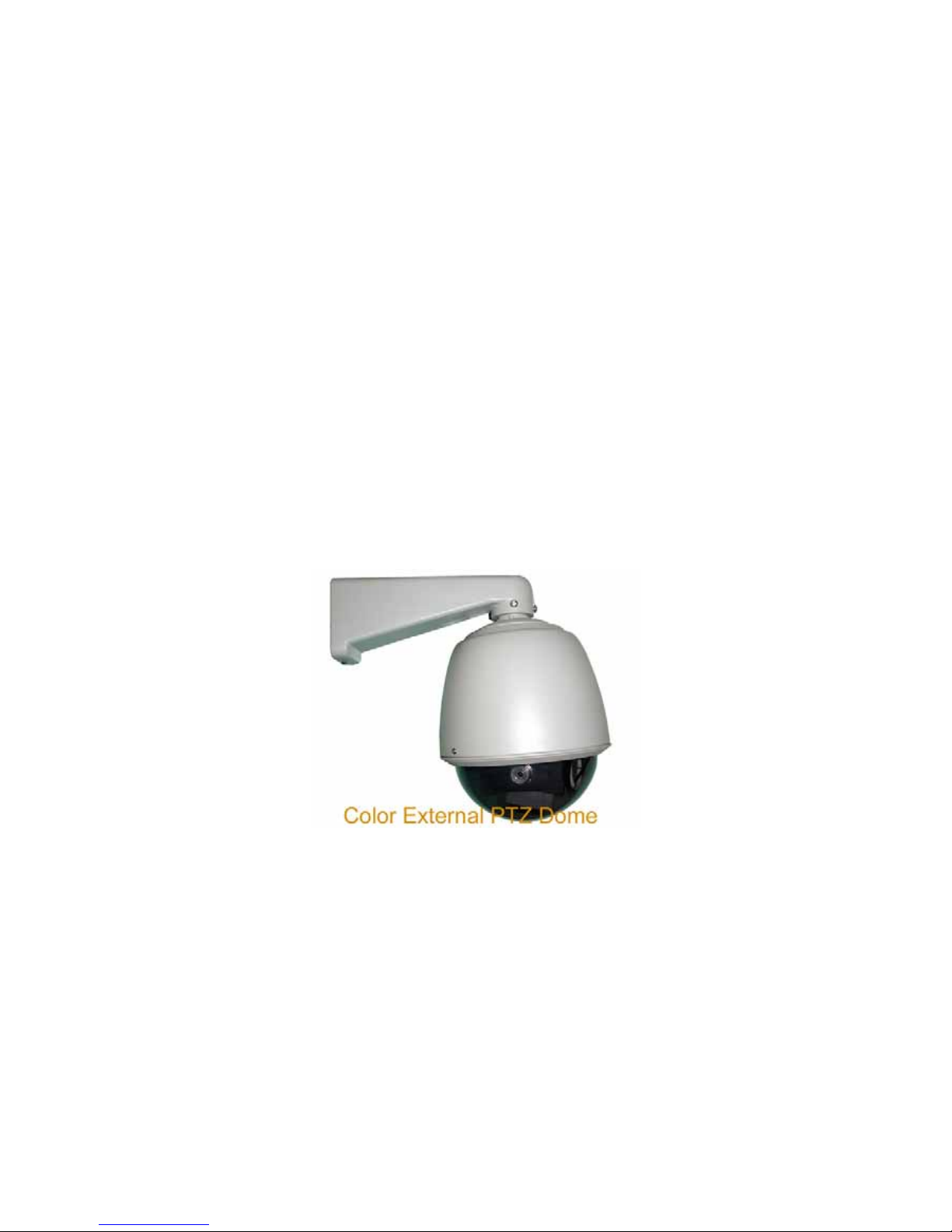
This is an all weather outdoor 7” dome PTZ (Pan-Tilt-Zoom) camera with the most powerful
features to meet your application requirement. Please read the following manual carefully before
use.
The PTZ camera has the following design features:
• Has a built-in controller for pan-tilt-zoom (PTZ), controlled by DVR system or keyboard
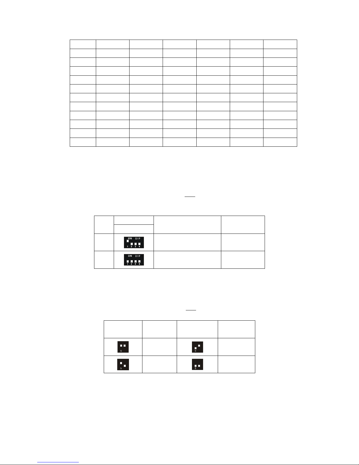
controller via RS485 (up to 1000m distance). Supports both Pelco-D and Pelco-P
protocols at 2400, 4800, 9600 baud rate. Camera address is selectable.
• Has total 128 preset positions. One programmable built-in auto cursing track (preset
position 1 to 10 selectable)
• Stylish design body and appearance. All weather outdoor capable.
• Dual layer body design for better hot weather and direct sunshine resistance
• Optional heater & fan system allowing unit to operate in low-temperature places
• Japan made PMMAmaterial dome cover for better image clarity
• Special precision bearing to guarantee smooth operation
• Famous VISTA precision motor for long life and reliable operation
• Weather and element resistant ABS material for main body
Attention:
• Do not use in temperature less than -10°C or +50°C;
• Do not expose the internal parts to rain or high humidity places
• Do not leave any foreign subjects to inside of the camera as it may cause electrical
shortage
• Do not let the camera subject to shock and shake;
• Do not touch the inside components when in use;
• Do not use the camera in places where air contains the toxic, combustion or acid gas
• Use soft cloth and warm water to clean dome cover;
• Use AC 24V only for this PTZ dome. Do not use AC 110V, 220V or DC 24V!! you can

damage the unit instantly.
1. The package contains the following items:
1 x metal arm
1 x dome cover
1 x main body including:
- 1 x 218X (or upgraded 220X) zoom camera
- 1 x PTZ controller (default setting Pelco-D, 2400 Baud, Camera ID:1)
3 x arm mounting screws
1 x cloth glove
2 x mounting screw for dome cover
1 x Instruction manual
2. Main structure (Fig. 1)
Fig. 1
3. Installation
3.1 Please read this manual carefully and contact the seller immediately if you have any questions
(e-mail: [email protected].cn ).
3.2 Install the camera chasse to the body, align the hole on the axle to the quick locking pin and
lift the arm to the lock position after put chasse fully into the position (Fig 2.).

Fig. 2
3.3 Install the arm to the main body by using three screws supplied. (Fig. 3).
Fig. 3
3.4 Dome cover installation
Use two mounting screws supplied, line up to two holes on the body and tighten up. Notice that
you may need a cloth glove to do this as scratches may occur if hard subject touching the dome
cover.
3.5. Cable connection
3.5.1 Connect the power cable labeled with “24V AC” to 24V AC power supply with minimum
1000mA. Warning:
Do not connect the unit to 24V DC or 110V AC or 220V AC as you will damage the unit
instantly!!

3.5.2 Connect the data cable labeled with “RS485 (+) and (-) to the RS485 output of your DVR
system or keyboard controller.
Note: The factory default setting for built-in controller is Pelco-D, 2400 Baud, Camera ID is “1”.
Please read the internal PTZ controller for other settings.
3.5.3 For unit with manual control, connect the cable labeled with “Up”, “Down”, “Left”, “Right”
and “Auto” to the corresponding input of the controller box (optional)
3.5.4 For unit with manual control, control the cable with “Zoom” and “Focus” to the
corresponding input of the controller box
3.6 Camera installation (Fig. 4)
(Pre-installed by the factory already)
Fig. 4
3.7 Rotation limit adjustment
The factory defaults for vertical are 0-90°and horizontal is 0-360°. If you need to make an
adjustment, please read the following instructions careful as you may damage the unit due to
improper adjustment.
Fig. 5
Use a hex key to loose the locking nut and then adjust the limit tab accordingly to the position

desired.
4. PTZ Dome Specifications
Specifications
Power input AC 24V, 50/60Hz
Power consumption 8 VA
Rotation angle Horizontal: 0-360° Vertical: 0-90° (adjustable)
Rotation Speed Horizontal 6.5°/sec; Vertical: 6.5°/sec
Temperature -10°C to 50°C (heater and fan (optional) can extend low temp limit)
Body: ABS
Bracket components: Aluminum alloy
Arm: Metal
Structure
Cover: PMMA
5.1 Camera Specifications
Camera:
TV System PAL/NTSC
1/4" SONY CCD 752(H) x 582 (V) (PAL) or 810(H) x 508 (V) (NTSC)
Image Sensor
625 TV Lines, 50 Fields/sec (PAL)
Scanning System 525 TV Lines, 60 Fields/sec (NTSC)
Sync System Internal/VD-Lock
Mini illumination 1Lux(F1.2) Typical 0.5Lux (F1.2)
Resolution 480TV Lines
S/N Ratio 48dB(Min.); 52dB(TYP) (AGC OFF; APC OFF)
White Balance ATW/AWB/FIX
White Balance Range 3200-9600ºK
B.L.C. Function Auto
Gamma Correction 0.45
AGC AUTO (18dB Max.)
ALC Auto/Fix
Electronic Shutter AES: 1/50 - 1/20000 Sec Manual 8 Steps
Lens 22X Optical Zoom Lens , F3.6-79.2mm
Zoom 22X Optical, 10X digital, total 220X
Focus Auto/Manual
Control PTZ controller or digital decorder
Video Output 1.0V p-p/75Ω(BNC Male)
Operation Temp. -10ºC - +50ºC
Power Supply DC 12V +/-10%
Dimensions 58mm X 61mm X 112mm
Weight 500g

6. Built-in PTZ controller
The built-in PTZ controller is also called “Decoder”. It converts the digital signals sent by the
DVR (Digital Video Recorder) into the analog ones for Pan, Tilt , Zoom and Focus control. The
built-in controller takes only RS 485 signal (+) and (-). The input voltage is AC 24V. Wrong power
input could cause server damage to the controller and the camera.
The controller has three settings that must match your DVR system before you are able to control
the unit. They are: camera ID, baud rate and protocol. Default factory settings are:
Camera ID: “1”
Protocol: PELCO-D
Baud rate: 2400
It is necessary to adjust above setting if your DVR system needs. To change the settings, please
read the instructions below carefully.
6.1. Camera ID setting
You can set the camera ID which matches your DVR system or keyboard controller by setting the
8-position dip switch SK1 (Switch 3 to 8, switch 1 and 2 for baud rate setting).
Camera
ID Switch
3 Switch
4 Switch
5 Switch
6 Switch
7 Switch
8
0 0 0 0 0 0 0
1 0 0 0 0 0 1
2 0 0 0 0 1 0
3 0 0 0 0 1 1
4 0 0 0 1 0 0
5 0 0 0 1 0 1
6 0 0 0 1 1 0
7 0 0 0 1 1 1

8 0 0 1 0 0 0
9 0 0 1 0 0 1
10 0 0 1 0 1 0
11 0 0 1 0 1 1
12 0 0 1 1 0 0
13 0 0 1 1 0 1
14 0 0 1 1 1 0
15 0 0 1 1 1 1
16 0 1 0 0 0 0
17 0 1 0 0 0 1
. . . . . . .
63 1 11 1 1 1 1
6.2 Protocol setting
Protocol setting is done via a 4-position dip-switch SK2.
Switch
Item
1 2 3 4 Protocol Baud Rate
1 Pelco-P 4800
2 Pelco-D 2400
6.3 Baud Rate setting
Baud rate setting is also done via Switch 1 and 2 of SK1.
Switch 1,2 Baud Switch 1,2 Baud
6
9600
6
2400
6
4800
6
1200
Note: dip-switch up is “on”
For example, if you need 2400 baud, Switch 1 is “off” and 2 is “on”.
It is very important that you must verify your com port baud rate setting, camera ID and protocol

of your DVR system to ensure 100% matching the PTZ camera setting.
Electronics for assistance.
Other Jetview Security Camera manuals